This value of electric current is used to power most household appliances in the house. Often, they receive their charge from battery-powered devices.
But if they break, then a problem arises: how to get 12 Volts AC?
This is what we will try to analyze further, recalling the most common options.
Get a voltage of 12 Volts from 220
This is a fairly common change that can be made in several ways:
- Reduce tension without using a distributor.
- Use a 50 Hz distributor.
- Connect a pulse transformer that can be combined with a straight-line rectifier.
HOW TO GET A REDUCTION WITHOUT USING A DISTRIBUTOR
This is only possible in three ways:
- Get a reduction using a damping element. Quite a popular method, used to recharge low-power devices. The disadvantages include a low power factor. However, it is often used in inexpensive devices.
- Limit the flow with a resistor. The option is not the best, but it is still used and is suitable for charging diodes. The main disadvantage is the large heat generation on the resistor.
- Use an automatic distribution transformer or a similarly wound coil.
How to get 12V from improvised means
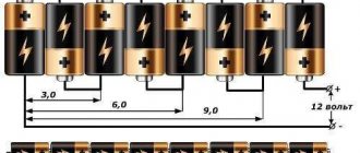
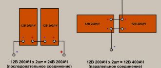
The easiest way to get 12V voltage is to connect 8 1.5V AA batteries in series.
Or use a ready-made 12V battery marked 23AE or 27A, the kind used in remote controls. Inside it is a selection of small “tablets” that you see in the photo.
We looked at a set of options for getting 12V at home. Each of them has its own pros and cons, varying degrees of efficiency, reliability and efficiency. Which option is better to use, you must choose yourself based on your capabilities and needs.
It is also worth noting that we did not consider one of the options. You can also get 12 volts from an ATX computer power supply. To start it without a PC, you need to short-circuit the green wire to any of the black ones. 12 volts are on the yellow wire. Typically, the power of a 12V line is several hundred watts and the current is tens of amperes.
Now you know how to get 12 Volts from 220 or other available values. Finally, we recommend watching a useful video on the topic:
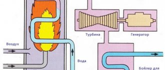
SILENCER HEAT RECEIVER
Before we look at this topic, let's talk about the rules that need to be followed:
- The power supply unit is designed to work with only one device.
- Each of the external elements must be covered with insulation. Do not touch the electronic circuitry of the unit unless there is a load connected to it or a stabilizer is not connected to it to reduce the DC current.
This sequence cannot cause death, but the unpleasant effects of electricity are guaranteed.
The value of the reducing cooler is determined by the equation:
C (microfarad) = 3200 x I (load) / root of (U input sq. - U output sq.) or C (uF) = 3200 x I (load) / root of U input
It is useless to obtain in other ways, due to the reduction in intensity from 220 to 12 V by a resistor, a lot of heat is generated, and it does not make sense to wind the inductor to obtain the required Volts, because it is very expensive and difficult to implement.
Self-production
The design of the transformer is quite simple, so it is not difficult to make it yourself. But before proceeding directly to its manufacture, it is necessary not only to prepare the material and tools, but also to perform a preliminary calculation.
How to make a step-down transformer with your own hands can be considered using a specific example. Let the task be to manufacture a converter from 220 V to 12 V with an output current of 10 A.
It is unlikely that you can make the core yourself, so it is better to use an unnecessary transformer of any type. You will need to carefully disassemble it and remove the “hardware” from there.
The next step is to make the frame. You can use various materials, for example, fiberglass. To calculate it, you can use the Power Trans program. It is worth noting that although this application can also calculate the number of turns, it is better not to use it for these purposes, due to not entirely correct results.
In the program, you can select the type of core, as well as set the cross-section of the core, windows and power of the product. Then click on calculation and get a finished drawing with dimensions. Next, all that remains is to transfer the drawing onto the textolite and cut out the required number of parts. After all the elements are prepared they are assembled into a frame.
Now you can proceed to preparing the insulating gaskets. They will be necessary to isolate the layers from each other. They are cut into strips of varnished fabric, fluoroplastic, mylar, or even thick paper, for example, which is used for baking. It is important to note that the width of the strip is made a couple of millimeters larger, and it is not recommended to mark the cutting lines with a graphite pencil (graphite conducts current).
At the last stage, the wire is prepared. Since it will be necessary to wind a 220 V 12 V 10a transformer, that is, a step-down transformer, the secondary coil will be made with a thick wire, and the primary coil with a thin wire.
Design calculation
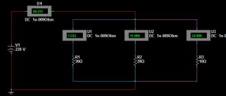
Design calculations begin by finding the power that the secondary winding must withstand. Substituting into the formula: P = U * I, the values given to the conditions b for the secondary coil, you get: P 2 = 12 * 10 = 120 W. Assuming that the efficiency of the product will be about 80% (the average value for all transformers), we can determine the primary power: P = P 2/0.8 = 120/0.8 = 150 W.
Based on the fact that power is transmitted through the core, the value of P1 will depend on the cross-section of the magnetic circuit. The cross section of the core is found from the expression: S = (P 1)½ = 150 = 12.2 cm2. Now you can find the required number of turns in the primary winding to produce one volt: W = 50/ S = 4.1. That is, for a voltage of 220 volts you will need to wind 917 turns, and for a secondary voltage - 48 turns.
You might be interested in Basic and additional means of protection in electrical installations
The current flowing through the primary coil will be equal to: I = P / U = 150/220 = 0.68 A. Hence the diameter of the primary winding wire is calculated by the formula: d = 0.8 * (I)½ will be 0.66 mm, and for the secondary - 2.5 mm. The cross-sectional area can be taken from reference tables or calculated using the formula: S = 0.8 * d 2. It will be 0.3 mm2 and 5 mm2, respectively.
If suddenly a wire of such a cross-section is difficult to get, then you can use several conductors connected to each other in parallel. In this case, their total cross-sectional area should be slightly larger than the calculated one.
Winding technique
To wind the product, the made frame must be clamped on the axis and centered . It is better to first wrap the wire around some cylindrical object. For example, a spool of thread or a piece of pipe. A coil of wire is placed opposite the clamped frame. The wire is placed on the base and made several turns around it. Then they begin to rotate the frame body. In this case, you should carefully ensure that each turn lies next to the other and does not intersect it. After each layer, two turns of insulation are applied.
Once the primary winding is wound, the wire must be brought out to the side to form a lead. The rest of the wire is cut off. Before applying the secondary winding, several layers of insulation are laid and the whole process is repeated, but with a wire of a thicker cross-section. Upon completion of the work, the free ends of the coils are soldered to the terminals. Using a tester, the coils are checked for breaking.
There are some nuances when winding that it is advisable to know. During winding, the wire may accidentally break. In this case, you will need to strip the broken ends, twist them and solder them. Carefully insulate the soldering area, for example, by placing two layers of insulating paper. When winding, to increase the electrical strength of the product, it is recommended to impregnate each layer. This prevents vibration of the wire. Epoxy or acrylic based varnishes are used as impregnation.
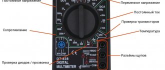
Now all that remains is to connect the transformer from 220 to 12 to the power source. The connection to it occurs in a parallel circuit. Using a multimeter you can check the output voltage. To do this, it switches to the AC signal measurement mode.
If in the future it is necessary to obtain a constant signal, then a diode bridge (rectifier) with an electrolytic capacitor (smoothing filter) is connected to the secondary winding of the transformer. But it should be taken into account that for a current of 10 amperes you will need a corresponding rectifier unit capable of withstanding such a current with a margin of about 15%.
Thus, even a novice radio amateur can make a step-down transformer on his own. The main thing is to perform the correct calculation. And the manufactured product will certainly find its application.
SUPPLY BOX ON MAINS DISTRIBUTOR
Standard and widely used sequence, used for music amplifiers and radio tape recorders. But only if you connect a good filter cooler that can make the necessary pulsation.
Plus, connect a 12 Volt stabilizing element. In its absence, the intensity will change due to current surges in the network: U output=U input* by coefficient. Transform.
Remember, the output voltage can be obtained 2-3 values higher than the output voltage of the BP-12 V, but not higher than thirty, it is determined by the capabilities of the stabilizer and its strength balances between the incoming and outgoing force.
The distributor's ability to receive 12-15 volts of varying flow. The forward tension will be slightly higher, about 1.41 times. It will approach a sine wave at the input voltage.
Basic ways to downgrade
For example, a “running” transformer with a frequency of 50 Hz with a relatively low power of 200 W, made on transformer hardware, weighs more than 1 kilogram and costs from $9–18. This not only makes the power supply bulky, but also significantly increases the cost of the device.
The transformers implement a classic scheme for reducing and then converting alternating voltage (AC) to direct voltage (DC) along the “transformer → rectifier → stabilizer” circuit.
There is a more complex scheme for constructing a “rectifier → pulse generator → transformer → rectifier → stabilizer” switching power supply, which has smaller dimensions.
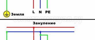
The advantage of the above schemes is galvanic isolation. When the load circuit is closed to “zero,” it prevents equipment failure and reduces the risk of electric shock to a person.
However, the smallest 12 V power supplies are transformerless power supplies, which produce:
- Use a ballast capacitor to reduce the voltage.
- Using a ballast resistor, excess voltage is suppressed.
- An unregulated autotransformer removes the required voltage and smoothes it with a choke.
Ballast capacitor
Today, installing a quenching capacitor has become a very popular means of reducing voltage among radio amateurs. This universal method is widely used to power LED lamps and in chargers of low-power batteries. Installing a radio element in the gap in the power supply network of the diode bridge allows you to obtain the required current in the electrical circuit without dissipating significant power into heat.
The circuit of a simple capacitor (transformerless) power supply with a minimum number of radio elements and a voltage of 12 V and a power of 0.18 W is as follows:
Any device designed for a constant voltage of 12 V with an operating amperage ≤ 0.15A is used as P1. Capacitor C1 is a ballast capacitor, shunted by resistor R1. It is designed to prevent electric shock from the charge accumulated on the plates of capacitor C1. With its high resistance of hundreds of kOhms, resistor R1 does not affect the flow of current through the capacitance during the working session.
However, after the power supply is turned off, a discharge current from the capacitor plates passes through the resistor for a period of time measured in several seconds. Electrolytic capacitor C2, connected in parallel to the load after the diode bridge, smoothes out the ripples of the rectified current.
The symbiosis of a rectifier and a parametric stabilizer with a regulating element will significantly reduce the dependence of the output voltage on the load resistance of the power supply unit. This modification is carried out by soldering a 12 volt zener diode in parallel to P1.
Using a resistor
The method is suitable for powering a low-current load, for example, an LED or a low-power LED lamp. The main disadvantage of a resistive circuit is low efficiency due to the dissipation of a large amount of active power spent on heating the resistor. In the simplest version, the power supply is a voltage divider with resistors installed after the diode rectifier, from the lower arm of which the voltage is removed.
Stabilization is carried out by changing the resistance of one of the divider arms: resistor values are selected in such a way as to reduce the output voltage to acceptable values.
Autotransformer or inductor with similar winding logic
The autotransformer does not have a secondary winding: the output voltage is removed from one single winding on a toroidal magnetic circuit, which is simultaneously used to supply a mains voltage of 220 V, 50 Hz.
The principle of operation is similar to LATR, only the voltage removed from the turns has a certain fixed value. Therefore, replacing a power transformer with an autotransformer increases the efficiency of the power supply and significantly reduces the size and weight of the device (other things being equal, the weight and dimensions of the transformer are 1.5 times larger than the replacement product).
Circuit diagram of an autotransformer with a fixed voltage U2.
However, an unregulated autotransformer has a significant drawback: it does not protect against voltage surges and impulses induced in the network. Low-frequency (LF) and high-frequency (HF) ripples, network noise and parasitic harmonics will be significantly reduced if a choke is installed in the output circuit. In tandem with an autotransformer, a choke with high inductance ≤ 0.5–1.0 GN is used, installed in series with the load.
The inductive element accumulates the energy of the supply network in the magnetic field of the coil and then transfers it to the load. An inductor in an electrical circuit counteracts changes in current in the electrical circuit. During a sharp drop, the coil maintains the flow of current, and during a sharp increase, it limits it, preventing it from increasing quickly. Compact AC chokes are used in boosters for energy-saving lamps and LED drivers that power LED lamps.
OPTIONS TO GET A FLOW REDUCTION FROM 24 TO 12 VOLTS, OR A STABLE VOLTAGE
To obtain a stable flow from twenty-four to twelve values, it is recommended to use a linear or pulsating stabilizing element.
The need for this appears in order to get power from a bus or truck, its power is 24 Volts.
In addition, you will acquire an already stable intensity that tends to change. Even in motorcycle wiring it rises to 14.7 V.
Therefore, this sequence can be used to recharge diode strips and light points on a car.
It is allowed to connect a load from 1 to 1.5 A. In order to increase the flow, a pass-through receiver is added, but after that the incoming voltage may drop by 0.5 V.
You can also use LDO-stabilizing elements; they are linear, but have a slight reduction in force.
For example, pulsating: AMSR-7812Z, AMSR1-7812NZ. Their connection is similar to L7812. The same methods are used to reduce the flow intensity from the laptop's power supply.
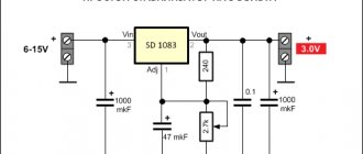
It is best to use pulsed current-reducing voltage converters, for example the LM2596 IC. The electronic circuit shows the input and output (In, Out).
In stores there is an option with a stable output voltage, as well as with a controlled one.
INCREASE FIVE VOLTS TO TWELVE
This can be done using lithium batteries with a current of 3.7-4.2 V.
If he talks about power blocks, if you have certain knowledge, you can intervene in the internal circuit.
Or make it much easier and achieve 12 V by connecting a boost converter. In the store you can purchase models with stable (12 V) or adjustable voltage (from 3.2 to 30 V) at an output of 3 A.
This converting element is sold on a ready-made electronic circuit, which has input and output marks.
An additional way is to take the MT 3608 LM 2977, the ability to raise the current to 24 V and transfers the output voltage to 2 A. In the picture below, the input and output locations are clearly visible.
Principle of operation
A transformerless transistor unit works as follows. 220 V is rectified by a bridge with a capacitor and supplied to the stabilizers. They are all made according to the same circuit, but are designed for different voltages. The first limits the network potential at 150-180 V, the second stabilizer reduces it by about 2-3 times. The third one produces the required voltage. By changing the zener diode D3, you can get a transformerless power supply, for example, 12 or 5 volts.
The RC block is a voltage divider. In its upper (according to the diagram) arm there is a capacitor C1, which represents a reactive resistance for alternating current (does not consume energy at all). At the bottom there is a diode bridge VD1-4 with a load (zener diode, transistor, microcircuit, etc.).
The input voltage comes to the divider, is rectified by the bridge and goes to the stabilizer, which limits it to the required value.