Physical definition
A resistor is an element used in an electrical circuit and does not require a power source for its operation. It is designed to transform current into voltage and vice versa. In addition, it can convert electrical energy into thermal energy and limit the amount of current. But before calculating the voltage drop across a resistor, it is advisable to understand the essence of this process.
A resistor is a very common element characterized by a number of parameters. The main ones are:
- resistance;
- the amount of energy dissipated;
- operating voltage;
- power;
- resistance to environmental influences;
- parasitic component.
A passive electrical element is indicated in the diagram as a rectangle with two terminals from the middle of its sides. In the center of the figure, power can be indicated in Roman numerals or dashes. For example, a vertical stripe indicates the element's withstand power of 1 W. The crossed out rectangle in the notation in the diagram indicates that such a resistor is variable.
Resistors can be produced with constant and variable resistance. A type of the latter are tuning elements. The only difference between them and variables is the way they are set to the desired value.
On diagrams and in technical literature, the device is designated by the Latin letter R, next to which the serial number and its denomination are indicated in accordance with the International System of Units (SI). For example, R12 5 kOhm is a five kilo-ohm resistor located in the circuit under number 12.
When manufacturing an element, a resistive layer is used, which can be film or volumetric. It is applied to a dielectric base and covered with a protective film on top.
Resistance value
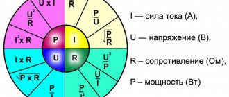
Resistance is a fundamental quantity in electrical processes. Its meaning is invariably related to current and voltage. Their general dependence is described using Ohm's law: the current strength arising in a section of the circuit is directly proportional to the potential difference between the extreme points of this section and inversely proportional to its resistance. From this law the resistance is found using the following formula:
R = U / I, where:
- R is the resistance in the circuit section, Ohm.
- I is the current strength passing through this section, A.
- U is the potential difference at the nodes of a part of the circuit, V.
In fact, the resistance of an element is determined by its physical structure and is caused by the vibrations of atoms in the crystal lattice. Therefore, all materials are classified as conductors, semiconductors and dielectrics depending on their ability to conduct electricity.
Current is the directed movement of charge carriers. For it to occur, the substance must have free electrons. If an electric field is applied to such a physical body, then the charges it moves will begin to collide with inhomogeneities in the structure. These defects are formed due to various impurities, violation of lattice periodicity, and thermal fluctuations. By hitting them, the electron expends energy, which is converted into heat. As a result, the charge loses momentum, and the magnitude of the potential difference decreases.
But Ohm's law cannot be applied to all substances. In electrolytes, dielectrics and semiconductors, a linear relationship between the three quantities is not always observed. The resistance of such substances depends on the physical parameters of the conductor, namely its length and cross-sectional area, and it is sensitive to temperature changes.
This dependence is described using the formula R = p * l / S. That is, the resistance is directly proportional to the length and inversely proportional to the area of the conductor. The value p is called resistivity and is determined by the type of material. Its meaning is taken from the reference book.
Resistor impedance
Ohm's law applies to an ideal resistor that has no parasitic resistance. The total resistance (impedance) is determined based on the equivalent circuit. Accurate calculation of resistance to reduce voltage must be carried out using other formulas. The equivalent circuit of a resistor, in addition to active impedance, also contains capacitive and inductive reactance.
The first leads to a slow accumulation of charge, which dissipates when the direction of the current changes. The larger the parasitic capacitance, the longer it takes to charge. Accordingly, the faster the current changes its direction, the lower its capacitance. The second is characterized by a magnetic field, whose appearance prevents the current from changing direction, therefore, the faster the current changes its movement, the greater the inductive reactance becomes.
Impedance is calculated using the formula : I = U/Z, where Z = (R2+(Xc-Xl)2)½. Where:
- R is the active value, R = p*l/s.
- Xc is a capacitive value, Xc = 1/w*C.
- Xl is an inductive quantity, Xl = w*C.
- w is the cyclic frequency, w = 2πƒ.
Knowing the total resistance of the resistor, you can more accurately calculate the voltage drop in it. But to measure parasitic components you will need to use highly specialized instruments. In conventional calculations, resistance is calculated taking into account only its active value, and parasitic values are taken as negligible.
Features of the current divider
Let us highlight the main features of a current divider consisting of parallel connected resistors:
- The total resistance is always less than the resistance of any resistor connected in parallel.
- Increasing the number of resistors connected in parallel leads to a decrease in the total resistance and an increase in the total current in the circuit.
- If two resistors with the same resistance are connected in parallel, then the total resistance of these resistors will be exactly two times less than the resistance of each of the resistors included in this chain.
- If resistors of the same value are used in the circuit, then the formula for the total resistance is simplified and takes the form R = R1 / N (R1 is the nominal resistance of the resistor; N is the number of resistors with the same nominal resistance).
Serial connection
This is the name for combining two or more resistors into one section of a circuit, in which their connection to each other occurs only at one point. Impedance when connected in series is defined as the sum of the resistances of each individual element: Rtotal = R1+R2+…+Rn.
Consequently, the current flowing through such a chain will become less and less after passing through a series-connected resistor. The more elements there are in the chain, the more difficult it will be for him to pass them all. Thus, its overall value is determined as Itotal = U / (R1+R2+…+Rn).
Therefore, it can be argued that in a series connection there is only one path for current to flow. The greater the number of resistors in the line, the less current will be in this section.
The drop in potential difference with this type of connection on each element will have its own meaning. It is determined by the formula URn = IRn*Rn, and the greater the impedance of the element, the more energy it will begin to release.
Useful tips Connection diagrams Principles of operation of devices Main concepts Meters from Energomer Precautions Incandescent lamps Video instructions for the master Testing with a multimeter
Current divider - calculation using formulas
For example, let’s take a scheme similar to the one discussed earlier. In a parallel section there are three resistors 30, 20 and 10 Ohms. The power supply voltage is 220 V. The Multisim program calculated the current strength in each section.
We need to calculate the current strength in different areas ourselves. The initial data is as follows:
- R1 = 30 Ohm, R2 = 20 Ohm, R3 = 10 Ohm.
- In the first case, only the voltage of the power supply U1 = 220 V (voltmeter V1) is known.
- In the second case, only the total current in the circuit is known: I4 = 40.333 A.
It is required to determine the current strength I1, I2, I3 (ammeters U1, U2, U3) in areas with resistors R1, R2, R3.
Solution:
- If the voltage of the power supply is unknown, then first of all you need to determine the sum of the resistances of all resistors connected in parallel. Each resistor carries its own current. The sum of the currents of all resistors gives the total current of the circuit: I = I1+I2+I3+…+In . Accordingly, the total conductivity of a parallel circuit is equal to the sum of its individual conductances. Conductivity is the reciprocal of resistance, so the equivalent resistance of parallel-connected resistors is determined by the following ratio: 1/R = 1/R1+1/R2+1/R3+…+1/Rn . Accordingly, 1/R = 1/30+1/20+1/10 = (2+3+6)/60 (reduced to a common denominator) = 11/60. Hence R = 60/11 = 5.45 Ohms (sum of resistors R1, R2, R3).
- Knowing the total current of the circuit and the total resistance, we find the voltage. U = I×R = 40.333×5.45 ≈ 219.8 ≈ 220 V.
- When resistors are connected in parallel, the voltage in the entire circuit and in each section is the same and equal to the voltage of the power source. Accordingly, I1 = U/R1; I2 = U/R2; I3 = U/R3 .
- I1 = 220/30 = 7.333 A.
- I2 = 220/20 = 11 A.
- I1 = 220/10 = 22 A.
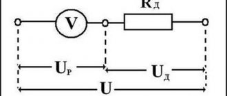
Resistive voltage divider
In general, devices of this type perform a conversion according to the formula U out = U in*K, where:
- Uin (out) – voltage at the input and output, respectively;
- K is a correction factor indicating the transmission capabilities of the node.
If we take the first example from Fig. above, to clarify the essence of the processes, Kirchhoff’s second law is suitable. In accordance with this rule, the total voltage value across series-connected resistors will be equal to the sum of the EMF on each element. Since the current does not change in a closed loop, Ohm's law can be used for calculation:
U (voltage) = I (current) * R (electrical resistance)
The lower part of the circuit (arm) is used to obtain the required change in the input parameter.
Resistor power characteristic
The power of the electric current in a section of the circuit can be found through the product of the current strength for it and the voltage in this section. The formula is as follows: P= I * U (product of current and voltage), where
P – power value (W).
The resistor does work to reduce the current, while it releases heat into the surrounding space. But if the work to limit the current is very great and heat is generated too quickly, then it will overheat and may burn out, since it will not have time to dissipate it. This point should be taken into account when selecting the resistor power
Important! The power of a resistor is a very important parameter that must be taken into account when developing electrical circuits for devices. The power of a resistor is characterized by the maximum amount of current that it can withstand without overheating or failing.
Types and principle of operation
This publication discusses in detail the resistive voltage divider. This assumes linearity of the circuit characteristics. In such circuits, the calculation of resistance to lower the voltage to the required level is simplified. When a DC source is connected, the voltages are divided in direct proportion to the values of the electrical resistances of the lower and upper arms.
Circuits with reactive characteristics
If you create a similar circuit with capacitors, then to maintain normal functionality you will have to apply a sine wave to the input. In this case, voltage distribution will also be carried out on elements with capacitive characteristics. However, this process must be considered in dynamics, taking into account the frequency and the corresponding change in amplitude. A similar technique is used when working with inductive components.
Reactance values:
- Rc=1/(2*f*π*C);
- RL=2*f*π*C.
The formulas show that the resistance of the capacitor/coil is inversely (directly) proportional to the capacitance/inductance. The values of the elements for dividing the voltage are selected accordingly.
In the presented examples, the internal load resistance is assumed to be infinitely large. For real calculations, more complex formulas with correction factors are used. The actual complex characteristics of the circuits are taken into account.
For your information. In voltage stabilizers and some other devices, the resistance of the divider arm has nonlinear parameters.
Application
The use of such circuitry in practice is demonstrated by the following examples. To calculate electrical parameters without taking into account load resistance, the manual and automated methods discussed above are suitable.
Potentiometers
If the resistor is equipped with a slider and a corresponding drive, the resistance can be changed smoothly. This solution allows you to more accurately change the output voltage compared to discrete circuits. The main disadvantage is the complexity of the design, which, in addition to increasing the cost, reduces reliability. It is necessary to ensure the tightness of the working area to prevent contamination and prevent corrosion processes.
Potentiometer circuit diagram
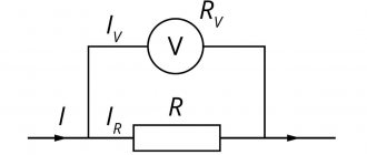
Resistive sensors
This option takes advantage of the ability of some materials to increase/decrease electrical resistance under the influence of temperature, light flux, and other external influences. A sensor created on the basis of these principles is installed in the divider arm. Changes in the corresponding parameters are monitored by the output voltage level.
Feedback circuits in amplifiers
This solution provides the required gain. In the diagram below, this parameter will never be lower than one. To increase the conversion level, increase the value of resistance R2 relative to R1.
Voltage divider in the feedback circuit
The simplest electrical filters
For filtering, resistors R1 or R2 are replaced with a capacitor. In the first version, the device allows high-frequency components to pass through unhindered. When the frequency decreases to a certain level, the reactance increases, preventing the passage of current. Similarly, changes are made in the lower arm of the divider in order to cut off low frequencies.
Voltage amplifier
A variable resistor changes the signal level to obtain the required sound volume. Such devices use elements with a logarithmic characteristic of resistance change, which corresponds well to the natural mechanism of perception by the human hearing organs.
Parametric voltage stabilizer
In such circuits, the lower arm of the divider can be created using a zener diode. Its current-voltage characteristics are chosen in such a way that the output voltage maintains the desired value when the input parameters change.
How to lower the voltage from 12 to 5 volts using a microcircuit
Nothing fundamentally changes in this case either. If we compare this reduction option through a microcircuit with the option using a resistor. In fact, everything is the same here, except that useful “intelligent” features are added for adjusting the internal resistance of the microcircuit based on the current consumption. That is, as we understood from the paragraph above, depending on the consumption current, the calculated resistance should “float”. This is exactly what happens in a microcircuit when the resistance is adjusted to the load in such a way that the output of the microcircuit is always the same supply voltage! Well, plus there are such “useful buns” as protection against overheating and short circuit. As for microcircuits, so-called 5-volt voltage stabilizers, these could be: LM7805, KREN142EN5A. The connection is also very simple.
Of course, for the microcircuit to operate efficiently, we place it on a radiator. The stabilization current is limited to 1.5 -2 A. These are the principles of reducing the voltage from 12 to 5 volts. Now, once you understand them, you can easily calculate what resistance should be installed or how to select a microcircuit to obtain any other lower voltage. It remains to say a few words about PWM.
Wide pulse modulation is a very promising and, most importantly, highly efficient method of powering the load, but again with its pitfalls. The whole essence of PWM comes down to delivering in pulses a supply voltage that, together with moments of no voltage, will provide power and average voltage sufficient to operate the load. And here there can be problems if you connect the power source from one device to another. Well, the simplest problems are the lack of those characteristics that are stated. Possible interference and unstable operation. In the worst case, a PWM power supply can completely burn out a device for which it was not originally intended!