The USB interface began to be widely used about 20 years ago, to be precise, since the spring of 1997. It was then that the universal serial bus was implemented in hardware in many personal computer motherboards. Currently, this type of connecting peripherals to a PC is a standard, versions have been released that have significantly increased the data exchange speed, and new types of connectors have appeared. Let's try to understand the specifications, pinouts and other features of USB.
What are the advantages of Universal Serial Bus?
The introduction of this connection method made it possible:
- Quickly connect various peripheral devices to your PC, from the keyboard to external disk drives.
- Make full use of Plug&Play technology, which simplifies the connection and configuration of peripherals.
- Refusal of a number of outdated interfaces, which had a positive impact on the functionality of computing systems.
- The bus allows not only to transfer data, but also to supply power to connected devices, with a load current limit of 0.5 and 0.9 A for the old and new generations. This made it possible to use USB to charge phones, as well as connect various gadgets (mini fans, lights, etc.).
- It has become possible to manufacture mobile controllers, for example, a USB RJ-45 network card, electronic keys for entering and exiting the system
Length of cable
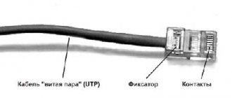
The maximum cable length should not exceed 5 meters. The cable length can be increased to 30 meters if the active component (hub, etc.) is installed every 5 meters. The signal propagation time between the end device and the host is too long. Host (PC connection) provides a maximum current of 500mA at 5V operating voltage or 900mA with USB 3.0.
The usual pinout of the internal wires of a USB cable by color:
- Red: A contact that carries positively charged electrical energy. Additionally, it has a 5 volt DC charge.
- Black: ground wire.
- White: positive wire for information.
- Green: negative for information.
If the wiring inside the cord is a combination of other shades:
- Orange: Has the same functionality as the red wire (5 volts DC through which a positive charge passes).
- White: in this version, the USB cable is grounding.
- Green: data transfer plus.
- Blue: data transmission minus.
If the cable uses completely different colors, you should study the instructions from the manufacturer.
Types of USB connectors - main differences and features
There are three specifications (versions) of this type of connection that are partially compatible with each other:
- The very first version that has become widespread is v 1. It is an improved modification of the previous version (1.0), which practically did not leave the prototype phase due to serious errors in the data transfer protocol. This specification has the following characteristics:
- Dual-mode data transfer at high and low speed (12.0 and 1.50 Mbps, respectively).
- Possibility of connecting more than a hundred different devices (including hubs).
- The maximum cord length is 3.0 and 5.0 m for high and low transfer speeds, respectively.
- The rated bus voltage is 5.0 V, the permissible load current of the connected equipment is 0.5 A.
Today this standard is practically not used due to its low throughput.
- The dominant second specification today... This standard is fully compatible with the previous modification. A distinctive feature is the presence of a high-speed data exchange protocol (up to 480.0 Mbit per second).
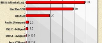
A clear demonstration of the advantages of USB 2.0 over other interfaces (transfer speed 60 MB per second, which corresponds to 480 Mbit per second).
Thanks to full hardware compatibility with the younger version, peripheral devices of this standard can be connected to the previous modification. True, the throughput will decrease up to 35-40 times, and in some cases more.
Since these versions are fully compatible, their cables and connectors are identical.
Please note that, despite the bandwidth specified in the specification, the actual data exchange speed in the second generation is somewhat lower (about 30-35 MB per second). This is due to the implementation of the protocol, which leads to delays between data packets. Since modern drives have a read speed four times higher than the throughput of the second modification, that is, it does not meet current requirements.
- The 3rd generation universal bus was developed specifically to solve problems of insufficient bandwidth. According to the specification, this modification is capable of exchanging information at a speed of 5.0 Gbit per second, which is almost three times the reading speed of modern drives. Plugs and sockets of the latest modification are usually marked blue to facilitate identification of belonging to this specification.
USB 3.0 connectors have a characteristic blue color.
Another feature of the third generation is an increase in the rated current to 0.9 A, which allows you to power a number of devices and eliminate the need for separate power supplies for them.
As for compatibility with the previous version, it is partially implemented; this will be discussed in detail below.
USB Type C pinout
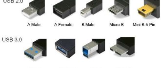
USB Type is divided into A, B, B (mini), B (micro) and C.
USB Type A and B have 4 contacts each:
- +5V;
- D-;
- D+;
- GND.
To USB Type B mini and micro, as well as Type C, another contact is added - ID.
USB has a “plug” and a “socket”. On the pinout, the “socket” is on the left and the “plug” is on the right.
Notable Features of USB-C:
- There is a changeover connector. It is designed in such a way that the plug can be moved relative to the socket.
- There is support for USB 2.0, 3.0 and 3.1 Gen 2, as well as third-party protocols (for example, HDMI), in alternative mode.
Thanks to this, the devices are able to independently negotiate and determine the required power flow through the interface.
- USB Type C is capable of transmitting images and audio
- It can withstand high currents, so it is possible to power many devices at the same time.
Taking into account all the advantages described above, USB Type-C can be called a truly universal connector of the future. It is capable of replacing almost any existing connector. Now, for example, the Apple company produces laptop models equipped only with Type-C connectors.
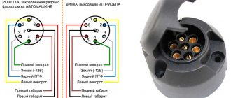
Pinout of micro USB connector for charging the phone
Everyone has encountered a problem when the charger refuses to charge the phone, no matter how you twist it. There can be many options for this behavior: from burning out the insides of the adapter to lack of contact in the connector.
The USB Consortium has adopted a new standard known as micro-B, a smaller USB connector that will be used primarily on small portable devices where space is limited (such as cell phones). The micro USB connector is approximately half the height of the mini USB connector, allowing thinner devices to have USB access.
GSMA has accepted it as a universal charging solution, so 90% of new mobile phones will have this connector.
The pinout shows micro USB, which Samsung often uses. Here you can see that there are 5 contacts (ID is present), the counting goes from right to left, and there is also a jumper between the green (D+) and white (D-) contacts.
In the same Samsung you can find a jumper not only on white (D-) and green (D+), but also on black (GND) and purple (ID) using a resistor.
This is necessary in order to make the required voltage (this figure is different for all devices, but in most cases the resistance should be up to 200 kOhm).
Thanks to this, the device understands when to supply current and in what quantity.
Classification and pinout
Connectors are usually classified by type, there are only two of them:
- A is a plug connected to the female socket installed on the PC system board or USB hub. Using this type of connection, you can connect a USB flash drive, keyboard, mouse, etc. These connections are fully compatible between the initial version and the second generation. With the latest modification, compatibility is partial, that is, devices and cables from earlier versions can be connected to third-generation sockets, but not vice versa.
Type A connectors - B – plug for connecting to a socket installed on a peripheral device, for example, a printer. The dimensions of the classic type B do not allow it to be used for connecting small-sized devices (for example, tablets, mobile phones, digital cameras, etc.). To correct the situation, two standard reduced modifications of type B were adopted: mini and micro USB.
Note that such convectors are compatible only between earlier modifications.
Various Type B Connector Models
In addition, there are extension cables for the ports of this interface. At one end there is a type A plug, and at the other there is a socket for it, that is, in fact, a “female” - “male” connection. Such cords can be very useful, for example, to connect a flash drive without crawling under the table to the system unit.
USB Extension Cable
Now let's look at how contacts are wired for each of the types listed above.
Pinout of connectors on
Plug
When looking at pinout diagrams, you need to understand all the markings present on it.
Standard marks:
- Connector type – active or passive (i.e. A or B).
- The connection format is a female socket (port, M) or a male socket (plug, F).
- Size format – standard, Microusb or Mini.
According to the color scheme, the contacts should be located in the direction from left to right:
- red – positive, with a maximum DC layer of 500 ml-amp;
- white and green – data- and data+;
- black – “minus” or “ground”.
MicroUSB and Mini differ in the following pin arrangement:
- red, white and green - no differences;
- ID - in connector B it will not be active and connected, in A it will need to be shorted to the black ground contact.
USB 2.0 connector pinout (types A and B)
Since the physical plugs and sockets of early versions 1.1 and 2.0 do not differ from each other, we will present the wiring of the latter.
Figure 6. Wiring the plug and socket of type A connector
Designation:
- A – nest.
- B – plug.
- 1 – power supply +5.0 V.
- 2 and 3 signal wires.
- 4 – mass.
In the figure, the coloring of the contacts is shown according to the colors of the wire, and corresponds to the accepted specification.
Now let's look at the wiring of the classic socket B.
Wiring of plug and socket type B
Designation:
- A – plug connected to the socket on peripheral devices.
- B – socket on a peripheral device.
- 1 – power contact (+5 V).
- 2 and 3 – signal contacts.
- 4 – ground wire contact.
The colors of the contacts correspond to the accepted colors of the wires in the cord.
Micro-USB connector pinout
The Micro-USB cable has 5-pin connectors. A separate mounting wire in insulation of the desired color is supplied to them. To ensure that the plug fits accurately and tightly into the socket, the upper shielding part has a special chamfer. The micro USB pins are numbered 1 to 5 and read from right to left.
The pinouts of micro- and mini-USB connectors are identical; they are presented in the table:
| Wire number | Purpose | Color |
| 1 | VCC power supply 5V | red |
| 2 | data | white |
| 3 | data | green |
| 4 | ID function, for type A shorted to ground | |
| 5 | grounding | black |
USB 3.0 pinout (types A and B)
In the third generation, peripheral devices are connected via 10 (9 if there is no shielding braid) wires; accordingly, the number of contacts is also increased. But they are located in such a way that it is possible to connect devices of earlier generations. That is, the +5.0 V contacts, GND, D+ and D-, are located in the same way as in the previous version. The wiring for Type A socket is shown in the figure below.
Figure 8. Pinout of Type A connector in USB 3.0
Designation:
- A – plug.
- B – nest.
- 1, 2, 3, 4 – connectors fully correspond to the pinout of the plug for version 2.0 (see B in Fig. 6), the colors of the wires also match.
- 5 (SS_TX-) and 6 (SS_TX+) connectors for data transmission wires via the SUPER_SPEED protocol.
- 7 – ground (GND) for signal wires.
- 8 (SS_RX-) and 9 (SS_RX+) connectors for data receiving wires using the SUPER_SPEED protocol.
The colors in the figure correspond to those generally accepted for this standard.
As mentioned above, a plug from an earlier model can be inserted into the socket of this port; accordingly, the throughput will decrease. As for the plug of the third generation of the universal bus, it is impossible to insert it into the sockets of the early release.
Now let's look at the pinout for the type B socket. Unlike the previous type, such a socket is incompatible with any plug of earlier versions.
Wiring USB 3.0 type B
Designations:
A and B are plug and socket, respectively.
Digital signatures for contacts correspond to the description in Figure 8.
The color is as close as possible to the color markings of the wires in the cord.
Micro USB connector pinout
To begin with, we present the wiring for this specification.
Micro USB v 2.0 connector wiring
As can be seen from the figure, this is a 5 pin connection; both the plug (A) and socket (B) have four contacts. Their purpose and digital and color designation correspond to the accepted standard, which was given above.
Description of the micro USB connector for version 3.0.
For this connection, a characteristically shaped 10 pin connector is used. In fact, it consists of two parts of 5 pin each, and one of them fully corresponds to the previous version of the interface. This implementation is somewhat confusing, especially considering the incompatibility of these types. Probably, the developers planned to make it possible to work with connectors of earlier modifications, but subsequently abandoned this idea or have not yet implemented it.
MicroUSB connector layout for version 3.0
The figure shows the pinout of the plug (A) and the appearance of the micro USB socket (B).
Contacts 1 to 5 fully correspond to the second generation micro connector, the purpose of the other contacts is as follows:
- 6 and 7 – data transmission via high-speed protocol (SS_TX- and SS_TX+, respectively).
- 8 – mass for high-speed information channels.
- 9 and 10 – data reception via high-speed protocol (SS_RX- and SS_RX+, respectively).
Mini USB pinout
This connection option is used only in early versions of the interface; in the third generation this type is not used.
Mini USB connector pinout
As you can see, the wiring of the plug and socket is almost identical to the micro USB, respectively, the color scheme of the wires and the contact numbers are also the same. Actually, the differences are only in shape and size.
In this article we have presented only standard types of connections; many manufacturers of digital equipment practice introducing their own standards; there you can find connectors for 7 pin, 8 pin, etc. This introduces certain difficulties, especially when the question arises of finding a charger for a mobile phone. It should also be noted that products are in no hurry to tell how the USB pinout is done in such contactors. But, as a rule, this information is easy to find on thematic forums.