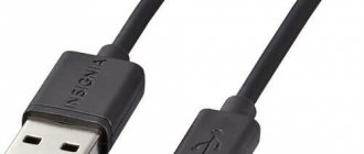
USB cable pinout refers to the description of the internals of the Universal Serial Bus. This device is used to transfer data and charge batteries of any electronic devices: mobile phones, players, laptops, tablet computers, tape recorders and other gadgets.
Carrying out high-quality pinouts requires knowledge and ability to read diagrams, orientation in the types and types of connections, you need to know the classification of wires, their colors and purpose. Long-term and uninterrupted operation of the cable is ensured by the correct wire connection of the 2 USB and mini-USB .
Types of USB connectors, main differences and features
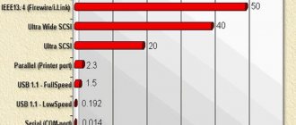
The Universal Serial Bus comes in 3 versions - USB 1.1, USB 2.0 and USB 3.0. The first two specifications are completely compatible with each other; bus 3.0 is partially compatible.
USB 1.1 is the first version of the device used for data transfer. The specification is used only for compatibility, since 2 operating modes for data transfer (Low-speed and Full-speed) have a low speed of information exchange. Low-speed mode with a data transfer rate of 10-1500 Kbps is used for joysticks, mice, and keyboards. Full-speed is used in audio and video devices.
A third operating mode has been added to USB 2.0 - High-speed for connecting information storage devices and video devices of a higher organization. The connector is marked with HI-SPEED on the logo. The information exchange speed in this mode is 480 Mbit/s, which is equal to the copying speed of 48 MB/s.
In practice, due to the design and implementation features of the protocol, the throughput of the second version turned out to be less than declared and amounts to 30-35 MB/s. The 1.1 and 2nd generation Universal Bus specification cables and connectors are identical in configuration.
The third generation universal bus supports a speed of 5 Gbps, equal to a copy speed of 500 MB/s. It is available in blue, which makes it easier to determine whether the plugs and sockets belong to the advanced model. Bus 3.0 current increased from 500 mA to 900 mA. This feature allows you not to use separate power supplies for peripheral devices, but to use the 3.0 bus to power them.
Compatibility of specifications 2.0 and 3.0 is partially achieved.
Educational program on temperatures and soldering locations
Many beginners set temperatures on soldering stations above 400 °C. This is the most critical and dangerous mistake. At such temperatures, not a single connector will be intact. The plastic base melts, and the contacts can be closed after such frying.
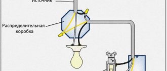
Soldering location and environment
The soldering location is a very important point. If you solder on a metal plate or stand, the board will transfer the incoming heat from the hair dryer, i.e. the metal will essentially act as a heat sink. This is critical because Because of this, many people increase the temperature to 360 °C or higher, and for this reason overheating occurs. When the board is already warming up from this temperature, a critical temperature reaches the connector itself and the top layer of the board. That is, in fact, solder melts from 180 to 230 °C (lead-containing solders) or from 180 to 250 °C (lead-free solders). And when the board is heated to the conventional melting temperature of the solder, the part itself or the connector, or the top layer of the board is affected by a much higher temperature.
Therefore, it is best to place the board on a wooden board with several layers of napkins on it. There should also be few of them (the surface will no longer be smooth, which in turn will lead to poor surface tension of the solder).
Wood and paper heat up much earlier and release less heat into the environment. Also, soldering of the micro USB connector can be done using the so-called third hand. This is a tabletop stand that has alligators attached to it for mounting the board. The board will be suspended and the surrounding air will warm up much faster.
Classification and pinout
When describing and designating tables of USB connectors, it is accepted by default that the view is shown from the outside, working side. If the view is from the installation side, this is specified in the description. In the diagram, the insulating elements of the connector are marked in light gray, the metal parts are marked in dark gray, and the cavities are marked in white.
Despite the fact that the serial bus is called universal, it is represented by 2 types. They perform different functions and provide compatibility with devices with improved characteristics.
Type A includes active, power supply devices (computer, host), type B includes passive, connected equipment (printer, scanner). All sockets and plugs of the second generation and version 3.0 type A buses are designed to work together. The Gen3 Type B jack connector is larger than what is needed for the 2.0 Type B plug, so a device with a Gen 2.0 Type B connector is connected using only a USB 2.0 cable. Connection of external equipment with modification 3.0 type B connectors is carried out using cables of both types.
Classic Type B connectors are not suitable for connecting small electronic equipment. Connecting tablets, digital equipment, and mobile phones is done using miniature Mini-USB connectors and their improved Micro-USB modification. These connectors have reduced plug and socket sizes.
The latest modification of USB connectors is type C. This design has identical connectors at both ends of the cable and is characterized by faster data transfer and greater power.
What are the advantages of Universal Serial Bus?
The introduction of this connection method made it possible:
- Quickly connect various peripheral devices to your PC, from the keyboard to external disk drives.
- Make full use of Plug&Play technology, which simplifies the connection and configuration of peripherals.
- Refusal of a number of outdated interfaces, which had a positive impact on the functionality of computing systems.
- The bus allows not only to transfer data, but also to supply power to connected devices, with a load current limit of 0.5 and 0.9 A for the old and new generations. This made it possible to use USB to charge phones, as well as connect various gadgets (mini fans, lights, etc.).
- It has become possible to manufacture mobile controllers, for example, a USB RJ-45 network card, electronic keys for entering and exiting the system
It will be interesting➡ What is active power?
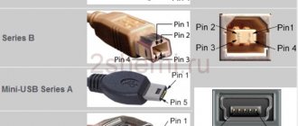
Pinout of USB 2.0 connector types A and B
Classic connectors contain 4 types of contacts; mini and micro formats contain 5 contacts. Wire colors in USB 2.0 cable:
- +5V (red VBUS), voltage 5 V, maximum current 0.5 A, intended for power supply;
- D- (white) Data-;
- D+ (green) Data+;
- GND (black), voltage 0V, used for grounding.
For mini format: mini-USB and micro-USB:
- Red VBUS (+), voltage 5 V, current 0.5 A.
- White (-), D-.
- Green (+), D+.
- ID – for type A it is closed to GND to support the OTG function, but for type B it is not used.
- Black GND, voltage 0V, used for grounding.
Most cables have a Shield wire; it has no insulation and is used as a shield. It is not marked and is not assigned a number. The universal bus has 2 types of connectors. They are designated M (male) and F (female). Connector M (male) is called a plug, it is inserted, connector F (female) is called a socket, it is inserted into it.
USB 3.0 pinout types A and B
Bus version 3.0 has a 10 or 9 wire connection. 9 pins are used if Shield wire is missing. The contacts are arranged in such a way that devices of earlier modifications can be connected.
USB 3.0 wiring:
- A – plug;
- B – socket;
- 1, 2, 3, 4 – contacts that match the pinout of the contacts in specification 2.0, have the same color scheme;
- 5, 6 contacts for data transmission via the SUPER_SPEED protocol are designated SS_TX- and SS_TX+, respectively;
- 7 – grounding GND;
- 8, 9 – contact pads of wires for receiving data via the SUPER_SPEED protocol, contact designation: SS_RX- and SS_RX+.
Micro-USB connector pinout
The Micro-USB cable has 5-pin connectors. A separate mounting wire in insulation of the desired color is supplied to them. To ensure that the plug fits accurately and tightly into the socket, the upper shielding part has a special chamfer. The micro USB pins are numbered 1 to 5 and read from right to left.
The pinouts of micro- and mini-USB connectors are identical; they are presented in the table:
| Wire number | Purpose | Color |
| 1 | VCC power supply 5V | red |
| 2 | data | white |
| 3 | data | green |
| 4 | ID function, for type A shorted to ground | |
| 5 | grounding | black |
The shielding wire is not soldered to any contact.
Mini-USB pinout
Mini-A and Mini-B connectors appeared on the market in 2000, using the USB 2.0 standard. Today they are little used due to the emergence of more advanced modifications. They have been replaced by microconnectors and Type C USB models. The mini connectors use 4 shielded wires and an ID function. 2 wires are used for power: supply +5 V and ground GND. 2 wires for receiving and sending differential data signals, designated D+ and D-pin. Data+ and Data- signals are transmitted over twisted pair cable. D+ and D- always work together, they are not separate simplex compounds.
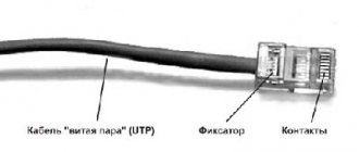
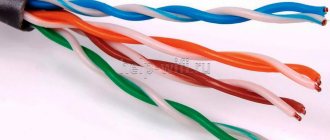
USB connectors use 2 types of cables:
- shielded, 28 AWG twisted, 28 AWG or 20 AWG untwisted;
- unshielded, 28 AWG untwisted, 28 AWG or 20 AWG untwisted.
The cable length depends on the power:
Many manufacturers of digital equipment develop and equip their products with connectors of a different configuration. This may cause difficulty charging your mobile phone or other devices.
Most likely, you have already encountered a problem when the required USB adapter is not at hand. There are different cases: lost; broken; out of stock; not enough in length, etc. This article suggests fixing this problem yourself. Knowing the pinout (soldering) of the contacts and having the skills to use a soldering iron, you can easily fix this problem. Today, USB, USB-mini and USB-micro are the most popular connectors in digital technology. Today, neither mobile phones nor most gadgets can do without them.
Below is a table of USB contacts with the purpose of the connectors, their colors and numbers.
Let’s immediately define one more concept. There is another type of USB. Let's remember what an adapter from a computer to a printer or scanner looks like. The naked eye can see that the connectors themselves on this adapter are different. So, the connector that is inserted into the computer is called active and is designated A. The connector that is inserted into a printer or scanner, as well as possibly other peripheral devices, is called passive and is designated B.
Read also: How to assemble a box from plywood
Let's take a closer look at the purpose of the wires
USB 2.0 1. +5V (red) conductor intended for power supply. The maximum supply current does not exceed 500mA, voltage +5V relative to GND (Ground). 2. D- (white) Data - 3. D- (green) Data + 4. GND (black) - common wire intended for Ground (0 Volts)
Mini-USB and micro-USB connectors For these connectors, the main difference from USB is not only its size, but also the presence of an additional contact. 1. Red - VBUS. 2. White D- (Data -). 3. Green D+ (Data +). 4. ID - it is not used in passive type “B” connectors. In active type "A" connectors, it is shorted to Ground (GND) to support the "OTG" function. 5. Black - Ground (GND).
It should also be noted that the cable almost always contains a Shield wire (without insulation). It acts as a screen (braid). It is not marked in any way and does not have its own number.
Now one more concept. You've most likely observed how a USB "extender" works. It is immediately noticeable that the connectors are different. As with all other connectors, USB also has a female-male concept. M (male) - called plug (male) F (female) - called socket (mother)
Now, we come to the complete table of USB connectors. Knowing concepts such as F and M, A and B, colors and numbers of wires, we can easily determine how the connector that you are going to solder, repair, or extend is soldered. The order and numbers of contacts are indicated on the working side.
Features of cable wiring on connector contacts
There are no special technological nuances associated with soldering cable conductors on the contact pads of connectors. The main thing in this process is to ensure that the color of the pre-insulated cable conductors matches the specific contact (pin).
Color coding of conductors inside the cable assembly used for USB interfaces. Shown from top to bottom, respectively, is the color scheme of cable conductors for specifications 2.0, 3.0 and 3.1
Also, if you are wiring modifications of outdated versions, you should take into account the configuration of the connectors, the so-called “male” and “female”.
The conductor soldered on the male contact must match the soldering on the female contact. Take, for example, the option of wiring the cable to USB 2.0 pins.
The four working conductors used in this embodiment are usually marked in four different colors:
- red;
- white;
- green;
- black.
Accordingly, each conductor is soldered onto a pad marked with a connector specification of a similar color. This approach greatly simplifies the work of the electronics engineer and eliminates possible errors during the desoldering process.
A similar soldering technology is applied to connectors of other series. The only difference in such cases is the larger number of conductors that have to be soldered. To simplify your work, it is convenient to use special tools - a reliable soldering iron for soldering wires at home and a stripper for removing insulation from the ends of the wires.
Regardless of the connector configuration, screen conductor soldering is always used. This conductor is soldered to the corresponding contact on the connector; Shield is a protective screen.
There are frequent cases of ignoring the protective screen, when “experts” do not see the point in this conductor. However, the lack of a screen dramatically reduces the performance of the USB cable.
Therefore, it is not surprising when, with a significant length of cable without a screen, the user experiences problems in the form of interference.
Wiring the connector with two conductors to organize a power line for the donor device. In practice, different wiring options are used, based on technical needs.
There are different options for soldering a USB cable, depending on the configuration of the port lines on a particular device.
For example, to connect one device to another in order to obtain only a supply voltage (5V), it is enough to solder only two lines on the corresponding pins (contacts).