Typically, a computer power supply has 6 or 5 connectors: 4 (4 pin) for powering drives and 2 (6 pin) (AT) or 1 (20 pin) (ATX) for the motherboard.
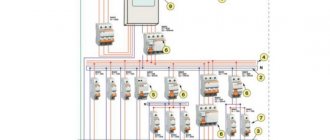
Motherboard power connectors
AT motherboard power connectors
| P8 № | Signal | Color |
| 1 | Power Good | orange |
| 2 | +5V | red |
| 3 | +12V | yellow |
| 4 | -12V | blue |
| 5 | frame | black |
| 6 | frame | black |
№
| Signal | Color | |
| 1 | frame | black |
| 2 | frame | black |
| 3 | -5V | white |
| 4 | +5V | red |
| 5 | +5V | red |
| 6 | +5V | red |
ATX motherboard power connector
| № | Signal | № | Signal |
| 1* | +3.3 V | 11 | +3.3 V |
| 2 | +3.3 V | 12 | -12 V |
| 3 | Earth | 13* | Earth |
| 4 | +5 V | 14* | Power Supply On |
| 5 | Earth | 15 | Earth |
| 6 | +5 V | 16 | Earth |
| 7 | Earth | 17 | Earth |
| 8 | Power Good | 18 | -5 V |
| 9 | +5 V Standby | 19 | +5 V |
| 10 | +12 V | 20 | +5 V |
Drive power connector
| № | Signal | Color |
| 1 | +12V | yellow |
| 2 | frame | black |
| 3 | frame | black |
| 4 | +5V | red |
Keyboard connectors
Attention! Contacts are not numbered in a circle; pay attention to the number next to the contact.
| DIN5 | PS/2 | |
| № | Signal | Purpose |
| 1 | Clock frequency | Exit |
| 2 | Data line | Enter exit |
| 3 | Reset | — |
| 4 | Frame | Entrance |
| 5 | +5V | Entrance |
| Signal | Enter exit | |
| 1 | Data line | Enter exit |
| 2 | Not connected | Reserve |
| 3 | Frame | Entrance |
| 4 | +5V | Entrance |
| 5 | Clock frequency | Exit |
| 6 | Not connected | Reserve |
Connector pinout pinout
Even such an attractive connector as SCART cannot be used indefinitely. It was replaced by an S-Video connection. It is still widely used in various technologies. To connect to SCART, you can use widely used adapters. The wiring diagram is shown in the picture below.
But an even simpler solution is becoming more widespread - RCA. Separate connection involves the use of yellow, red and white plugs. The yellow and white lines are responsible for stereo audio. The red channel supplies the video signal to the TV. Wiring into “tulips” is carried out according to the diagram shown in the following photo.
Quite often you have to solve another problem - how to connect the old connector and modern HDMI. In this case, you won’t be able to limit yourself to conductors and adapters. You will have to use a device that will “translate” HDMI digital signals into analog and vice versa. Independent production of such equipment is impossible or extremely difficult.
For SCART connectors, see below.
USB cable connector
| № | Signal | № | Signal |
| A1 | Vcc | B1 | Vcc |
| A2 | Port0 data+ | B2 | Port1 data+ |
| A3 | Port0 data- | B3 | Port1 data- |
| A4 | GND | B4 | GND |
RJ-45 connector (for twisted pair connection)
(the cable is directed away from the viewer)
When connecting a computer to a hub, the “normal” layout is used. When cascading hubs or when connecting a computer to a computer (without a hub), the “uplink” layout is used at one end of the cable, and the “normal” layout at the other.
| № | Fine | uplink |
| 1 | brown | brown |
| 2 | white-brown | white-brown |
| 3 | green | orange |
| 4 | white-blue | white-blue |
| 5 | blue | blue |
| 6 | white-green | white-orange |
| 7 | orange | green |
| 8 | white-orange | white-green |
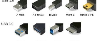
Pinout of USB connectors in a PC
Pinout of USB connectors 1.0-2.0 (Universal Serial Bus).
USB 2.0 Series A, B and Mini
USB 2.0 Micro USB
USB 2.0 on motherboard
Motherboard connector pinout for USB 2.0 front panel
USB 3.0 connector diagram
Pinout of USB 3.0 connectors (Universal Serial Bus).
USB 3.0 Series A, B, Micro-B and Powered-B. The Powered-B series differs from the B series in that it has 2 additional pins available that serve to transmit additional power, thus the device can receive up to 1000 mA of current. This eliminates the need for an additional power source for low-power devices.
USB 3.0 on motherboard
Motherboard connector pinout for USB 3.0 front panel
- Read more about micro USB here
Cable for connecting drives
Cores 10 to 16 are twisted - necessary to identify the drive.
The odd numbered contacts are the body.
| № | Enter exit | Signal | Meaning |
| 2 | Entrance | High/normal density | High/Regulatory Density |
| 4 | Entrance | Unused | Manufacturer Specification |
| 6 | Entrance | Unused | Manufacturer Specification |
| 8 | Exit | Index | Index Hole Identification |
| 10 | Entrance | Motor Enable 0 | Drive A motor: enabled |
| 12 | Entrance | Drive Select 1 | Activating drive B: |
| 14 | Entrance | Drive Select 0 | Activating drive A: |
| 16 | Entrance | Motor Enable 1 | Drive B motor: enabled |
| 18 | Entrance | Direction Select | Specifying the direction for the head |
| 20 | Entrance | Step | Impulse for head movement |
| 22 | Entrance | Write Data | Data recording |
| 24 | Entrance | Write Gate | Signal to overwrite data |
| 26 | Exit | Track 00 | The head is on the zero track |
| 28 | Exit | Write Protect | The presence of disk write protection |
| 30 | Exit | Read Data | Reading data |
| 32 | Entrance | Side Select | First or second side access |
| 34 | Exit | Drive Status | Drive ready |
Interfaces
Most GPIOs have additional capabilities, since pins from other microcontroller systems are connected to them, you are already familiar with them from the previous lesson:
- ADC (ADC, analog-to-digital converter) – green ADC* on the pinout
- UART (communication interface) – blue TXD and RXD on pinout
- Timer outputs , also known as PWM pins, are light purple OC*A and OC*B , where * is the timer number
- SPI (communication interface) – blue SS , MOSI , MISO , SCK
- I2C (communication interface) – blue SDA and SCL
- INT (hardware interrupts) – pink INT0 and INT1 , as well as PCINT* – PinChangeInterrupt
Cable for connecting IDE devices
| Contact | Enter exit | Signal | Meaning |
| 1 | Exit | Reset | Reset |
| 2 | — | GND | Frame |
| 3 | Enter exit | HD7 | Data line 7 |
| 4 | Enter exit | HD8 | Data line 8 |
| 5 | Enter exit | HD6 | Data line 6 |
| 6 | Enter exit | HD9 | Data line 9 |
| 7 | Enter exit | HD5 | Data line 5 |
| 8 | Enter exit | HD10 | Data line 10 |
| 9 | Enter exit | HD4 | Data line 4 |
| 10 | Enter exit | HD11 | Data line 11 |
| 11 | Enter exit | HD3 | Data line 3 |
| 12 | Enter exit | HD12 | Data line 12 |
| 13 | Enter exit | HD2 | Data line 2 |
| 14 | Enter exit | HD13 | Data line 13 |
| 15 | Enter exit | HD1 | Data line 1 |
| 16 | Enter exit | HD14 | Data line 14 |
| 17 | Enter exit | HD0 | Data line 0 |
| 18 | Enter exit | HD15 | Data line 15 |
| 19 | — | GND | Frame |
| 20 | — | KEY | Connector key (missing) |
| 21 | — | Reserved | Reserved |
| 22 | — | GND | Frame |
| 23 | Exit | IOW | Reading strobe |
| 24 | — | GND | Frame |
| 25 | Exit | IOR | Recording strobe |
| 26 | — | GND | Frame |
| 27 | Entrance | IOCHRDY | I/O Channel Ready |
| 28 | Exit | ALE | Address strobe |
| 29 | — | Reserved | Reserved |
| 30 | — | GND | Frame |
| 31 | Entrance | IRQ14 | Interrupt Request |
| 32 | Entrance | HIO16 | Sign of access to a 16-bit port |
| 33 | Exit | HA1 | Address line 1 |
| 34 | Enter exit | Reserved | Reserved |
| 35 | Exit | HA0 | Address line 0 |
| 36 | Exit | HA2 | Address line 2 |
| 37 | Exit | CS0 | Select Disc 1 |
| 38 | Exit | CS1 | Select disc 2 |
| 39 | Enter exit | ACTIV | Confirming drive selection |
| 40 | — | GND | Frame |
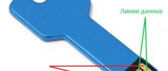
Pinout of USB type connectors.
- the first wire (red), it is supplied with a DC supply voltage of +5 V;
- the second contact (white), it is used to transmit information (D-);
- the third wire (green), it is also intended for transmitting information (D+);
- the fourth contact (black), zero supply voltage is supplied to it, it is also called the common wire.
- The first four pins are completely consistent with the 2.0 standard, so let's move on.
- The fifth pin (blue) is used to transmit information with a minus sign of USB3 (StdA_SSTX).
- The sixth pin is similar to the fifth pin, but with a plus sign (yellow).
- Seventh – additional grounding.
- The eighth pin (purple) is for receiving USB3 data (StdA_SSRX) with a minus sign.
- And finally, the last ninth (orange) is the same as the seventh pin, only with a plus sign.
Wallpapering walls with your own hands, and how to glue wallpaper correctly
Micro USB pinout:
- the first contact (red) is intended to supply + 5 V supply voltage;
- the second and third wires (white and green) are used for data transmission;
- the fourth lilac contact in type B connectors is not used, but in type A connectors it is connected to a common wire to support the OTG function
- the last, fifth, contact (black) is supply voltage zero.
Computer technology has swept the whole world and, probably, there is no person who does not know how to use a computer. But of course, people are interested not only in the computer itself, but also in all the additional elements that change, speed up and transform the operation of such computer equipment.
Thus, recently universal USB buses, which serve as a computer interface, have become very popular. They were invented in the twentieth century, but they began to be developed only three years later. And then a new USB model appeared, which, unlike the first one, worked much better. For example, the speed of its work was increased forty times. And therefore the charge lasted longer.
But after some time, the developers of such a computer interface as USB still had low speed
in order to use external hard drives and other devices whose speed was much greater. Therefore, the creators of USB had to change the device so that a new model was obtained. Now the speed of the third type of USB has become ten times faster. Of course, this also affected charging.
The USB cable consists of four conductors made of copper. These are two conductors intended for power supply, and the remaining conductors are in a twisted pair. This kit also includes a grounded braid.
USB cables have different physical ends. It depends on what device it is connected to. There are connections to the device itself and to the host. Moreover, USB can be with or without a cable. Another option is possible: the cable is built into the device itself. The cable is necessary to form an interface between the device and the host.
Let's now take a little look at the host. It acts as a special controller, which is programmed and controlled. Its task: to ensure the operation of the interface. By the way, the controller can most often be found in a microcircuit. A hub is required to connect the controller to other devices.
But in order to connect external devices to the hub, ports are used, at the end of which there are connectors. Cables help USB devices connect to ports. The device can be powered differently: from the bus or some kind of external power source.
It only takes a few minutes to get started and you can get started. First, the signal to start working is sent to the cable hub
, which further informs that the equipment is ready for operation.
But it is worth remembering one rule. Whenever you start pinouting a device, first determine what the pinout is on your cable. The USB connector helps you connect all external devices to your computer. This modern connection method replaces all those methods that were previously available. This connector provides additional options
: When operating computer equipment, any devices can be connected and immediately put into operation. It may also affect the charging operation.
Parallel interface
Centronics cable connector pin assignments
| 25 pin | 36 pin | Signal | Enter exit | Meaning |
| 1 | 1 | STROBE | Exit | Data readiness |
| 2 | 2 | D0 | Exit | 1 bit of data |
| 3 | 3 | D1 | Exit | 2 data bits |
| 4 | 4 | D2 | Exit | 3 data bits |
| 5 | 5 | D3 | Exit | 4 data bits |
| 6 | 6 | D4 | Exit | 5 data bits |
| 7 | 7 | D5 | Exit | 6 data bits |
| 8 | 8 | D6 | Exit | 7 data bits |
| 9 | 9 | D7 | Exit | 8 data bits |
| 10 | 10 | ACK | Entrance | Data reception control |
| 11 | 11 | BUSY | Entrance | The printer is not ready to receive (busy) |
| 12 | 12 | P.E. | Entrance | End of paper |
| 13 | 13 | SLCT | Entrance | Monitoring the Printer Status |
| 14 | 14 | A.F. | Exit | Automatic line feed (LF) after carriage return (CR) |
| 15 | 32 | ERROR | Entrance | Error |
| 16 | 31 | INIT | Exit | Initializing the Printer |
| 17 | 36 | SLCT IN | Exit | The printer is on-line |
| 18 | 33 | GND | — | Frame |
| 19 | 19 | GND | — | Frame |
| 20 | 20 | GND | — | Frame |
| 21 | 21 | GND | — | Frame |
| 22 | 22 | GND | — | Frame |
| 23 | 23 | GND | — | Frame |
| 24 | 24 | GND | — | Frame |
| 25 | 25 | GND | — | Frame |
| — | 15 | GND/NC | — | Housing/loose |
| — | 16 | GND/NC | — | Housing/loose |
| — | 17 | GND | — | Printer circuit board housing |
| — | 18 | +5V DC | Entrance | +5 V |
| — | 26 | GND | — | Frame |
| — | 27 | GND | — | Frame |
| — | 28 | GND | — | Frame |
| — | 29 | GND | — | Frame |
| — | 30 | GND | — | Frame |
| — | 34 | NC | — | Free |
| — | 35 | +5V DC/NC | — | +5 V/free |
Classification and pinout
Connectors are usually classified by type, there are only two of them:
- A is a plug connected to the female socket installed on the PC system board or USB hub. Using this type of connection, you can connect a USB flash drive, keyboard, mouse, etc. These connections are fully compatible between the initial version and the second generation. With the latest modification, compatibility is partial, that is, devices and cables from earlier versions can be connected to third-generation sockets, but not vice versa.
Type A connectors - B – plug for connecting to a socket installed on a peripheral device, for example, a printer. The dimensions of the classic type B do not allow it to be used for connecting small-sized devices (for example, tablets, mobile phones, digital cameras, etc.). To correct the situation, two standard reduced modifications of type B were adopted: mini and micro USB.
Note that such convectors are compatible only between earlier modifications.
Various Type B Connector Models
In addition, there are extension cables for the ports of this interface. At one end there is a type A plug, and at the other there is a socket for it, that is, in fact, a “female” - “male” connection. Such cords can be very useful, for example, to connect a flash drive without crawling under the table to the system unit.
USB Extension Cable
Now let's look at how contacts are wired for each of the types listed above.
Serial data transfer
Serial interface (RS-232) connector pin assignments
| DB9 | DB25 | Signal | Enter exit | Meaning |
| 1 | 8 | DCD (Data Carrier Detect) | Entrance | Data carrier detection |
| 2 | 3 | RXD (Receive Data) | Entrance | Received data |
| 3 | 2 | TXD (Transmit Data) | Exit | Transmitted data |
| 4 | 20 | DTR (Data Terminal Ready) | Exit | Terminal readiness |
| 5 | 7 | GND (Ground) | Frame | Signal ground |
| 6 | 6 | DSR (Data Set Ready) | Entrance | Modem readiness |
| 7 | 4 | RTS (Request To Send) | Exit | Transfer request |
| 8 | 5 | CTS (Clear To Send) | Entrance | Reset for transfer |
| 9 | 22 | RI (Ring Indicator) | Entrance | Ring indicator |
Universal plug - 3.5 jack pinout for connecting to headphone and smartphone jacks
Pinout of jack 3.5 is not particularly difficult; skill with a soldering iron is enough. Therefore, almost any user of headsets that require such a connector can repair a failed connector or solder a new one to the wire.
Audio jacks were invented in the 19th century for use in telephone switches and are still widely used to transmit analog audio signals.
Contact configuration
| Pin no. | PIN name | Description |
| 1. | Tip | Left |
| 2. | Ring | Right |
| 3. | Ring | Earth |
| 4. | Sleeve | Microphone |
Short description
The 3.5mm jack is a universal audio jack size for smartphones, PCs and laptops. Additionally, for hams, the 3.5mm audio jack is a useful component for projects that connect to headphone jacks. There are different types of audio connectors such as TS, TRS and TRRS used in various applications, but the most common ones that we see in everyday life are TRS and TRRS.
Types: 3.5mm Jack
1. TS type pin-type audio connector
These types of audio jacks do not support stereo audio and microphone, which means there is no left or right channel. You will get the same sound from both sides. Below is the pinout of a 3.5 TS type jack.
Applications: Still used on musical equipment (especially electric guitars) and aircraft radios.
2. TRS type pin-type audio connector
Shown here is a TRS type connector, "T" stands for Tip, "R" stands for Ring, and "S" stands for Sleeve. These types of audio jacks support stereo audio and do not support a microphone. Thus, using this type, you can only listen to music, but cannot talk to the caller. Below is the pinout of a TRS type audio jack.
Application: speakers, microphone, keyboards, etc.
3. TRRS type pin-type audio connector
The TRRS type audio plug has four conductors and is most popular among smartphone and tablet users. The pin sequence of TRRS type audio connectors is tip-ring-ring-sleeve and microphone, it is also a stereo plug. There are a number of standards that are used to create these audio connectors, such as OMTB and CTIA. This is the reason why your smartphone does not support other brands of headphones. Below is the pinout of a 3.5mm TRS type jack.
Application: Used in many branded headphones such as Apple, Nokia, Samsung, Panasonic, etc.
Self-pinout of 3.5 mm jack
To use the 3.5mm audio jack in your projects or prototypes, you must solder wires to the jack pins. Remove the above plastic shell and you will see the connector pins as shown in the images above. Now use the stranded wires to solder the pins and then cover it with the plastic casing again.
Adapter from PS/2 to 9-pin RS232
| PS/2 | RS232 |
| 1 | 1 |
| 2 | Not busy |
| 3 | 3, linked to pin 5 |
| 4 | Associated with pins 7 and 9 |
| 5 | 6 |
| 6 | Not busy |
Mini USB pinout
This connection option is used only in early versions of the interface; in the third generation this type is not used.
Mini USB connector pinout
As you can see, the wiring of the plug and socket is almost identical to the micro USB, respectively, the color scheme of the wires and the contact numbers are also the same. Actually, the differences are only in shape and size.
In this article we have presented only standard types of connections; many manufacturers of digital equipment practice introducing their own standards; there you can find connectors for 7 pin, 8 pin, etc. This introduces certain difficulties, especially when the question arises of finding a charger for a mobile phone. It should also be noted that products are in no hurry to tell how the USB pinout is done in such contactors. But, as a rule, this information is easy to find on thematic forums.
Pin assignment of the 9-pin connector for connecting a digital (TTL) monitor
| № | Color monitor signal (EGA) | Monochrome Monitor Signal (MDA) | Color monitor signal (CGA) |
| 1 | Frame | Frame | Frame |
| 2 | Control red | Frame | Frame |
| 3 | Red | Free | Red |
| 4 | Green | Free | Green |
| 5 | Blue | Free | Blue |
| 6 | Control green | Intensity | Intensity |
| 7 | Control blue | Video signal | Video signal |
| 8 | Horizontal Sync Signal | Horizontal Sync Signal | Horizontal Sync Signal |
| 9 | Vertical Sync Signal | Vertical Sync Signal | Vertical Sync Signal |
Parallel and serial
And the transmission speed will be different:
- Firstly, if the transmission over the wire is the same in both cases, then the second case will be 8 times slower due to this very sequential transmission of bits of one byte.
- Secondly, it takes either time to perform the software procedure for unfolding a byte into bits or additional technical circuits for such unfolding.
It turns out that each option has its advantages, but also its disadvantages.
- It’s faster to transmit eight bits at a time (that is, byte by byte), but you need eight times more wires
- Transmitting one bit at a time requires only one information transmission, but it will be 8 times slower.
So in the first case they called the transmission parallel, and in the second case - serial.
Pin assignment of the 15-pin connector for connecting an analog monitor
| № | Purpose | Color monitor signal | Monochrome monitor signal |
| 1 | Red | Red | No output |
| 2 | Green | Green | Video input |
| 3 | Blue | Blue | No output |
| 4 | Free | Free | No output |
| 5 | Frame | Testing | Testing |
| 6 | Control red (body) | Control red | Control red |
| 7 | Control green (body) | Control green | Video signal control |
| 8 | Control blue (body) | Control blue | No output |
| 9 | Control | No output | No output |
| 10 | Clock control (housing) | Frame | Frame |
| 11 | Monitor ID signal | Frame | No output |
| 12 | Monitor ID signal | Free | Frame |
| 13 | Horizontal Sync | Horizontal Sync Signal | Horizontal Sync Signal |
| 14 | Vertical Sync | Vertical Sync Signal | Vertical Sync Signal |
| 15 | Free | No output | No output |
Now let's move on to the USB 3.0 port
Connection diagram and pinout of the VAZ power window button
The second name of the USB 3.0 port is USB Super Speed, due to the increased data transfer speed of up to 5 Gb/sec. To increase speed indicators, engineers used full-duplex (two-wire) transmission of both sent and received data. Due to this, 4 additional contacts appeared in the connector -/+ StdA_SSRX and -/+StdA_SSTX. In addition, increased speeds required the use of a new type of controller with higher power consumption, which led to the need to use additional power pins in the USB 3.0 connector (DPWR and DGND). The new type of connector began to be called USB Powered B. In a digression, let’s say that the first Chinese flash drives for this connector were made in cases without taking into account the thermal characteristics of their controllers and, as a result, they got very hot and failed.
The practical implementation of the USB 3.0 port made it possible to achieve a data exchange rate of 380 MB/sec. For comparison, the SATA II port (connecting hard drives) is capable of transferring data at a speed of 250 MB/sec. The use of additional power allowed the use of devices with a maximum current consumption of up to 900mA on the socket. This way, either one device or up to 6 gadgets with a consumption of 150mA can be connected. In this case, the minimum operating voltage of the connected device can be reduced to 4V. Due to the increased power of the connector, engineers had to limit the length of the USB 3.0 cable to 3 m, which is an undoubted disadvantage of this port. Below we provide the standard USB 3.0 port specification
| Mode | Baud rate | Maximum current | Pulse amplitude on the Data+ and Data- bus |
| High speed mode (Super speed) | 4.8 Gb/s (600 MB/s) | 900 mA | 4.00V – 5.25V |
| Current value in off-line mode, mA | 150 mA | ||
| Idle operation (without connecting devices) | 2.5mA |
The pinout of the USB 3.0 connector is as follows:
| Contact no. | Purpose | Wire color |
| 1 | Vbus | Red |
| 2 | D- | White |
| 3 | D+ | Green |
| 4 | GND | Black |
| 5 | StdA_SSTX- | Blue |
| 6 | StdA_SSTX+ | Yellow |
| 7 | GND_DRAIN | Weight |
| 8 | StdA_SSRX- | Lilac |
| 9 | StdA_SSRX+ | Orange |
| Shell | Shielding | Screen |
| Contact no. | Purpose | Wire color |
| 1 | Vbus | Red |
| 2 | D- | White |
| 3 | D+ | Green |
| 4 | GND | Black |
| 5 | StdA_SSTX- | Lilac |
| 6 | StdA_SSTX+ | Yellow |
| 7 | GND_DRAIN | Weight |
| 8 | StdA_SSRX- | Lilac |
| 9 | StdA_SSRX+ | Orange |
| 10 | DPWR | Red |
| Shell | Shielding | Screen |
| 11 | EGND_D | Power weight |
| Contact no. | Purpose | Wire color |
| 1 | Vbus | Red |
| 2 | D- | White |
| 3 | D+ | Green |
| 4 | ID | Not used |
| 5 | GND | Black |
| 6 | StdA_SSTX- | Blue |
| 7 | StdA_SSTX+ | Yellow |
| 8 | GND_D | Power weight |
| 9 | StdA_SSRX- | Lilac |
| 10 | StdA_SSRX+ | Orange |
| Shell | Shielding | Screen |
Operating systems starting with Windows 8, MacBook Air and MacBook Pro latest versions and Linux with kernel version 2.6.31 have full software support for the USB 3.0 specification. Due to the use of two additional power contacts in the USB 3.0 Powered-B connector, it is possible to connect devices with a load capacity of up to 1A.
Adapter 9 to 15 contacts
| Purpose of the 9-pin connector pin | № | № | Purpose of the 15-pin connector pin |
| Red | 1 | 1 | Red |
| Green | 2 | 2 | Green |
| Blue | 3 | 3 | Blue |
| Horizontal Sync | 4 | 13 | Horizontal Sync |
| Vertical Sync | 5 | 14 | Vertical Sync |
| Red (body) | 6 | 6 | Control red |
| Green (body) | 7 | 7 | Control green |
| Blue (body) | 8 | 8 | Control blue |
| Sync signal (housing) | 9 | 10 | Housing (digital) |
| 5 | Frame |
Game port pin assignments
| № | Signal |
| 1 | +5V |
| 2 | Button 4 |
| 3 | Position 0 |
| 4 | Frame |
| 5 | Frame |
| 6 | Position 1 |
| 7 | Button 5 |
| 8 | +5V |
| 9 | +5V |
| 10 | Button 6 |
| 11 | Position 2 |
| 12 | Frame |
| 13 | Position 3 |
| 14 | Button 7 |
| 15 | +5V |
Timers (PWM)
Timer outputs: in the microcontroller, in addition to the regular computing core with which we work, there are also “hardware” counters that work in parallel with all the other hardware. These counters are also called timers, although they have nothing to do with timers: counters literally count the number of ticks made by the crystal oscillator, which sets the operating frequency for the entire system. Knowing the frequency of the oscillator (usually 16 MHz) you can determine time intervals with very high accuracy and do something based on this. What use are these meters to us? Out of the box, called Arduino IDE, we have several ready-made timer-based tools (time functions, delays, pulse length measurements, and others).
This article is about pins and outputs, so we’ll talk about them: each counter has two GPIO outputs. The nano (ATmega328p MK) has three counters, respectively, 6 outputs. One of the counters' capabilities is the generation of a PWM signal, which is output to the corresponding GPIOs. For nano these are D pins 5 and 6 (counter 0), 9 and 10 (timer 1) and 3 and 11 (timer 2). A separate lesson is devoted to the PWM signal, now let’s just remember that with its help you can control the brightness of LEDs, the rotation speed of motors, the heating power of the coils and much more. But you need to remember that the current limit of 40 mA has not gone away and nothing more powerful than LEDs cannot be powered from the pins.
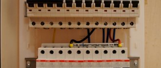
Motherboard expansion slots
(not really about cables, but useful)
8 bit slot
| Installation side | Solder side | ||||
| № | Signal | Meaning | № | Signal | Meaning |
| A1 | I/O CH CK | I/O channel monitoring | B1 | GND | Earth |
| A2 | D7 | Data line 8 | B2 | RES DRV | Reset signal |
| A3 | D6 | Data line 7 | B3 | +5V | +5V |
| A4 | D5 | Data line 6 | B4 | IRQ2 | Interrupt request 2 |
| A5 | D4 | Data line 5 | B5 | -5V | -5V |
| A6 | D3 | Data line 4 | B6 | DRQ2 | DMA request 2 |
| A7 | D2 | Data line 3 | B7 | -12V | -12V |
| A8 | D1 | Data line 2 | B8 | RES | Reserved |
| A9 | D0 | Data line 1 | B9 | +12V | +12V |
| A10 | I/O CN RDY | I/O channel readiness monitoring | B10 | GND | Earth |
| A11 | AEN | Address Enable, bus control with CPU and DMA controller | B11 | MEMW | Data is written to memory |
| A12 | A19 | Address line 20 | B12 | MEMR | Data is read from memory |
| A13 | A18 | Address line 19 | B13 | IOW | Data is written to the I/O port |
| A14 | A17 | Address line 18 | B14 | IOR | Data is read from the I/O port |
| A15 | A16 | Address line 17 | B15 | DACK3 | DMA-Acknowledge 3 |
| A16 | A15 | Address line 16 | B16 | DRQ3 | DMA 3 request |
| A17 | A14 | Address line 15 | B17 | DACK1 | DMA-Acknowledge 1 |
| A18 | A13 | Address line 14 | B18 | IRQ1 | Interrupt request 1 |
| A19 | A12 | Address line 13 | B19 | REFRESH | Memory regeneration |
| A20 | A11 | Address line 12 | B20 | CLC | System clock 4.77 MHz |
| A21 | A10 | Address line 11 | B21 | IRQ7 | Interrupt request 7 |
| A22 | A9 | Address line 10 | B22 | IRQ6 | Interrupt request 6 |
| A23 | A8 | Address line 9 | B23 | IRQ5 | Interrupt Request 5 |
| A24 | A7 | Address line 8 | B24 | IRQ4 | Interrupt request 4 |
| A25 | A6 | Address line 7 | B25 | IRQ3 | Interrupt request 3 |
| A26 | A5 | Address Line 6 | B26 | DACK2 | DMA-Acknowledge 2 |
| A27 | A4 | Address line 5 | B27 | T/C | Terminal Count, signals the end of DMA transformation |
| A28 | A3 | Address line 4 | B28 | ALE | Adress Latch Enabled, address/data uncoupling |
| A29 | A2 | Address line 3 | B29 | +5V | +5V |
| A30 | A1 | Address line 2 | B30 | O.S.C. | Clock frequency 14.31818 MHz |
| A31 | A0 | Address line 1 | B31 | GND | Earth |
16 bit slot
| Installation side | Solder side | ||||
| № | Signal | Meaning | № | Signal | Meaning |
| A1 | I/O CH CK | I/O channel monitoring | B1 | GND | Earth |
| A2 | D7 | Data line 8 | B2 | RES DRV | Reset signal |
| A3 | D6 | Data line 7 | B3 | +5V | +5V |
| A4 | D5 | Data line 6 | B4 | IRQ9 | Cascading the second interrupt controller |
| A5 | D4 | Data line 5 | B5 | -5V | -5V |
| A6 | D3 | Data line 4 | B6 | DRQ2 | DMA request 2 |
| A7 | D2 | Data line 3 | B7 | -12V | -12V |
| A8 | D1 | Data line 2 | B8 | RES | Memory communication without latency |
| A9 | D0 | Data line 1 | B9 | +12V | +12V |
| A10 | I/O CN RDY | I/O channel readiness monitoring | B10 | GND | Earth |
| A11 | AEN | Address Enable, bus control with CPU and DMA controller | B11 | SMEMW | Data is written to memory (up to 1M byte) |
| A12 | A19 | Address line 20 | B12 | SMEMR | Data is read from memory (up to 1 MB) |
| A13 | A18 | Address line 19 | B13 | IOW | Data is written to the I/O port |
| A14 | A17 | Address line 18 | B14 | IOR | Data is read from the I/O port |
| A15 | A16 | Address line 17 | B15 | DACK3 | DMA-Acknowledge 3 |
| A16 | A15 | Address line 16 | B16 | DR Q3 | DMA 3 request |
| A17 | A14 | Address line 15 | B17 | DACK1 | DMA-Acknowledge 1 |
| A18 | A13 | Address line 14 | B18 | IRQ1 | Request IRQ 1 |
| A19 | A12 | Address line 13 | B19 | REFRESH | Memory regeneration |
| A20 | A11 | Address line 12 | B20 | CLC | System clock 4.77 MHz |
| A21 | A10 | Address line 11 | B21 | IRQ7 | IRQ 7 request |
| A22 | A9 | Address line 10 | B22 | IRQ6 | IRQ 6 request |
| A23 | A8 | Address line 9 | B23 | IRQ5 | Request IRQ 5 |
| A24 | A7 | Address line 8 | B24 | IRQ4 | IRQ 4 request |
| A25 | A6 | Address line 7 | B25 | IRQ3 | IRQ 3 request |
| A26 | A5 | Address Line 6 | B26 | DACK2 | DMA-Acknowledge 2 |
| A27 | A4 | Address line 5 | B27 | T/C | Terminal Count, signals the end of DMA transformation |
| A28 | A3 | Address line 4 | B28 | ALE | Adress Latch Enabled, address/data uncoupling |
| A29 | A2 | Address line 3 | B29 | +5V | +5V |
| A30 | A1 | Address line 2 | B30 | O.S.C. | Oscillator clock 14.31818 MHz |
| A31 | A0 | Address line 1 | B31 | GND | Earth |
| C1 | SBHE | System Bus High Enabled, 16-bit data signal | D1 | MEMCS 16 | Memory Chip Select |
| C2 | LA23 | Address line 24 | D2 | I/O CS 16 | I/O card with 8 bit/16 bit carryover |
| C3 | LA22 | Address line 23 | D3 | IRQ10 | Interrupt request 10 |
| C4 | LA21 | Address line 22 | D4 | IRQ11 | Interrupt request 11 |
| C5 | LA20 | Address line 21 | D5 | IRQ12 | Interrupt request 12 |
| C6 | LA19 | Address line 20 | D6 | IRQ15 | Interrupt request 15 |
| C7 | LA18 | Address line 19 | D7 | IRQ14 | Interrupt request 14 |
| C8 | LA17 | Address line 18 | D8 | DACK0 | DMA-Acknowledge 0 |
| C9 | MEMR | Reading data from memory | D9 | DRQ0 | DMA request 0 |
| C10 | MEMW | Writing data to memory | D10 | DACK5 | DMA-Acknowledge 5 |
| C11 | SD8 | Data line 9 | D11 | DRQ5 | DMA 5 request |
| C12 | SD9 | Data line 10 | D12 | DACK6 | DMA-Acknowledge 6 |
| C13 | SD10 | Data line 11 | D13 | DRQ6 | DMA 6 request |
| C14 | SD11 | Data line 12 | D14 | DACK7 | DMA-Acknowledge 7 |
| C15 | SD12 | Data line 13 | D15 | DRQ7 | DMA 7 request |
| C16 | SD13 | Data line 14 | D16 | +5V | +5V |
| C17 | SD14 | Data line 15 | D17 | MASTER | Busmaster signal |
| C18 | SD15 | Data line 16 | D18 | GND | Earth |
Disadvantages of usb 2.0
Although the maximum data transfer rate of USB 2.0 is 480 Mbps (60 MB/s), in real life it is unrealistic to achieve such speeds (~33.5 MB/s in practice). This is due to the large delays on the USB bus between the request for data transfer and the actual start of the transfer. For example, the FireWire bus, although it has a lower peak throughput of 400 Mbps, which is 80 Mbps (10 MB/s) less than USB 2.0, actually allows for greater throughput for data exchange with hard drives and other devices. information storage devices. In this regard, various mobile drives have long been limited by the insufficient practical bandwidth of USB 2.0.
• The biggest benefit of USB 3.0 is its faster speeds (up to 5 Gbps), which are 10 times faster than older ports. • The new interface has improved energy saving. This allows the drive to go into sleep mode when not in use. • It is possible to carry out two-way data transmission at the same time. This will give higher speed if you connect several devices to one port (split the port). You can branch using a hub (a hub is a device that branches from one port into 3-6 ports). Now, if you connect the hub to a USB 3.0 port, and connect several devices (for example, flash drives) to the hub and carry out simultaneous data transfer, you will see that the speed will be much higher than it was with the USB 2.0 interface. • There is a characteristic that can be a plus and a minus. The USB 3.0 interface has increased the current to 900 mA, and USB 2.0 operates with a current of 500 mA. This will be a plus for those devices that have been adapted for USB 3.0, but a small minus is that there may be a risk when charging weaker devices, like a phone. • The physical disadvantage of the new interface is the cable size. To maintain high speed, the cable has become thicker and shorter in length (cannot be longer than 3 meters) than USB 2.0
• An important thing to note is that devices with different USB interfaces will work well and there should be no problems. But don’t think that the speed will increase if you connect USB 3.0 to an older port, or connect an older interface cable to a new port
The data transfer speed will be equal to the speed of the weakest port.