Buying expensive wired headphones does not guarantee that the wire will last for many years. Even a well-assembled headset is not reliable at the place where the wire is soldered to the drivers, control panel or connector (plug, socket). These are the weak points of any audiophile accessory that you have to repair yourself. Without knowing what the headphone pinout is, repairs are unlikely to be successful, except in cases where it is necessary to connect one or a pair of broken contacts.
The generally accepted concept of a headphone wiring diagram (pinout, wiring) is a description of the purpose of the contacts for their identification; required in case of repair and assembly of the device, presented in the form of a drawing, picture, table. Provides a description of the purpose and function of each contact.
In everyday life, the names pinout and pinout are synonyms, but in radio electronics these are words that are close in meaning, but not interchangeable. Pinout – description of the functions of the contacts (component parts of the connectors - pins). Pinout – description of the purpose of the contacts (pinout) in accordance with their numbering. Used when mounting radio elements on a printed circuit board.
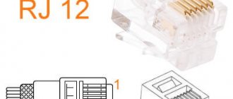
What are the types of headphone jacks?
The headphone soldering scheme depends on the plug used to connect the headset to a computer or mobile gadget. TRS connectors, also called jacks, are used as connectors. They are represented by a pointed end in the form of a cone (Tip), turning into a sleeve (Sleeve) with one or several rings in the form of cylinders (Ring) or without them. The rings are separated from each other and from the sleeve by a layer of polymer insulating material.
Depending on the dimensions of the connector, headphone connectors are divided into:
- 2.5 mm – micro-jack – with the corresponding diameter, used in mobile devices from Apple;
- 3.5 mm – mini-jack – common in computers, TVs, portable devices;
- 6.35 mm (1/4”) – jack – used in professional (studio) sound recording equipment (amplifiers, musical instruments);
- A USB interface is a rare phenomenon; such devices are preferred by eSports players due to a number of controls;
- XLR – connector for professional audio equipment;
- Lightning – equipped with Apple technology to output uncompressed audio.
In principle, thanks to the adapters, any headphones can be connected to a standard 3.5 mm jack.
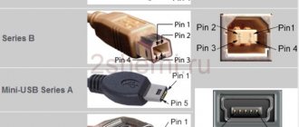
3.5 mm connectors differ in the number of contacts or pins (pin - from English pin) in the form of rings:
- two-pin or TS - two-terminal with a transition to stereo, has become obsolete;
- three-pin or TRS - common in speakers and headphones for mobile phones, players, laptops, an additional contact serves for separate transmission of audio to each ear;
- four-pin or TRRS – used in headsets, the fourth pin is needed for the microphone;
- five-pin or TRRRS - less common, mainly in noise-canceling headsets.
How to Determine Headphone Jack Size
Most users can determine the diameter of a connector or plug visually, since the vast majority of devices are equipped with a 3.5 mm jack. If the diameter of the plug in your device is smaller than usual, then it is a 2.5 mm jack; if you are using professional equipment or a musical instrument with a connector of increased diameter, it is probably a 6.35 mm connector. It will not be difficult to distinguish a jack from Lightning and US.
Inexperienced users should use a measuring device, such as a caliper, although a school ruler will show a difference of 1 mm.
How headphones work: diagram
A classic headphone wiring diagram is shown below.
The left audio channel is connected to the end (Tip), the right - to the first ring (Ring), the ground - to the sleeve (Sleeve).
High-quality models, such as Sennheiser, Sony and JBL, use a separate ground for each speaker (in the diagram this is a common contact). The wires leading to the headphones are represented by a central core, shielded with a braided cable. Depending on the circuit, the device may not work with a computer or Android smartphone (Xiaomi, Samsung).
If the central core is insulated with a varnish coating, to which silk thread fibers are sometimes added (increases resistance to stretching and fracture), low-melting solder and a special flux will be required - repairs without skills in handling a soldering iron will be difficult and not always of high quality.
How to solder a wire to different types of batteries
Despite the fact that the batteries all seem to be similar to each other, each specific case has its own soldering subtleties.
Solder it to a regular battery
How to solder a wire to a one and a half volt battery? Everything is very simple if the necessary tool is at the ready. To succeed, you need to adhere to the following sequence of actions:
- Before turning on the soldering iron, check its tip. If there is scale on it, it should be cleaned off. This can be easily done with sandpaper or a file. You need to clean until the metal sparkles.
- We connect the soldering iron to the network and place it on the stand. You need to wait a bit until it warms up. You can check the temperature by looking at the solder. If the solder responds to the touch of the tip by melting, then you can solder.
- In order to get high-quality solder, we will not wait until the soldering iron heats up, but we will go ahead and process the place on the battery where the wire will be soldered. We take a brush and process it. This is necessary so that the solder holds better, since the battery material is poorly suited for such operations. Don't forget about processing the ends of the wires. If there is no brush, any match can replace it. We just need to drop a drop of acid to carry out the treatment.
- Once you apply the acid, take a hot soldering iron and drop some solder onto the pole. We do the same with wires.
- If you use rosin, then first of all you need to tin the surface and clean the wire from varnish. But we can guarantee almost one hundred percent that the strength of soldering with rosin is much worse.
- If it was not possible to find acid, and the household only has rosin, the battery needs to be cleaned; the rosin will act as a flux. It should be applied to the surface of the element, after which we take solder with a soldering iron and tin the places where the wires will be attached. Don't forget to tin the wire too.
- If you tin it correctly, a fairly strong film will be formed on the battery, and you should solder on it.
- The wire needs to be pressed against the battery that has already been processed, then take the solder with a soldering iron and solder. We try not to move the wire so that it lies motionless in its place, then we can solder it tightly.
- After the solder has solidified, we act similarly on the other pole of the element.
The wires are now securely soldered.
How to solder a wire to the crown
What to do if you need to solder a crown element? In fact, there are no differences in the soldering process between a regular battery and a “crown”. The only difference is that the crown contacts are located on the top cover and are located next to each other. There are the following subtleties:
- Opposite contacts need to be treated with acid. The wires will be soldered at these places.
- If you use rosin, you need to tin the opposite sides of the contacts. Why is this so? This way we will avoid the possibility of a short circuit.
- The crown contacts are made very inconvenient for soldering. In their upper part they expand, and in order to tin and solder well, you need a soldering iron with a very thin tip.
The soldering process itself is very simple. You need to treat the contacts themselves, as well as the wires, with acid, after which we apply the wire to the contact. Having collected solder on the tip of the soldering iron, drop it onto the wire and smooth it out. Actually, that's all.
4.5 volt square batteries
It is very easy to solder wires to these elements. Their contacts are quite long and flexible, which makes the task of tinning them easier. And soldering is much faster and easier. The main thing is to ensure that the wires do not move during the process.
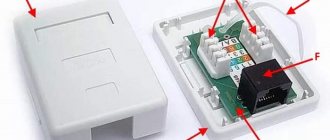
How does a headphone plug work?
If the cable is frayed, torn or the plug (pin) comes off, the device is repaired using a soldering iron with consumables and a new connector (if that is the problem).
Headphones 3.5mm
Since the 3.5 mm connectors are non-separable, for repairs you will have to buy a dismountable one, crimp the cable with a special clamp, solder the contacts according to the diagram shown below and assemble the connector.
3.5 mm plug structure
Manufacturers adhere to standards in insulation painting:
- red – left speaker – first contact or tip;
- green – right channel or ring;
- blue – speaker;
- colorless or copper-colored - mass;
- a different color – leads to the control panel (buttons).
In more expensive models, each channel may have its own mass: red-copper is the mass for the left channel, and green-copper is for the right. The microphone cable is sometimes shielded with a braided cable and varnished.
The coloring of the insulation is often violated, so relying on the coloring is wrong. To determine which pin corresponds to which channel, put on headphones and ring all combinations of wires one by one until the speaker starts to make noise. This way you can determine the mass and both channels.
The resistance between the headphones is twice as high as between ground and the audio channel.
Headphone circuit with microphone
For a headset, the schematic drawing looks different, because it is designed differently - equipped with an additional cable for transmitting sound from a microphone.
Have you noticed that in the diagrams there are different contacts for ground and microphone? Nothing strange. There are a couple of TRRS types (specifications) available with different ground and microphone contact locations. In CTIA (computer standard), the second ring (third contact) is connected to the common contact, and the sleeve is connected to the microphone, in the case of OMTP (telephone specification) it is the other way around: the 3rd contact is the speaker, the 4th is ground.
The standards are relevant only for headsets - headphones with a microphone; they have no relation to devices without one.
The standards are relevant only for headsets - headphones with a microphone; they have no relation to devices without one.
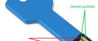
Figure No. 1
We noticed that some headsets with iPhone work adequately. The microphone fails, the volume control and track switching do not function due to the fact that most accessories are produced with the international OMPT pinout, and Apple uses the American circuit - CTIA. The problem is solved by purchasing a CTIA - OMPT adapter (see Figure No. 1) or by resoldering the 3rd and 4th contacts (they are swapped) in the headset.
The headphone pinout will allow you to correctly solder the pins when repairing the device, for example, replacing a damaged plug or cable. It depends on the number of contacts and the specification used: CTIA or OMPT.
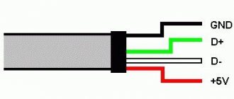
Pinout of the wire of the 3.5 connector (Jack) with and without a microphone.
Nowadays, the pinout of headphone wires with a microphone shown in the first picture below is generally used everywhere, but there is also another one, which is mainly used on old phones and in phones from some manufacturers. They differ in that the microphone and ground contacts are swapped.
If you have resoldered the headphone plug and you have a quiet sound in the headphones, and when you press the headphone call button the volume in the headphones increases, then you should resolder the ground and microphone wires (swap them).