In the modern world, the development and obsolescence of personal computer components occurs very quickly. At the same time, one of the main components of a PC - the ATX form factor power supply - has practically not changed its design over the past 15 years .
Consequently, the power supply of both an ultra-modern gaming computer and an old office PC work on the same principle and have common methods for diagnosing faults.
The material presented in this article can be applied to any personal computer power supply with a minimum of nuances.
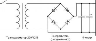
Computer power supply
The power supply is the most important and mandatory component of any system unit.
It is responsible for generating voltage, which allows you to provide power to all PC units. Also, its important function is to eliminate current leakage and parasitic currents when pairing devices. To create galvanic isolation, a transformer with a large number of windings is required. Based on this, a computer requires quite a lot of power and it is natural that such a transformer for a PC should be large and of considerable weight.
But due to the frequency of the current required to create the magnetic field, much fewer turns are required on the transformer. Thanks to this, when using a converter, small and lightweight power supplies are created.
The power supply is, at first glance, a rather complicated device, but if a minor breakdown occurs, then it is quite possible to repair it yourself.
Below is a standard power supply diagram. As you can see, there is nothing complicated, the main thing is to do everything one by one so that there is no confusion:
Schematic of a classic ATX block
Any repair of a computer power supply, as an electronic device, begins with a circuit. As you gain experience, it becomes less and less necessary, some faults can be identified by visual inspection, other problems are identified as typical - an experienced technician already knows what usually breaks down in certain power supplies. However, life sometimes throws up complex puzzles in which even an experienced master cannot do without a schematic diagram.
For a novice repairman, a circuit diagram is simply necessary. But to troubleshoot, first of all you need to disassemble the operation of a switching power supply according to its block diagram. Almost all sources are collected according to the same principle (although the circuit design of specific components may differ from manufacturer to manufacturer).
Block diagram of a computer power supply.
The mains voltage is first supplied to the filter. It does not have any effect on the operation of the source, but this node is necessary to protect the supply network from interference generated by the device itself. Next, the mains voltage is rectified and supplied to the main inverter, usually made using transistor switches. The control circuit is responsible for opening and closing the transistors. When the computer is turned off, but mains voltage is applied, it is powered by the standby voltage generating circuit. This voltage is also supplied to the computer's motherboard, powering the areas responsible for starting the PC.
The diagram does not show the protection nodes and the circuit for processing the signal from the Power_ON motherboard, which gives permission to start the inverter.
The rectified voltage of 220 volts is converted by an inverter into a pulsed voltage with a frequency of several tens of kilohertz and is supplied to the primary winding of the transformer. An EMF is induced in the secondary windings in the same way as in a conventional mains transformer. Due to the high conversion frequency, the dimensions of the transformer are compact and the device itself is lightweight.
The voltages of the secondary windings are rectified and filtered. Feedback circuits are used to stabilize the output voltage and limit the current.
Where is the power supply located in the system unit and how to disassemble it
To gain access to the computer's power supply, you must first remove the left side wall from the system unit by unscrewing two screws on the rear wall on the side where the connectors are located.
To remove the power supply from the system unit case, you need to unscrew the four screws marked in the photo. To conduct an external inspection of the power supply, it is enough to disconnect from the computer units only those wires that interfere with the installation of the power supply on the edge of the system unit case.
Having placed the power supply on the corner of the system unit, you need to unscrew the four screws located on top, in the pink photo. Often one or two screws are hidden under a sticker, and to find the screw you need to peel it off or pierce it with the tip of a screwdriver. There are also stickers on the sides that make it difficult to remove the cover; they need to be cut along the line of mating parts of the power supply housing.
After the cover from the power supply unit is removed, be sure to remove all dust with a vacuum cleaner. It is one of the main reasons for the failure of radio components, since by covering them with a thick layer, it reduces the heat transfer from the parts, they overheat and, working in difficult conditions, fail faster.
For reliable operation of the computer, it is necessary to remove dust from the system unit and power supply, and also check the operation of coolers at least once a year.
Power Device Diagnostics
Before you proceed directly to diagnosing a computer power supply, you need to make sure that the problem lies with it. The easiest way to do this is by connecting a known-good unit to the system unit. Troubleshooting in the computer power supply can be done using the following method:
- If the power supply is damaged, you should try to find a manual for its repair, a circuit diagram, and data on typical faults.
- Analyze the conditions under which the power source worked, whether the electrical network is working properly.
- Using your senses, determine whether there is a smell of burning parts and elements, whether there was a spark or flash, listen to whether you can hear any extraneous sounds.
- Assume one fault and highlight the faulty element. This is usually the most time-consuming and painstaking process. This process is even more labor-intensive if there is no electrical circuit, which is simply necessary when searching for “floating” faults. Using measuring instruments, trace the path of the fault signal to the element on which there is a working signal. As a result, we can conclude that the signal disappears on the previous element, which is non-working and requires replacement.
- After repair, it is necessary to test the power supply with its maximum possible load.
Monitoring peripheral power connectors
If you need to check individual connectors, continue testing the power supply. Verification algorithm:
- Turn off the switch on the power supply panel and unplug it from the outlet.
- Connect the tester socket connector to the corresponding SATA connector with a 15-pin Molex modification. Do not connect more than one of these peripheral connectors at the same time, otherwise the tester may be damaged.
- Two connectors on the motherboard must remain connected for these tests with other connectors.
- Connect the source, and then turn on the button on the panel.
- The LEDs labeled +12V, +3.3V, and +5V correspond to the voltage supplied through the connected peripheral power connector and should be lit as expected. Otherwise, the power supply needs to be replaced.
- The SATA connector provides +3.3 VDC. You can see the voltage supplied by different connectors by looking at the ATX connector output pin charts.
- Repeat this process for the other power connectors one at a time, except for the connector on the motherboard, which remain connected to the tester at all times.
- After completing the tests, turn off the power supply, disconnect the tester cables, and then connect the internal devices of the PC to the source.
- After the power supply has been tested or replaced with a new one, you can turn on the PC again.
Necessary tools for repair
In order to begin repairing the power supply yourself, you should have the necessary tools on hand.
First you need to arm yourself with computer diagnostic tools:
- working power supply unit;
- post card;
- The memory stick is in working condition;
- compatible video card;
- CPU;
- multimeter;
To perform the repair itself you will also need:
- soldering iron and everything for soldering;
- screwdrivers;
- the computer is in working order;
- oscilloscope;
- tweezers;
- insulating tape;
- pliers;
- knife;
Naturally, this is not so much for a complete renovation, but this is enough for home renovation.
Checking a repaired power supply
After the ATX unit has been repaired, it is important to properly turn it on for the first time. At the same time, if not all problems have been resolved, the repaired and new components of the device may fail.
The power supply can be started autonomously, without using a computer unit. To do this, the PS_ON contact is bridged with the common wire. Before switching on, a 60 W light bulb is soldered in place of the fuse, and the fuse is removed. If the light bulb starts to shine brightly when turned on, then there is a short circuit in the unit. If the lamp flashes and goes out, the lamp can be unsoldered and a fuse installed.
The next stage of checking the power supply occurs under load. First, the presence of standby voltage is checked; for this, the output is loaded with a load of about two amperes. If the duty station is in order, the power supply is turned on by closing PS_ON, after which measurements of the output signal levels are made. If you have an oscilloscope, you can see the ripple.
Signs of a broken power supply
In a vacuum, a power supply failure will not occur. If signs appear that indicate its malfunction, then before starting repairs, the reasons that led to its failure must first be eliminated.
Causes:
- Poor quality of supply voltage (voltage drops).
- Not very high quality components.
- Defects that were made at the factory.
- Poor installation.
- The arrangement of parts on the power supply plate is arranged in such a way that it leads to contamination and overheating.
Signs:
- The computer may not turn on, and if you open the system unit, you may find that the motherboard is not working.
- The power supply may work, but the operating system will not start.
- When you turn on the PC, everything seems to start working, but after a while everything turns off. This may trigger the power supply protection.
- The appearance of an unpleasant odor.
A faulty power supply cannot be missed, since problems begin with turning on the system unit (it does not turn on at all) or it turns off after several minutes of operation.
If at least one of the problems is noticed, you should think about eliminating the malfunction, otherwise, the computer may completely fail, and then you cannot do without the intervention of an experienced specialist.
Main problems:
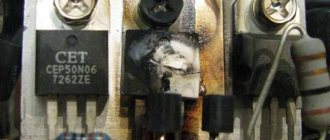
- The most common issue that can affect the operation of the power supply is a swollen capacitor. Such a problem can only be determined after opening the power supply unit and fully inspecting the capacitor.
- If at least 1 diode fails, then the entire diode bridge fails.
- Burning resistors that are located near capacitors and transistors. If such a problem occurs, then you will need to look for the problem in the entire electrical circuit.
- Problems with the PWM controller. It is quite difficult to check; for this you need to use an oscilloscope.
- Power transistors also often fail. A multimeter is used to check them.
Note! Power capacitors tend to hold a charge for some time; therefore, it is not recommended to touch them with bare hands after the power is turned off. Also, you should remember that when the power supply is connected to the network, you do not need to touch the stove or radiator.
Block diagram of the power supply unit of an ATX computer
A computer power supply is a rather complex electronic device and repairing it requires deep knowledge of radio engineering and the availability of expensive equipment, but, nevertheless, 80% of failures can be eliminated independently, having the skills of soldering, working with a screwdriver and knowing the block diagram of the power source.
Almost all computer power supplies are made according to the block diagram below. I have shown the electronic components in the diagram only those that most often fail and are available for non-professionals to replace on their own. When repairing an ATX power supply, you will definitely need color coding of the wires coming out of it.
The supply voltage is supplied via a power cord through a plug-in connection to the power supply board. The first element of protection is fuse Pr1, usually rated at 5 A. But depending on the power of the source, it may have a different rating. Capacitors C1-C4 and inductor L1 form a filter that serves to suppress common-mode and differential noise that arises from the operation of the power supply itself and can come from the network.
Surge filters assembled according to this scheme are required to be installed in all products in which the power supply is made without a power transformer, in televisions, VCRs, printers, scanners, etc. Maximum efficiency of the filter is possible only when connected to a network with a ground wire. Unfortunately, cheap Chinese computer power supplies often do not have filter elements.
Here is an example of this: the capacitors are not installed, and instead of the inductor, jumpers are soldered. If you are repairing a power supply and find that filter elements are missing, it is advisable to install them.
Here is a photo of a high-quality computer power supply, as you can see, filter capacitors and a noise suppression choke are installed on the board.
To protect the power supply circuit from supply voltage surges, expensive models install varistors (Z1-Z3), pictured on the right side in blue. Their operating principle is simple. At normal network voltage, the resistance of the varistor is very high and does not affect the operation of the circuit. If the voltage in the network increases above the permissible level, the resistance of the varistor sharply decreases, which leads to the fuse blowing, and not to the failure of expensive electronics.
To repair a failed unit due to overvoltage, it will be enough to simply replace the varistor and fuse. If you don’t have a varistor at hand, then you can only get by by replacing the fuse; the computer will work normally. But at the first opportunity, in order not to take risks, you need to install a varistor in the board.
Some models of power supplies provide the ability to switch to operate at a supply voltage of 115 V; in this case, the contacts of switch SW1 must be closed.
For a smooth charge of electrolytic capacitors C5-C6, connected immediately after the rectifier bridge VD1-VD4, an RT thermistor with a negative TCR is sometimes installed. In a cold state, the resistance of the thermistor is a few ohms; when current passes through it, the thermistor heats up and its resistance decreases by 20-50 times.
To be able to turn on the computer remotely, the power supply has an independent, additional low-power power source that is always on, even if the computer is turned off, but the electrical plug is not removed from the socket. It generates a voltage of +5 B_SB and is built according to the circuit of a transformer self-oscillating blocking oscillator on a single transistor, powered from a rectified voltage by diodes VD1-VD4. This is one of the most unreliable components of the power supply and is difficult to repair.
The voltages required for the operation of the motherboard and other devices of the system unit, when leaving the voltage generation unit, are filtered from interference by chokes and electrolytic capacitors and then supplied to consumption sources through wires with connectors. The cooler, which cools the power supply itself, is powered, in older power supply models from a voltage of minus 12 V, in modern ones from a voltage of +12 V.
Possible PSU malfunctions and ways to eliminate them
To troubleshoot a computer power supply, you need a certain set of instruments. It is not always possible to determine the problem by external signs. At a minimum, a multimeter is required. Having an oscilloscope is highly recommended.
We recommend reading: Types of resistors, what they are needed for, how to check, designation, connection
Before you start diagnosing the power supply, you need to finally make sure that the problem is there. To do this, you need to remove the largest connector from the motherboard (20 or 24 contacts), close the black and green wires on it with a wire jumper (paper clip), simulating the start signal from the motherboard. If the power supply starts up (you can hear it from the hum of the fan), you just need to measure all output voltages. If they are ok, then the reason is not the power supply. If something goes wrong and the source does not start, it means that the power supply is not working.
Fuse blown
Most often, a fuse in a glass case is installed in the power supply. It is usually located in a horizontal position and is located next to the surge protector. Sometimes the fuse is installed vertically and has heat shrink on it. On the board it is designated as F1.
To check the fuse, you need to test it with a multimeter. In this case, it needs to be replaced. If you don’t have a fuse with leads on hand, you can solder them to a regular one. To do this, solder two wires to the cups at both ends of the latter.
Varistor
Varistors are designed to protect the power supply from surge voltages. As the voltage increases, its resistance decreases sharply, and thus it absorbs excess energy. This increases the current, which can cause the fuse to blow.
If the voltage surge is too large or prolonged, the varistor may burn out. In this case, it turns black and splits. After replacing it, it is recommended to check other parts included in the secondary circuit.
Checking the rectifier
An assembly of 4 diodes or a diode bridge can be used as a rectifier in the power supply.
The test can be performed without desoldering parts from the board. In the forward direction, the resistance should be small, and in the opposite direction it should increase sharply.
The diode bridge continuity diagram is shown in the figure below. First, we install the negative probe of the multimeter on the terminal marked with the “+” sign and use the positive probe to check the resistance. In the directions marked by arrows, it should be small, and in the opposite directions it should show infinity (break). We do the same for the remaining legs.
If one of the diodes or the diode bridge is broken, then you also need to check the capacitors installed in the input filter and the key transistors. Since the alternating voltage that appeared after the breakdown could damage these parts.
Power supply standby voltage
Next you need to check the presence of standby voltage. It serves to power the section of the motherboard circuit responsible for the computer startup algorithm. Another purpose of the StandBy power supply is to power the power supply pulse generator circuit. You need to check it on pin 9 of the motherboard connector (ATX24 or ATX20). There should be about 5 volts.
ATX24 connector pinout.
You also need to check the presence of supply voltage (about 12 volts) on the pulse generation circuit. If it is made on a TL494 chip (a very common case), then you can measure the voltage at pin 12.
Power output for TL494.
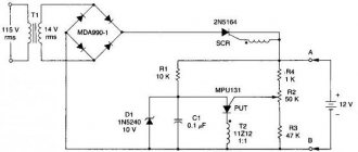
If problems are found, then you cannot do without a power supply circuit diagram. The standby voltage is generated in most cases using an additional converter, but it can be made according to a variety of schemes. As an example, the section that forms the Stand By power supply is given.
Emergency power supply scheme.
The generator is made on a transistor. The generator winding is included in the feedback circuit. The pulses are transformed into secondary windings and rectified. The microcircuit is powered by an unstabilized voltage, while the motherboard is supplied with voltage stabilized by a linear regulator. The most likely reason for the non-working state of such a generator is the failure of one of the semiconductor devices (transistors, diodes). The problem can be detected by measuring the modes of semiconductors, and if questionable voltage values are detected at the terminals, by unsoldering and testing a specific element.
Oxide capacitors
Oxide capacitors most often fail due to overheating. This may be due to poorly organized heat removal from the internal space of the power supply unit. But most often, overheating occurs due to the fact that the manufacturer, out of savings, chose oxide capacitors without a sufficient voltage reserve.
As a result, even with minor surges or when emissions appear, the electrolyte inside the container heats up and gradually evaporates through leaks in the housing. When the liquid level drops below a certain value, the electrolyte begins to boil and the capacitor body swells. This can be detected visually.
Swollen capacitors.
Even if such a capacitor is still alive, it must be changed immediately - its hours are numbered. Replacement is carried out with capacitors of the same capacity and the same voltage, but if the dimensions on the board allow, it is better to install elements with a higher voltage (excess capacity also does not hurt).
If the manufacturer has used low-quality capacitors, then during operation the electrolyte simply flows out of them. Traces of corrosion remain on the surface. These items must also be replaced immediately.
Chokes
Often the power supply does not work because the inductor winding burns out due to improper operation of the cooler. Their failure can be determined by carbon deposits on the varnish. You can unsolder them and buy new ones or rewind them altogether.
Transformer
There is only one way to check a transformer - by testing the terminals. If there is no contact, it needs to be replaced. Other faults are unlikely to be fixed on your own.
By the way, if the startup of the power supply was previously accompanied by a strong burning smell, then the problem is in the transformer. But they rarely fail.
PWM
The problem with PWM controllers is that they are difficult to diagnose without an oscilloscope. We need a complete picture of pulse modulation.
All that remains is to measure the standby power supply from the PWM controller. You will need to find out the name (for example, SG6105, 1200p60) and find it by the Datasheet number. There will be a diagram of all the legs and it looks like this:
Next, the negative probe of the multimeter must be lowered to the ground, and the positive probe must be passed along the following contacts: V3.3; V5; V12; ORR. If in resistance measurement mode it is too low, it needs to be replaced.
If there are cracks on it or it gets very hot, repairing switching power supplies with your own hands comes down to a simple replacement without dialing.
Diodes
You just need to call. If the multimeter shows a break in both directions, they need to be replaced.
Simplified ATX Test Method
If the ATX power supply does not start, check that it is operating correctly and that its voltages comply with the manufacturer's specifications. To perform these tests, use a screwdriver to open the box and a cable to bypass the power. In this case, use a simple paperclip and one multimeter to perform the necessary measurements. First of all, you need to take certain precautions before opening the PSU case. The source must be unplugged and the power button on the rear panel must be in the off position.
First you need to open the box with a screwdriver and find the power supply connector, consisting of 24 (20 + 4) contacts. Once found, disconnect it from the motherboard. The next step is to find a green wire called PS_ON (PowerSupply ON), which is connected to the common black cable of the PSU. Using a jumper with a clamp, the green wire is connected to any black wire of the connector, after which the source will be artificially turned on without the need to connect the base board. After this, connect the power cable to the mains and press the button on the rear panel to turn it on. In order to make sure that the bridge is made correctly, turn on the power source, and if the fan rotates and drives air, then everything is done correctly.
Now you need to take measurements, for which you use a multimeter. Red and black connectors are located in the tension measurement position: black connector for COM and red for V Hz.
The rotary switch is located in the DC voltage measurement area at position 20 as it will measure voltages of 3.3V, 5V and 12V.
Other problems
Another cause of power supply malfunction may be a malfunction of powerful transistors in the inverter switches. If pulses arrive at the bases (gates) of the triodes, but there are none in the collector (drain) circuit, the transistors must be unsoldered and ringed. Bipolar triodes are connected like two diodes with a common terminal.
We recommend reading: How to measure resistance with a multimeter: instructions, photos, videos
Testing bipolar triodes.
To test MOSFETs, it is better to assemble a simple circuit.
Field-effect transistor testing circuit.
You also need to check for the presence of the Power_good signal on pin 8 of the motherboard connector. It may turn out that all the voltages are in order, but the circuit for generating this signal is faulty. The computer will perceive this as a fault in the power supply.
Revision using the advanced tester
The following instructions only apply to the dedicated ATX Coolmax PS-228 power supply tester, or any other similar tester with an LCD screen.
Important: This process is considered complex, the user needs to carefully follow the instructions below.
Time required: Testing a PSU with a PSU test device usually takes about 30 minutes, or a little more for beginners.
Algorithm of actions:
- Learn important safety tips when repairing your PC. Testing a power supply involves working with high voltage electricity, a potentially hazardous activity. Safety should be the main concern during a block inspection.
- Open the case by first turning off the computer, disconnecting the power cord and everything connected to the outside of the computer.
- Move the disconnected unit to a place where you can easily work, such as a desk. The user will not need a keyboard, mouse, monitor or other external peripheral devices.
- Disconnect the power connectors of each internal unit on the side panel. An easy way to ensure that each power connector is unplugged is to remove the power cord kit that comes from the PSU. Each group of cables must end with one or more power connectors. There is no need to disconnect data cables or other cables that are not connected to the power supply.
- Group all power cables and connectors for easy testing. When organizing power cables, it is recommended to disconnect them and remove them from the computer case as far as possible. This will make connecting the power connectors to the extended tester as easy as possible.
- Make sure the power supply voltage switch located on the rear panel is correctly set for your country of residence. In the US this switch should be set to 110V/115V, and in Russia to 220/230.
- Connect the 24-pin ATX power connector and the 4-pin ATX power connector on the motherboard in the PC power supply tester. Depending on the source, there may not be a 4-pin motherboard connector, but there may be 6 or 8 pins. If there is more than one type, simply connect one at a time along with the 24-pin main power connector.
- Connect the power supply to an electrical outlet and turn on the switch. Some units do not have a switch on the rear panel. If the source being tested does not work, simply connect the device to supply power. Press and hold the on/off button of the tester for PC power supplies. The user should hear the fan inside the source start to operate.
Some versions of the improved Coolmax PS-228 power supply tester do not require constantly pressing the power button. Just because the fan is running doesn't mean the power supply is properly supplying power to the rest of your devices. If the power supply fan does not start during testing, even if the source is in good condition, it may be burnt out and should be checked separately.
The Advanced Source Tester's LCD display should be turned on and the user will see test numbers for all metrics. If the voltage shows "LL" or "HH" or if the LCD does not light up, the PSU is not working and will need to be replaced.
How to repair a switching power supply with your own hands: important tips for beginners
A professional electrician always begins work by preparing the workplace, tools and assessing the risks that need to be prevented.
You should be well aware that repairing a switching power supply with your own hands means working under voltage in live circuits.
Preparatory work: where to find a switching power supply circuit and what measuring instruments are needed
Now manufacturers of electrical equipment keep their professional secrets secret: the UPS diagram is not publicly available. We are going to do the repairs with our own hands, and not in a specialized service center.
We proceed as follows:
- We open the case and inspect the electronic board.
- We find a powerful transistor (output switch) and a microcircuit (PWM controller). Sometimes they can be united by a common building.
- We write down the markings and use them to look for a complete description (data sheet) in reference books or via the Internet.
- Based on the documentation found, we study the pinouts of the microcircuit, how to connect it, and compare the information obtained with the real design.
On small-sized microcircuits, full markings do not always fit. Then manufacturers make a code designation of several letters and numbers. It is more difficult to search for information on it, you will have to work harder.
It is unlikely that it will be possible to repair the UPS without an electrical measuring tool. You can get by with old pointer instruments - testers, like my Ts4324.
They allow you to measure most electrical parameters with an accuracy class sufficient for repair, but require increased attention and additional calculations.
Nowadays it is much more convenient to use a digital multimeter for measurements.
I explained all the rules for handling it for beginners in great detail in a specially published article. I hope you find it useful.
An oscilloscope will be of great help in troubleshooting. It allows you to view voltage oscillograms of almost every UPS node.
Based on their type and size, it is quite easy to assess the performance of each electronic element in the circuit. Any model is suitable for taking measurements: old analog or modern digital.
But if you don’t have an oscilloscope, then don’t despair. In the vast majority of cases, you can get by with a digital multimeter or pointer tester.
Algorithm for repairing a switching power supply: complete instructions in 7 consecutive steps
Faults inside the UPS can be divided into two categories:
- Obvious burnout with charring of parts, tracks, explosions of capacitors.
- Silent loss of performance without manifestation of external damage.
The algorithm for repairing a switching power supply consists of two successive stages: first, primary checks are carried out without applying voltage, and then the electrical characteristics are measured.
The first stage of repair requires that steps No. 1 and 2 be performed only with the power turned off.
Step No. 1: external and internal inspection
Initially, you will have to open the case and carefully examine its contents. Anything that is in doubt must be thoroughly checked.
The first type of damage is fraught with the danger that it can be difficult, if not impossible, to determine the markings of burnt parts. At this stage, repairs may stop.
Step #2: Checking the Input Voltage
In the second case, the search for the location of the defect begins with checking the presence of 220 volt power circuits. Often the power cord is damaged or the fuse is blown.
The fuse link usually burns out due to a breakdown of the semiconductor junction of the rectifier bridge diodes, transistor switches, or defects in the unit that controls the standby mode.
All this needs to be checked with a multimeter: it is switched to ohmmeter mode and the state of the electrical resistance of the indicated circuits is measured, looking for a break that needs to be eliminated.
I’ll say right away that you shouldn’t calm down if you find a blown fuse: it doesn’t just fail. There is clearly a short circuit or overload in the UPS circuit: you will have to look for additional damaged parts.
If there is no damage, then the switching power supply is placed on the dielectric base of the table and 220 volts are supplied to it.
The input voltage must be checked with a multimeter in voltmeter mode, measurements must be taken at the input of the surge protector and after the fuse link.
Step No. 3: checking the condition of the surge protector and rectifier
The performance of this circuit should be determined with a voltmeter in the AC voltage measurement mode. Pay attention to the magnitude of its signal at the input and output. For a working device, the amplitude of the harmonics should be practically the same.
The quality of filtering of extraneous interference is well shown by an oscilloscope, but if it is missing, then it is not so bad. Its measurements may be needed in exceptional cases; it is permissible to skip them.
The operation of the rectifier is also checked: the voltmeter is switched to DC circuit mode to measure the output voltage. Its ends are installed on the legs of the electrolytic capacitor or their tracks.
When the voltage at the output of the filter or rectifier is not within the normal range, you will have to check the serviceability of all the parts that are included in its circuit.
First of all, pay attention to electrolytic capacitors, which dry out when overheated, losing capacity, or even explode. Immediately evaluate the correctness of their geometric shape.
Any slight distortion, especially a swollen capacitor, is a sign of internal damage. If the geometry is not broken, then proceed to electrical measurements.
This can be done using a pointer tester in two ways:
- The capacitor is being discharged. The device is switched to ohmmeter mode and the capacitance is charged from its internal source: simply place the probes on the legs and hold for a short time.
Then the tank is switched to voltmeter mode and the discharge of the capacitance is observed. The method is approximate, estimated, but quite fast.
- A more accurate, but more difficult, way to evaluate a capacitor is by measuring its capacitance. A sinusoidal current is passed through it, and its magnitude and voltage drop are assessed by measurements. Using Ohm's law, the capacitive reactance Xc is calculated. The capacitance of the capacitor C is calculated from it.
A digital multimeter allows you to simply determine the capacitance value using a regular measurement. It already has a built-in generator inside, and the processes of measuring current and voltage, as well as calculations, are automated.
Secondly, analyze the serviceability of the diodes. All of them, including power ones, must conduct current only in one direction. Their performance is assessed with a multimeter in ohmmeter or continuity mode.
Step No. 4: checking the inverter operation
We take into account that the construction circuit of each high-frequency generator is assembled not only from various parts, but also with a wide variety of design solutions.
We recommend reading: Temperature sensor: types, purpose, device, typical circuits
Often the generator is combined on an electronic board with a high-frequency transformer, as well as an output rectifier and filter. We will proceed from the fact that we do not have an exact scheme for constructing a UPS: we check it by external, indirect signs.
We work with a multimeter in voltmeter mode: we consistently evaluate the voltage amplitudes at different points of the inverter circuit. We take into account that the device shows effective values, and not maximum, amplitude values.
An oscilloscope with a voltage divider is more appropriate here: it will also show the shape of each signal, which can greatly facilitate troubleshooting.
Step #5: Checking Output Voltages
Please note that many UPSs, especially computer ones, have several output circuits that differ in voltage, for example, 12, 5 and 3.3 volts. Moreover, they can be assembled for different loads.
They all need to be checked with electrical measurements. To start the computer unit into operation, you need to short-circuit the control signal to start the power supply unit PS_On to the black neutral wire.
Applying power to a computer UPS in idle mode is harmful to the electronic circuit. The resource of its work is reduced.
To test under voltage, it is recommended to assemble a simple circuit using ordinary resistors. It is advisable to choose them with high power and place them on radiators or provide forced airflow during the test.
If you use computer working units as a load, for example a CD drive, HDD or motherboard, as some technicians sometimes recommend, then there is a high probability that an unresolved power supply fault will damage them too.
Step No. 6: checking the operation of overload protection
The operation is carried out after checking the quality of the output voltages in all sections of the circuit.
Switching power supplies for complex electronic devices (monitors, digital TVs and similar equipment) include current protection. It removes power from the connected circuit when dangerous currents occur in it in excess of the rated value.
This protection operates from a built-in current sensor, from which an overload signal is sent to the control chip. It, in turn, turns off the power to the output power contact from the created emergency mode.
Step #7: checking the output voltage stabilization circuit
At this final stage, the operation of the inverter control unit with a changing input supply voltage is assessed by the action of the feedback circuit.
The verification algorithm consists of the following stages:
- The UPS is disconnected from the 220 volt input voltage circuits.
- A dial tester switched to ohmmeter mode is connected to the output of the optocoupler, although a digital multimeter can also be used.
- A constant voltage from an adjustable source is supplied to the output of the +/-12 V power supply, its value is changed and the operation of the optocoupler is controlled using the ohmmeter readings.
At a reduced voltage, the optocoupler will have a high electrical resistance, and when the circuit reaches 12 volts, its output will open and the ohmmeter needle will sharply reduce its readings.
Such operation indicates the joint serviceability of the zener diode, optocoupler and stabilization circuit.
It also wouldn’t hurt to separately check the integrity of the power transistor. But first it must be unsoldered from the board.
If the dimensions of the block allow, it can be modified by replacing:
- high power rectifier diodes;
- storage capacitors of higher capacity and voltage.
We measure voltages
If everything is OK, we turn on our power supply to the network using the network cable that comes with the power supply, and do not forget about the power button if you had it off.
Next, measure the voltage on the purple wire
My patient showed 0 volts on the purple wire. I take a multimeter and connect the purple wire to ground. Ground is black wires with the inscription COM. COM is short for “common,” which means “general.” There are also some types of "lands":
As soon as I touched the ground and the purple wire, my multimeter made a meticulous “ppiiiiiiiiiiiiiiiiiiiiiiiiiiiiiiight” sound and showed zeros on the display. Short circuit, definitely.
Well, let's look for a circuit for this power supply. After googling the Internet, I found a diagram. But I found it only on Power Man 300 Watt. They will still be similar. The only differences in the circuit were the serial numbers of the radio components on the board. If you know how to analyze a printed circuit board for compliance with the circuit, then this will not be a big problem.
And here is the circuit for Power Man 300W. Click on it to enlarge to full size.
Checking voltage after repair
After repair, you need to check the presence of output voltages. To do this, you need to install a jumper between the black and green conductors on the ATX connector and connect load equivalents to the output connectors - without them, the output voltages may be higher than the rated ones. It is better to do this before applying mains voltage, because some circuits simply will not start without a load.
You can use resistors or 12-volt automotive incandescent lamps as ballast. The load must provide an output current within 10..90% of the nominal.
For clarity, we recommend a series of thematic videos.
Repairing a computer power supply is not difficult if you have the equipment and sufficient qualifications. But repairing a computer's power supply with your own hands is considered impractical, since troubleshooting takes a lot of time. There is an opinion that it is easier to buy a new unit, because by the time the power supply fails, the computer is either upgraded or requires an upgrade in the near future. Therefore, a new power supply with increased power is needed. There is a fair amount of truth in this approach, but sometimes repairs are required. Also, a refurbished power supply can be converted into a laboratory power supply or a charger. The review materials will be useful in this case.
How can I check the UPS?
If in doubt, you can check the operation of the UPS. To do this, it must be turned on under load - some sources simply do not start at idle. As an equivalent, you can use car light bulbs if the unit is designed for an output voltage of 12 volts, or other incandescent light bulbs, connecting them in series and parallel to create the required load. If there are no suitable lamps, you can make up a load of resistors of the required resistance and required power.
A light bulb as a power supply load.
For a simple check of functionality, the current through the lamps must be at least 5..10% of the UPS rating. If the source is with forced cooling, you need to load it so that the current is at least half of the maximum allowable (or better, closer to the upper limit). This is necessary to force the temperature relay to operate to check that the fan is turned on.
Functionality check
After the reasons that brought the power supply out of operating mode have been eliminated, it must be checked.
The most basic operation is to turn on the computer to the network. But, by the way, this can be done without connecting a PC. It is enough to connect any load to the power supply, for example a CD-ROM, after which you need to short-circuit the green and black wires in the power supply connector and turn it on.
If everything is in order, then the fan and drive LED will immediately turn on on a working power supply. And naturally, the reverse reaction of the power supply (if nothing starts working), then the cause is not eliminated.
Once the serviceability of the device is confirmed, you can begin assembling the system unit.
Pinout of the main PSU connector
To carry out repairs, we will also need to know the pinout of the main power connector, it is shown below.
PSU plugs: A – old style (20pin), B – new (24pin)
To start the power supply, you need to connect the green wire (PS_ON#) to any black zero wire. This can be done using a regular jumper. Note that some devices may have color markings that differ from the standard ones; as a rule, unknown manufacturers from the Middle Kingdom are guilty of this.
Tips and tricks for repairs
Before you undertake independent repair of the power supply, you need to be fairly confident in your knowledge of electrical appliances:
- To begin with, you can read the literature, which can easily be found on the Internet, which describes in detail the causes and symptoms of power supply failure.
- We need to study the diagram.
- Before you begin disassembling the system unit, make sure it is unplugged from the network. It will be better if it is completely cooled.
- Dust and any dirt should be blown out using a vacuum cleaner or hair dryer. It is not recommended to use a damp cloth.
- The study should be carried out one by one of all details. It is advisable to check the operation of the power supply every time.
- If you don’t have the skills to work with a soldering iron , and you can’t do without soldering, it’s better to contact a specialist, it will cost less.
- If spare parts and repairs are more expensive than a new power supply unit, then it is better to think about purchasing a new part.
- Before you begin repairing the power supply, you need to make sure that the power cable and switch are in good working order.