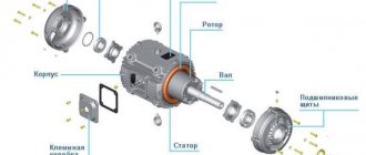
Electric motor power calculation
Calculation of electric motor power by current can be done using our online calculator:
The result obtained can be rounded to the nearest standard power value.
Standard values of electric motor power : 0.25; 0.37; 0.55; 0.75; 1.1; 1.5; 2.2; 3.0; 4.0; 5.5; 7.5; eleven; 15; 18.5; 22; thirty; 37; 45; 55; 75 kW, etc.
Engine power is calculated using the following formula:
P=√3UIcosφη
- U - Rated voltage (voltage to which the electric motor is connected);
- I - Rated current of the electric motor (taken from the passport data of the electric motor , and in their absence is determined by calculation);
- cosφ - Power factor - the ratio of active power to total power (taken from 0.75 to 0.9 depending on the power of the electric motor);
- η - Efficiency factor - the ratio of the electrical power consumed by the electric motor from the network to the mechanical power on the motor shaft (taken from 0.7 to 0.85 depending on the power of the electric motor);
How to determine the power of an electric motor
The easiest way is to look at the plate and find the value in kilowatts. For example, in the picture it is 45 kW.
Please note that this value on the plate indicates the active power consumed from the electrical network.
The total power will be equal to the sum of active and reactive power. Electric meters in a house or garage count only the consumption of active electricity, and reactive energy is recorded only in enterprises using special meters. The higher the cos(fi) of an electric motor, the lower the reactive energy component of total power will be. Do not confuse cos(fi) with efficiency. This indicator shows how much electricity is converted into useful mechanical work, and how much into useless heat. For example, an efficiency of 90 percent means that a tenth of the electricity consumed is spent on heat losses and friction in the bearings. You should keep in mind that the passport or plate indicates the rated power, which will be equal to this value only if the optimal load on the shaft is achieved. However, you should not overload the shaft for a number of reasons; it is better to choose a more powerful motor. At idle, the current will be much lower than the nominal value.
How to determine the rated power of an electric motor? On the Internet you will find many different formulas and calculations. For some, you need to measure the dimensions of the stator, for other formulas you will need to know the current value, efficiency and cos(fi). My advice is don't bother with all this. Practical measurements will still be better than these calculations. And you won’t need anything at all to carry them out.
How to determine the power of any electrical appliance in the house or garage? Of course, using an electricity meter. Before starting the measurement, unplug all electrical appliances from the sockets, lighting and everything connected to the electrical panel.
Next, if you have an electronic meter of the Mercury type, everything is very simple: you just need to turn on the motor under load and drive for about 5 minutes. The electronic display should display the load value in kW currently connected to the meter.
Motor current calculation
The rated and starting current of an electric motor can be calculated by power using our online calculator:
The rated motor current is calculated using the following formula:
Inom=P/√3Ucosφη
- P - Rated power of the electric motor (taken from the motor’s passport data or determined by calculation);
- U - Rated voltage (voltage to which the electric motor is connected);
- cosφ - Power factor - the ratio of active power to total power (taken from 0.75 to 0.9 depending on the power of the electric motor);
- η - Efficiency factor - the ratio of the electrical power consumed by the electric motor from the network to the mechanical power on the motor shaft (taken from 0.7 to 0.85 depending on the power of the electric motor);
The starting current of the electric motor is calculated using the formula:
Istart=Inom* K
- K - Starting current multiplicity, this value is taken from the electric motor passport, or from catalog data (in the above online calculators, the starting current multiplicity is determined approximately based on the other specified characteristics of the electric motor).
What is the rated current of an electric motor
Calculation of electric motor current
Calculation of the rated current of a three-phase asynchronous electric motor
To correctly select the electrification system for a lifting and transport mechanism, be it a trolley busbar or cable supply, you need to know the rated current of the electrical installation.
Below is the calculation form for a three-phase AC induction motor:
In=Pn/√3*Un*cosφн*ηн or Pн/1.73*Un*cosφн*ηн,
where Рн is the rated power of the electric motor (W),
Un — rated voltage of the electric motor (V),
ηн - nominal efficiency of the engine,
cos φн is the rated power factor of the motor.
The rated data of the electric motor are indicated on the nameplate or in other technical documentation attached to the electric motor.
For convenience, here is an example of a calculation:
It is necessary to determine the rated current of a three-phase asynchronous AC electric motor if Рн = 25 kW, rated voltage Un = 380 V, rated efficiency ηн = 0.9, rated power factor cos φн = 0.8.
The rated voltage of the three-phase network is 380 V - the motor windings are connected in a star configuration. The rated voltage of a three-phase network is 220 V - the connection of the motor windings is in a delta pattern.
We convert the rated power from kW to Watts: Pn = 25 kW = 1000*25 = 25000 W
Next: In = 25000/√3*380 * 0.8 * 0.9 = 25000/1.73*380*0.8*0.9 = 52.8 A.
Share link:
- Click to share on Twitter (Opens in new window)
- Click here to share content on Facebook. (Opens in a new window)
- We recommend
- Comments
IP65 degree of tightness of equipment
IP rating (Ingress Protection Rating, input protection) is a system for classifying the degree of protection of the electrical equipment shell from the penetration of solid objects and water in accordance with the international standard IEC 60529 (DIN 40050, GOST 14254-96). For example, the radio control for the F21-E1B crane has a sealing class of IP-65. The first digit means
COPPER and COPPER ROLLED
Copper grades and their chemical composition are defined in GOST 859-2001. Brief information about copper grades is given below (the minimum copper content and the maximum content of only two impurities - oxygen and phosphorus are indicated): Grade Copper O2 P Production method, main impurities M00k 99.98 0.01 - Copper cathodes: product of electrolytic refiner.
Transferring the crane to control from the floor
Transferring the crane to control from the floor. When transferring overhead or gantry cranes to remote control from the floor, cable control panels or mongrel crane control panels can be used. The full list of operations and control systems of the crane cabin must correspond to the functionality of the console, in accordance with RD 24.09.
Trolley busbar HFP
Trolley busbar HFP Description - Contact-protected trolley busbar HFP H is designed for indoor and outdoor installation. — Busbars consist of a rigid PVC casing and copper conductors. The design of the busbar housing and current collector eliminates the possibility of phase reversal. — The current collectors are made in the form of a sliding, cold one.
Calculation of electric motor power factor
Online calculation of power factor (cosφ) of an electric motor
Calculation of cosφ (cosine phi) of the engine is carried out using the following formula:
cosφ=P/√3UIη
- P - Rated power of the electric motor (taken from the motor’s passport data or determined by calculation);
- U - Rated voltage (voltage to which the electric motor is connected);
- I - Rated current of the electric motor (taken from the passport data of the electric motor , and in their absence is determined by calculation);
- η - Efficiency factor - the ratio of the electrical power consumed by the electric motor from the network to the mechanical power on the motor shaft (taken from 0.7 to 0.85 depending on the power of the electric motor);
Electric motor label
Having examined any electric motor, with rare exceptions, you can find a plate screwed onto bolts, screws or rivets. What is written on this piece of metal? Let's take a nameplate, replacing the serial number on it with the name of the site.
By the way, it rarely happens that a plate for electrical equipment is in such almost perfect condition. Often the data is faded or covered with paint, because the task is for the maintenance personnel to paint the engine, and not to paint the engine, leaving the plate untouched. But we were lucky. Let's go in order.
First line
- number of phases and type of current (3
), serial number, network frequency, design and installation form, insulation class
Second line
— type of electric motor, cosine phi, possible connection diagrams, rated speed
Third line
- possible rated voltages, rated power, IP - degree of protection of the electric motor, weight, operating mode of the electric motor (S1).
Fourth line
- rated currents depending on the winding connection circuit, then which guest the ed corresponds to.
Let's look at the individual parameters in more detail.
Electric motor power: total, active and shaft
Formula for calculating the power of a three-phase asynchronous motor:
S1 - total power consumed by the motor from the network
P1 - active power consumed by the electric motor from the network (indicated on the nameplate)
P is the active power on the EM shaft.
cosf - cosine phi, power factor - phase angle between active (P) and total power (S).
In the formulas above, the power value is obtained in W, the total power value in VA. To convert to kilowatts, you need to divide the resulting value by a thousand. The value of current and voltage, respectively, in the formula above is in amperes and volts.
I1 and U1 are linear values of current and voltage, they are also called phase-to-phase. Not to be confused with phase ones. Linear ones are AB, BC, SA (380); phase - AO, VO, SO (220). If we express the power formulas in terms of the phase values of current and voltage, then instead of the root of three there will initially be a coefficient of 3. This coefficient is determined visually through the vector diagram of the three-phase voltage.
For DC motors, the formula will simply be the voltage at the motor terminals multiplied by the current drawn by the motor from the network.
Power consumption p1 is greater than the power on the EM shaft due to losses that arise when converting electrical energy into mechanical energy.
Star/Delta and 220/380, 380/660
See all the values in order as they go through the fraction. That is, it is written on the nameplate Y/D (triangle/star), which means that the currents and voltages will accordingly be first for Y, and after the fraction for the star. The only caveat is that at 220/380 the triangle will be 220, and at 380/660 the triangle will be 380. That is, to say that 380 is always a star is incorrect.
Always read the label on the engine before connecting.
The advantages of star and delta connections are abstract, since each circuit has its own areas of application:
- Y - less operating and starting current, more voltage, less starting torque, less heat
- D - higher starting torque, starting current, but also heats up more.
There are two-speed engines, where they first start on a star, and then switch to a triangle. In this case, the mechanism starts up easier and then works with more power.
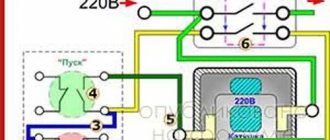
When connecting a three-phase 220V motor, where there is only a phase and a zero, you can resort to a circuit with capacitors.
Execution form and installation method
IM 1081 - form of execution and installation method in accordance with GOST 2479 and IEC60034-5. In our example, this means “foot-mounted with two end shields, with one cylindrical shaft end.”
This name consists of the Latin letters IM and four numbers.
The first digit from 1 to 9 is a constructive method of execution
Second and third (00.99) - installation method
The fourth (0..9) is a symbol for the end of the shaft.
Electric motor efficiency
Efficiency shows the efficiency of an electric motor’s conversion of electrical energy, which it takes from the network, into the mechanical energy of rotation of the mechanism.
If there were no losses during energy transmission, then the efficiency would be 100%. However, this does not exist. However, there are types of losses that reduce the value of the coefficient:
- losses from heating current-carrying conductors with increasing load - electrical losses
- losses due to eddy currents, hysteresis in laminated stators - magnetic losses
- friction losses of bearings, ventilation - mechanical losses
- plus various additional less important types of losses.
Often, but not always, the higher the rotational speed of an electric motor, the greater its efficiency. This is due to the dependence of efficiency and ED slip. There are classes according to the efficiency value according to GOST IEC/TS15: IE1, IE2, IE3, IE4.
Calculation of electric motor efficiency
Online calculation of efficiency (efficiency) of an electric motor
The efficiency of the electric motor is calculated using the following formula:
η=P/√3UIcosφ
- P - Rated power of the electric motor (taken from the motor’s passport data or determined by calculation);
- U - Rated voltage (voltage to which the electric motor is connected);
- I - Rated current of the electric motor (taken from the passport data of the electric motor , and in their absence is determined by calculation);
- cosφ - Power factor - the ratio of active power to total power (taken from 0.75 to 0.9 depending on the power of the electric motor);
Did you find these online calculators useful? Or maybe you still have questions ? Write to us in the comments!
Didn’t find an article on the website on a topic that interests you regarding electrical engineering? Write to us here. We will definitely answer you.
Measure motor power
The power of an electric motor is composed of active and reactive components. Enterprises are subject to a penalty tariff. Therefore, it is important to understand the measured quantities. The instructions for current clamps write: evaluate the root mean square current. Pure mathematics. This means: the device makes a sample of a certain interval, takes the root of the sum of the squares of the individual measurements, divided by the total number. Let's compare it to averaging over a certain period of time.
Active current, total, reactive (hardly). It is useful to clarify the question: the current clamps shown in the photo with enviable regularity give the power of devices 11% below the nominal value. Electric heaters, irons, hair dryers were checked. Power is underestimated by a single value. The literature writes: the root mean square (RMS) value shows the full value of the current. Physically flows along the wire. The calculation is carried out for a sinusoidal shape; there will be deviations if the requirement is not met.
Current clamps are simply lying. If they showed the active part, the values for the engine would be significantly lower than for the heater. The load is purely active, the windings produce a strong imaginary component. It is necessary to calibrate current clamps before use. The easiest way to do this is to use purely active heaters (oil). The ability of current clamps to measure active power separately is usually indicated in the instructions. Professionals say: such products are a figment of the imagination of amateurs.
Engines provide a large load in the reactive spectrum. People put up with it, or install capacitor blocks that compensate for the discrepancy, leveling the phase. You can read about similar household products on websites that sell devices like Econor. The purpose of the box is like a block of capacitors to compensate for reactive power. Please note: for professional stations the limit expressed by VAR is indicated; for Econor the parameter is silent. One radio amateur counted the number. It turned out that 150 VAR is compensated.
Probably, low-power devices will be enough, the engines will use elephant pellets. Asynchronous machines provide 40% of reactive power, energy is wasted. The benefits are pennies. Please note: with an isolated neutral, problems are added. Current flows in in one phase and leaves in another. The effect may be deducted. Current clamps cannot be considered the best option.
It is better if the neutral is grounded. The total current flows out through the neutral wire, where we carry out measurements. The neutral is isolated - it turns out that we will measure the effect of one wire twice: input, output. Try adding the three values, then dividing by two. The rough method will be approximately correct.
Current clamp attachment
Calculation of electric current by power: formulas, online calculation, selection of machine
When designing electrical wiring in a room, you need to start by calculating the current strength in the circuits. An error in this calculation can be costly later. An electrical outlet can melt if exposed to too much current. If the current in the cable is greater than the calculated current for a given material and core cross-section, the wiring will overheat, which can lead to melting of the wire, a break or short circuit in the network with unpleasant consequences, among which the need to completely replace the electrical wiring is not the worst thing.
It is also necessary to know the current strength in the circuit to select circuit breakers, which should provide adequate protection against network overload. If the machine is set with a large margin at its nominal value, by the time it is triggered, the equipment may already be out of order. But if the rated current of the circuit breaker is less than the current that appears in the network during peak loads, the circuit breaker will drive you crazy, constantly cutting off power to the room when you turn on the iron or kettle.
Selecting the rating of the circuit breaker
Applying the formula I = P/209, we find that with a load with a power of 1 kW, the current in a single-phase network will be 4.78 A. The voltage in our networks is not always exactly 220 V, so it would not be a big mistake to calculate the current strength with a small margin like 5 A for every kilowatt of load. It is immediately clear that it is not recommended to connect an iron with a power of 1.5 kW to an extension cord marked “5 A”, since the current will be one and a half times higher than the rated value. You can also immediately “graduate” the standard ratings of the machines and determine what load they are designed for:
- 6 A – 1.2 kW;
- 8 A – 1.6 kW;
- 10 A – 2 kW;
- 16 A – 3.2 kW;
- 20 A – 4 kW;
- 25 A – 5 kW;
- 32 A – 6.4 kW;
- 40 A – 8 kW;
- 50 A – 10 kW;
- 63 A – 12.6 kW;
- 80 A – 16 kW;
- 100 A – 20 kW.
Using the “5 amperes per kilowatt” technique, you can estimate the current strength that appears in the network when connecting household devices. You are interested in peak loads on the network, so for the calculation you should use the maximum power consumption, not the average. This information is contained in the product documentation. It is hardly worth calculating this indicator yourself by summing up the rated powers of the compressors, electric motors and heating elements included in the device, since there is also such an indicator as the efficiency factor, which will have to be assessed speculatively with the risk of making a big mistake.
When designing electrical wiring in an apartment or country house, the composition and passport data of the electrical equipment that will be connected are not always known for certain, but you can use the approximate data of electrical appliances common in our everyday life:
- electric sauna (12 kW) – 60 A;
- electric stove (10 kW) – 50 A;
- hob (8 kW) – 40 A;
- instantaneous electric water heater (6 kW) – 30 A;
- dishwasher (2.5 kW) - 12.5 A;
- washing machine (2.5 kW) - 12.5 A;
- Jacuzzi (2.5 kW) – 12.5 A;
- air conditioner (2.4 kW) – 12 A;
- Microwave oven (2.2 kW) – 11 A;
- storage electric water heater (2 kW) – 10 A;
- electric kettle (1.8 kW) – 9 A;
- iron (1.6 kW) – 8 A;
- solarium (1.5 kW) – 7.5 A;
- vacuum cleaner (1.4 kW) – 7 A;
- meat grinder (1.1 kW) – 5.5 A;
- toaster (1 kW) – 5 A;
- coffee maker (1 kW) – 5 A;
- hair dryer (1 kW) – 5 A;
- desktop computer (0.5 kW) – 2.5 A;
- refrigerator (0.4 kW) – 2 A.
The power consumption of lighting devices and consumer electronics is small; in general, the total power of lighting devices can be estimated at 1.5 kW and a 10 A circuit breaker is sufficient for a lighting group. Consumer electronics are connected to the same outlets as irons; it is not practical to reserve additional power for them.
If you sum up all these currents, the figure turns out to be impressive. In practice, the possibility of connecting the load is limited by the amount of allocated electrical power; for apartments with an electric stove in modern houses it is 10 -12 kW and at the apartment input there is a machine with a nominal value of 50 A. And these 12 kW must be distributed, taking into account the fact that the most powerful consumers concentrated in the kitchen and bathroom. Wiring will cause less cause for concern if it is divided into a sufficient number of groups, each with its own machine. For the electric stove (hob), a separate input with a 40 A automatic circuit breaker is made and a power outlet with a rated current of 40 A is installed; nothing else needs to be connected there. A separate group is made for the washing machine and other bathroom equipment, with a machine of the appropriate rating. This group is usually protected by an RCD with a rated current 15% greater than the rating of the circuit breaker. Separate groups are allocated for lighting and for wall sockets in each room.
DC motors
Based on Newton's principle of mechanics, which states that all motion is relative, a DC electric motor can be called a synchronous machine. Although the magnetic fields of the stator and rotor are stationary in it, the rotation of the shaft occurs due to the effect of repulsion of like poles of magnets and attraction of unlike poles.
Their position relative to each other is synchronized by a special device - a collector located on the rotor shaft. This is a copper ring divided into sectors by a dielectric. The ends of the rotor windings are connected to these sectors and create contact pairs.
They are supplied with direct current through carbon brushes. As the shaft rotates, poles switch between pairs. The stator magnetic field can be created by metals with residual magnetism or by the passage of current through the windings. The latter are used in high-power electric machines.
Their advantage is a high efficiency, up to 98%, as well as consistently high torque and low dependence on overloads. DC motors are excellent for driving lifting mechanisms, as well as for traction in electric vehicles.
They are very easy to control: to reduce the rotation speed, you just need to reduce the amount of applied voltage, and to reverse it, just change the polarity. The disadvantage is the complexity of the device and the low reliability of the brush assembly, its tendency to spark and be noisy. In addition, DC voltage is difficult to transmit over long distances, which is why there are no main lines of this type. You will have to create the power yourself, using rectifier or inverter circuits. You can also read about DC motors here.
Brushed motors
They are similar in design to DC motors. However, they are powered by single-phase alternating current. Their stator field winding is connected in series with the armature winding. The rotation of the shaft occurs due to the synchronous change of poles of the magnetic field in the stator and rotor windings.
The advantages listed above - high torque, insensitivity to overloads - also include the fact that this is the only AC electric machine that can be controlled without problems.
To change the shaft rotation speed, it is enough to reduce the supply voltage, and to reverse it, swap the connection points of the collector unit with the stator winding. Therefore, commutator motors are widely used in household electrical appliances.
For example, in washing machines, drills and other electrified tools. The disadvantages, the main of which is the complexity and low reliability of the brush assembly, include the inability to connect three-phase voltage. Simply because in this case there should be six brushes. This limits the maximum power of the motors: for single-phase machines at a voltage of 220 volts, this value does not exceed 2.5 kilowatts.
Asynchronous electrical machines
In them, the magnetic field of the rotor is a product of the rotating magnetic field of the stator. Since there is an air gap between these machine parts, energy transfer between them occurs with losses. Therefore, the phase of the current in the rotor lags behind the phase of the current in the stator by a small angle (no more than 100), which determines the value of the power factor cosφ. This lag is the reason why an electric machine of this type is called asynchronous.
Squirrel-cage motors
Their rotor winding is a set of metal rods that connect two rings. The resulting figure is called a “squirrel wheel”. At the moment voltage is applied to the stator winding, a short circuit current arises in the rotor, the energy of which is spent on unwinding the shaft and is thereby extinguished. It has a slightly lower efficiency than synchronous machines, it does not exceed 80%.
After gaining speed, it has a very stable torque on the shaft and can withstand overloads well. The main advantages of such engines are their simplicity and reliability, thanks to which they are very widespread. Disadvantages: complexity of management.
To change the rotation speed, it is necessary to change the frequency of the supply voltage or the number of stator windings, which determines the number of poles of the electromagnet - the more there are, the lower it is. Also, electric motors with a squirrel-cage rotor are characterized by a large starting current that overloads the network, as well as a sharp increase in torque when power is connected, which can cause damage to the drive gearbox.
Wound rotor motors
The start-up of high-power squirrel-cage asynchronous motors (more than 30 kW) is associated with extreme overload of the supply network. To eliminate this phenomenon, machines with a wound rotor are used, the winding of which consists of three coils connected by a star. Their ends are connected by carbon brushes to three slip rings located on the motor axis.
Unlike a DC motor commutator, they are not divided into sectors. When starting such a machine, a three-phase rheostat is used, the resistance of which is maximum at the moment of start-up. By gradually reducing the active resistance of the rotor, a smooth rotation of the electric motor shaft is achieved. When the nominal speed is reached, it is short-circuited.
By changing the rotor resistance, you can change the rotation speed. The advantage of a machine of this type is the absence of overload at the time of start-up and a smooth increase in torque. Therefore, it is used in lifting equipment. The disadvantage is the complexity of the device and lower efficiency than that of machines with a squirrel-cage rotor, it is no more than 60%.