Technical data VA47−29
All models in this line are inexpensive, but do an excellent job with the protective functions provided by the design, and have been in use in residential and industrial buildings for a long time. The table shows the technical characteristics of the VA 47−29 circuit breaker:
| Indicators | Values |
| Network voltage (variable), V | 230; 400 |
| Operating current - nominal, A | Integer: 1–6, 8, 10, 13, 16, 20, 25, 32, 40.50, 63 Fractional: 0.5; 1.6; 2.5 |
| Frequency, hertz | 50 |
| Ultimate breaking capacity, A | 4500 |
| Degree of protection against touching - GOST 14254 | IP20 |
| Wear resistance, cycles: commutation/general | 4000/10000 |
| Cross-sectional area of wires connected to the terminals, mm2 | 1,5÷25 |
| Response time of electromagnetic disconnector B, C, D, seconds | <0,1 |
| Dimensions of a single machine LxWxH, mm | 84x18x75 |
| Weight of a single pole, kg | 0,1 |
There are some differences in the technical characteristics of the VA 47−29 and the similar modified model VA47−29M: the latter machines have a latch on the DIN mounting rail in a double fixed state. The switch handle is wider and has a larger area, and the body with increased heat dissipation helps to increase the current limit by 10%.
Connecting circuit breakers
Switches S201P C are equipped with terminals: 35 mm + 10 mm (for devices up to 2 2 63A), and 50 mm + 10 mm 2 2 (for devices 80, 100 A) for separate connection of busbar wiring and cables - cylindrical bidirectional terminals with protection from improper installation, resistant to impact, which are accessible even after installing a modular machine. In the absence of bus wiring, it is possible to connect two pairs of conductors of different cross-sections. S201 P C have special clamping jaws for quick installation of the circuit breaker on a DIN rail located in distribution boards, boxes and cabinets. If the product is replaced, the same lock allows you to quickly dismantle it. For ease of cable installation, the switches are equipped with captive screw technology, and the degree of protection against finger contact in the connection area reduces the risk of electric shock and the possibility of a short circuit.
Connection diagram S201 P C:
Marking of machines
Circuit breaker marking
Each machine has its own marking, which consists of alphanumeric and conventional graphic images used to identify and convey to the consumer its main technical characteristics. They are necessary for the correct selection and further operation of the machine.
- manufacturer's name or trademark;
- designation of type, catalog number or series number;
- rated voltage value;
- rated current values without the symbol “A” with the preceding designation of the type of protective characteristic (A, B, C, D, K, Z) and current limiting class;
- rated frequency value;
- the value of the rated maximum breaking capacity in amperes;
- connection diagram if the correct connection method is not obvious;
- the value of the control ambient temperature, if it differs from 30 °C;
- degree of protection, unless it differs from IP20;
- for type D circuit breakers, the maximum value of the instantaneous tripping current, if it is higher than 20In;
- value of rated impulse withstand voltage Uimp.
The marking of difavtomats is similar to the AB marking, but contains additional information:
- rated residual current;
- settings of the disconnecting differential current (for DV with several values of the disconnecting differential current);
- rated maximum differential making and breaking capacity;
- a button with the symbol “T” for operational monitoring of the performance of the DV by differential current;
- symbol “~” – for DV type AC;
- symbol for DV type A.
Explanation of circuit breaker symbols
Along with the marking of the switches, the necessary information about the characteristics and type of the AV contains its symbol, which is required to place an order for the purchase of the AV.
The symbol of the circuit breaker is as follows: VA47-Х1-Х2Х3Х4ХХ5-УХЛ3
Explanations for the symbol AB are given in the table.
| Symbol | Decoding |
| VA47 | Switch series designation |
| X1 | Switch type |
| X2 | Number of poles |
| X3 | The letter “N” in the presence of a pole without a release |
| X4 | Type of protective characteristic |
| XX5 | Rated operating current |
| UHL3 | Designation of climatic version and placement category (according to GOST 15150) |
Examples of writing AB notation:
- single-pole circuit breaker with a protective characteristic of type “C” for a rated current of 16 A: Switch VA47-29-1S16-UHL3
- four-pole circuit breaker with a protective characteristic of type “C” with an unprotected pole for a rated current of 100 A: Switch VA47-100-4NC100-UHL3.
For products of the UHL3 design, the operating temperature range is from minus 60 to +40 °C.
Marking of S201 P C machines
The housing of the S201 P C series circuit breakers contains all the necessary markings, such as:
- - manufacturer;
- — model;
- — rated current and type of response characteristic;
- — operating voltage of the network;
- — breaking capacity;
- — current limitation class;
- — schematic diagram of the switch operation.
ABB circuit breakers comply with IEC/EN 60898-1 and IEC/EN 60947-2 standards and carry all relevant certification marks for each market and segment for which they are designed. Certification marks are also printed on the circuit breaker body. For the inspection and acceptance procedure, certification marks are clearly visible on the body. All markings are made using laser printing technology, which is resistant to abrasion and solvents, which ensures a long service life and ease of product identification.
Features of switches BA 47 29
- The design of setting the thermal release settings by screwing the adjusting screw into the metal base allows you to avoid changing the settings during operation.
- The main contacts of the machine are coated with silver-containing material, identical in composition to similar products manufactured by ABB, Schnider Electric, Legrand.
- The original design of the BA 4729 contacts reduces losses between the conductor and the switch terminals.
- The moving contacts inside the switch are silver plated for increased service life and durability.
- The high-speed contact release system of the VA 4729 machine does not allow the current to reach peak values during a short circuit.
- Possibility of connecting conductors with a diameter of up to 20 mm.
- Electrical durability over 6000 on/off cycles
- Mechanical 2000 shut-off cycles
- Possibility of arbitrary placement in space.
Explanation of designations of the BA 4729 IEK series
Automatic VA 47-29 VA 4729 series of circuit breakers number of poles 1,2,3,4XX overload current setting XX short circuit response characteristic B 3-5 are designed to protect active loads and long lighting lines with TN and IT grounding systems (sockets , lighting).C 5-10 are designed to protect circuits with active and inductive loads with low pulse current (compressor, fan) D 10-20 is used for loads with high pulse (starting) currents and increased switching current (low-voltage transformers, lamps - arresters, lifting mechanisms, pumps)
Questions and answers about the BA 4729 IEK series
What do the letters B, C, D mean in the designation of modular machines?
Short circuit response characteristics. Selected according to the type of load that the machine will protect
B 3-5 are designed to protect active loads and long lighting lines with TN and IT grounding systems (for kettles, water heaters, etc.).
C 5-10 are designed to protect circuits with active and inductive loads with low pulse current (used in 90% of cases when installed in apartments and residential premises.)
Usually, machines with characteristic C are installed in apartments.
D 10-20 is used for loads with high pulse (starting) currents and increased switching current (low-voltage transformers, arresters, lifting mechanisms, pumps) K 8-15 active-inductive load, electric motors, transformers Z 2-3 electronics
Below are the time-current characteristics of machines with characteristic B (curve 1) and with characteristic C of curve 2
How to choose machines to build a selective circuit in an apartment?
If you want to build a selective circuit for overload current, then in this case it will be enough to simply build a circuit with an increase in the ratings of higher-level circuit breakers. That is, for example, we install a 16A circuit breaker on the outlet line, and a 25A input circuit breaker.
Constructing a short circuit selective circuit is much more difficult. Here you need to use selectivity tables from manufacturers’ catalogs.
Although some designers, in their projects, try to build a selective circuit of automata according to the response characteristics (indicate lower-level automata with characteristic B, and higher ones with characteristic C or D). Which is probably not the best decision
Application of single-pole circuit breakers S201P C
Modular circuit breakers S201P C, as a rule, have all possible designs according to the operating characteristics of circuit breakers, which indicates their wide application segment. They are usually used for surge protection by installing on a DIN rail in distribution boards, boxes located in residential buildings, offices, warehouses, and other industrial and commercial premises. S201 P C is used to protect circuits with active and inductive loads and low pulse current (providing electricity to apartments, offices, industrial facilities).
Advantages of BA 47-29 switches
Among the advantages of modular circuit breakers are:
- Non-separable design with four (Russia) or six (China) rivets that connect all parts of the body.
- Availability of contact position indicator. Lights up green when they are open, or lights up red when the system is energized when the contacts are engaged.
- Availability of combined protection against exposure to overcurrents on electrical networks. The thermal release responds in a timely manner to the occurrence of any overloads in the network, while the electromagnetic release is triggered if it detects the occurrence of a short circuit in the network.
- The standard module width is 18 mm and corresponds to the width of one pole. For example, if you buy a three-pole machine BA47-29, its width will be 54 mm.
- Spring-loaded locking mechanism allows the device to be easily mounted on a DIN rail.
- A seal used to secure the screws of the contact terminals.
- Ribbed surfaces of the clamps, which ensures effective fixation of the connected cores.
- The switching capacity is 4.5 kA (the maximum short circuit current switched by this equipment), which is quite sufficient for domestic use.
The BA 47-29 machine is an inexpensive and practical option for ensuring the safety of electrical networks in any modern home.
What is a single pole circuit breaker?
AB is a switching contact device designed to protect electrical distribution networks from overloads and short circuits. When switched on, a current flows through the device, the value of which corresponds to the device rating.
Application area
Single-pole circuit breakers provide voltage supply to consumers and protect the circuit from overloads.
In everyday life, devices have replaced fuses, often popularly called “plugs”.
Advantage over traffic jams:
- Restoring functionality by simply lifting a lever or pressing a button.
- The characteristics of the device do not change after repeated manual on/off cycles and emergency operations. This is in contrast to traffic jams, where “masters” installed “bugs”, repeatedly increasing the network capacity, which led to fires.
At home, devices for protecting one wire - single-pole AB - have become widespread; we will discuss them below.
General structure and principle of operation
Single-pole AVs consist of several functional parts:
- housings;
- working contact system;
- arc extinguishing device;
- releases and drive.
Releases - elements that protect the circuit, can be electromagnetic and thermal.
The electromagnetic release is a coil with a spring-loaded movable core. By moving, the core controls the position of the associated moving contact, which closes the circuit.
In normal consumption mode, the force of electromagnetic induction created by the current flowing through the coil is not enough to overcome the elasticity of the spring. Voltage is supplied to the network, and current flows through consumer devices.
When a short circuit occurs, the current through the coil increases many times. The force created by electromagnetic induction overcomes the resistance of the spring. The core, moving in the coil, opens the contacts.
The working body of the thermal release is a bimetallic plate that controls the closure of the contacts.
When devices with a total power exceeding the AB rating are connected to the network, an increased current flows through the plate. When heated, it deforms and at a given value turns off the AV.
An important design element that increases service life is the arc chute. It is needed to extinguish the spark between the contacts that appears during opening.
Versions VA47-29
Article Name Price
A8224-MVA20-1-001-B
order 10 days
Automatic switch VA47-29, 1 pole, 1A, characteristic B
Automatic switch VA47-29, 1 pole, 1A, characteristic B
189.60
A8224-MVA20-1-001-C
= 23 pcs.
Automatic switch VA47-29, 1 pole, 1A, characteristic C
Automatic switch VA47-29, 1 pole, 1A, characteristic C
180.72
A8224-MVA20-1-001-D
order 10 days
Automatic switch VA47-29, 1 pole, 1A, characteristic D
Automatic switch VA47-29, 1 pole, 1A, characteristic D
208.56
A8224-MVA20-1-002-B
order 10 days
Automatic switch VA47-29, 1 pole, 2A, characteristic B
Automatic switch VA47-29, 1 pole, 2A, characteristic B
189.60
A8224-MVA20-1-002-C
= 29 pcs.
Automatic switch VA47-29, 1 pole, 2A, characteristic C
Automatic switch VA47-29, 1 pole, 2A, characteristic C
180.72
A8224-MVA20-1-002-D
order 10 days
Automatic switch VA47-29, 1 pole, 2A, characteristic D
Automatic switch VA47-29, 1 pole, 2A, characteristic D
208.56
A8224-MVA20-1-003-B
order 10 days
Automatic switch VA47-29, 1 pole, 3A, characteristic B
Automatic switch VA47-29, 1 pole, 3A, characteristic B
189.60
A8224-MVA20-1-003-C
= 4 pcs.
Automatic switch VA47-29, 1 pole, 3A, characteristic C
Automatic switch VA47-29, 1 pole, 3A, characteristic C
180.72
A8224-MVA20-1-003-D
order 10 days
Automatic switch VA47-29, 1 pole, 3A, characteristic D
Automatic switch VA47-29, 1 pole, 3A, characteristic D
208.56
A8224-MVA20-1-004-B
order 10 days
Automatic switch VA47-29, 1 pole, 4A, characteristic B
Automatic switch VA47-29, 1 pole, 4A, characteristic B
189.60
A8224-MVA20-1-004-C
= 1 piece
Automatic switch VA47-29, 1 pole, 4A, characteristic C
Automatic switch VA47-29, 1 pole, 4A, characteristic C
180.72
A8224-MVA20-1-004-D
order 10 days
Automatic switch VA47-29, 1 pole, 4A, characteristic D
Automatic switch VA47-29, 1 pole, 4A, characteristic D
208.56
A8224-MVA20-1-005-B
order 10 days
Automatic switch VA47-29, 1 pole, 5A, characteristic B
Automatic switch VA47-29, 1 pole, 5A, characteristic B
189.60
A8224-MVA20-1-005-C
= 13 pcs.
Automatic switch VA47-29, 1 pole, 5A, characteristic C
Automatic switch VA47-29, 1 pole, 5A, characteristic C
180.72
A8224-MVA20-1-005-D
order 10 days
Automatic switch VA47-29, 1 pole, 5A, characteristic D
Automatic switch VA47-29, 1 pole, 5A, characteristic D
208.56
A8224-MVA20-1-006-B
order 10 days
Automatic switch VA47-29, 1 pole, 6A, characteristic B
Automatic switch VA47-29, 1 pole, 6A, characteristic B
151.44
A8224-MVA20-1-006-C
= 26 pcs.
Automatic switch VA47-29, 1 pole, 6A, characteristic C
Automatic switch VA47-29, 1 pole, 6A, characteristic C
138.36
A8224-MVA20-1-006-D
order 10 days
Automatic switch VA47-29, 1 pole, 6A, characteristic D
Automatic switch VA47-29, 1 pole, 6A, characteristic D
186.60
A8224-MVA20-1-008-B
order 10 days
Automatic switch VA47-29, 1 pole, 8A, characteristic B
Automatic switch VA47-29, 1 pole, 8A, characteristic B
189.60
A8224-MVA20-1-008-C
= 11 pcs.
Automatic switch VA47-29, 1 pole, 8A, characteristic C
Automatic switch VA47-29, 1 pole, 8A, characteristic C
180.72
- 1
Cable Requirements
You can already understand that not every cable is suitable for connecting such equipment. This is logical, since under heavy overloads it will simply burn out and can cause equipment failure or a fire. Therefore, when choosing a cable for an electric stove, you should rely on the following important characteristics:
- Rated voltage;
- material that serves as the basis for wire cores;
- cable section;
- ease of connection to the device.
If we take the rated voltage for devices of well-known brands, then its value must be exactly no less than that provided by the conventional electrical network where the device needs to be connected. Now let's say a little more about the described indicators.
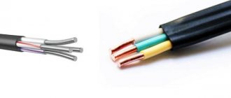
Probably one of the most important aspects that will play a role is the material used to make the cable cores. It's best if they are copper. This metal itself can be soldered if necessary. And the copper power wire is more flexible than its aluminum counterpart. But the cost of a copper solution will be higher. If the choice falls on an aluminum analogue, then you need to understand that its installation should not be carried out in materials that burn. You can find out what the electrical wire is made of thanks to special markings on the product itself.
If we talk directly about numbers, then, as a rule, most solutions from well-known brands (Samsung or Electrolux) are designed for electricity consumption of just under 4 kW. For this reason, the safety margin of the wire needs to be selected based on power somewhere with a focus on this indicator.
To ensure that the device operates as safely as possible, you should also pay attention to the following points:
- If you need to lay the cord directly from the panel to the electric stove, a cord with a standard cross-section of 1.5 square meters is sufficient. mm.
- If other electrical appliances will be connected between the device and the panel, then you should have a cable with a cross-section of at least 2.5 square meters. mm. This option will provide the necessary reserve in case of connecting some other household appliances.
Another important parameter is the phase connection. It will depend on the number of cores in the cable. The wire can be 3 or 5 wires. The number of cores will depend on the power supply network in the room. And it can be either 1-phase or 3-phase. If the first option, then you will need to purchase a wire with three cores, and if the second - with five.
You should also find out whether the purchased equipment supports the type of connection that was selected. For example, stoves with a power of up to 5 kW are usually connected to a 1-phase network, while more powerful ones have a 2 or 3-phase connection. The type of cable that can be used will also be important, but more on that below.
Features of the design of the circuit breaker
- VA 47-29 has an improved design of the arc extinguishing system, which ensures the best characteristics of the circuit breaker when turning it on and off. Installing such a system prevents contacts from burning, and this ensures a longer service life. It also allows for increased protection against short circuit currents. The design of the circuit breaker corresponds to patent No. RU 139886.
- The design of the device provides the possibility of combining the FORK bus and connecting wires at the same time. For this purpose, additional upper clamps are provided. You can also install a PIN bus in them, which is used when building complex power distribution networks. A more reliable and vibration-resistant connection is provided due to the improved design of the clamping bar and serrated socket. The latest innovation contributes not only to the pressing effect, but also to jamming the wire in the socket, ensuring its reliable contact.
- In addition to the improved contact connection design, the circuit breaker is equipped with non-stick protection. This is ensured by installing an additional spacer with a metal heat sink. The device is coated with a special coating, which helps extinguish the arc, eliminating melting of the housing.
- All contact groups are coated with a silver-containing alloy by soldering, which helps to extend the service life of the contact group, eliminating burning and sticking. In addition, the coating helps reduce contact resistance, which increases the efficiency of the device.
- Increased contact area of contacts, which provides more efficient heat dissipation and reduces the likelihood of overheating of the structure in the event of an increase in load current.
- The body has increased strength due to the monolithic front wall and the presence of additional rivets. The thickness of the plastic has also been slightly increased and some kind of stiffening ribs have been applied in the form of longitudinal protrusions.
- VA47-29 is equipped with a contact position indicator. Accordingly, when they are closed it is green, when open it is red. And for quick installation and dismantling, a spring-loaded mechanism with a lever for pulling the locking device is provided.
Technical characteristics of the circuit breaker
VA 47-29, being a safety device for emergency load disconnection from power circuits, is calculated primarily for the maximum operating current or tripping current. This is the value at which the security system is triggered. For this brand of switch, I trip will be 255% of the nominal. In this case, the shutdown time will take 1 s.
In addition to the rated current, when exceeded, automatic shutdown occurs, there is such a parameter as the number of on-off cycles. But this indicator is set separately for electrical and mechanical wear resistance. In the first case, it is capable of operating stably for 6000 cycles.
The machine is designed to operate with alternating voltage up to 400 V and constant voltage up to 48 V at the same shutdown current value. As for the number of contact groups, the machine can be single, paired, triple or with 4 contact pairs. Accordingly, it can be used in three-phase and single-phase power circuits.
The design of the switch has low protection from external factors, in particular, dust and moisture - IP 20. Therefore, it must be mounted in closed electrical distribution cabinets.
Selecting a circuit breaker
The choice of switches is mainly carried out according to the load power and the cross-section of the connected wire, taking into account 2 parameters: overload current and short-circuit shutdown current.
Current overload occurs when devices and devices are connected to the network, the total power of which will lead to excessive heating of conductors and contact connections. Therefore, the machine that will be installed in a specific circuit must have a shutdown current greater than the so-called reserve or equal to the calculated one. It is determined by summing the power of the electrical devices intended for use, which is often indicated in the passport. Next, the resulting figure is divided by 220 and our overload current is obtained. One more important circumstance should also be taken into account: this current should not be greater than the current that can flow through the conductor.
The shutdown current during a short circuit is the value at which the circuit breaker turns off; it is also called cutoff. It is also calculated and then selected according to the type of protection. The type of protection contains the values of the shutdown current in relation to the probable short-circuit current, depending on the type of load in the electrical network. In everyday life and for small objects, devices are used with the symbol characteristics B, C, and at the input - D. Most often, in addition to the circuit breakers for each group line, the electrical circuit also includes an input circuit breaker, an RCD or a differential circuit. machine.
Marking and operating conditions
Some of the characteristics of the BA47−29 are contained in the designation of the switch model. The following signs are used that make up the marking after the abbreviation BA:
- 47 — product serial number;
- XXX - digital modification code;
- X - letter indicator of the protective characteristic: overload capacity B, C, D;
- XX - rated current of the machine, ampere;
- X is the number of poles (1, 2, 3, 4).
The main advantages of the switch are: silver on the contacts, notches on the clamps - they prevent overheating and melting of the wires at the points of their connection.
The device is capable of operating at an altitude of up to 2 thousand meters above sea level in an atmosphere from -40 to 50ºС for at least 15 years, it can be placed in any position.
Description
According to its characteristics, VA 47-29 is a high-speed release that will provide instant shutdown of circuits in which an unauthorized overcurrent has occurred. The device can be used for purposes with different types of loads, disconnecting them from power with the same quality and efficiency.
The shutdown speed depends on the type of load, which is expressed by the letter A, B, C:
- For loads such as lighting, soldering iron equipment and other electrical appliances with low current consumption are switched through switches with index B.
- To control motors with low current consumption, category C automatic machines are used.
- Loads with high currents are controlled using switches with index D.
The acceptable characteristics of VA 47-29 made it possible to use them in the domestic sphere for switching general-purpose loads: lighting, ventilation systems, various household appliances. The price of the device depends on the index. VA 47-29 with a steeper characteristic have a higher price. The cheapest components are those with the letter D.
Handymen will be interested in an article about the characteristics and connection diagram of the KU202N thyristor.
Ease of installation
- Possibility of sealing to protect against unauthorized access (plug supplied separately).
- The universal head of the reinforced terminal clamp screw allows you to use any screwdriver and provide the necessary tightening force.
- Detailed installation and operating instructions make it easy to install the machine even for a novice installer. The din-rail latch with fixation simplifies installation and dismantling of the device.
- The device implements the possibility of double simultaneous connection of a bus and a conductor, which allows you to significantly expand the range of possible circuit solutions.
- The terminals of the device are marked and signed (Network/Load), which allows you to avoid installation errors.
- BA47-29 switches can be installed in any position without changing their nominal characteristics. The supply line can be supplied both through the upper and lower terminals, without disrupting operation.
- Detailed installation and operating instructions make it easy to install the machine even for a novice installer.
Types of DIN rails
Installing a circuit breaker on a DIN rail
Depending on the shape of the mounting strip, known examples of products of this class are divided into the following types:
- TN type rails (their varieties are TN 15, TN 35, TN 75);
- class “C” products (C20, 30, 40, 50);
- G-type strips (G 32).
The first of these designs is shaped like the letter of the Greek alphabet “omega” and is the most common among industrially produced samples. The housings of electricity meters and automatic machines are traditionally mounted on it.
In C-shaped models, the side edges are curved inward, so its profile allows you to fix terminal blocks of a special shape and design. The G-bar is a slightly modified modification, used extremely rarely and used for the same purposes. The length of these fasteners, depending on the manufacturer, varies from 7.5 cm to 2 meters, which allows you to place on them from 4 to 96 pieces of protective devices with the standard width of one machine module.
According to their design, DIN rails can be perforated - with holes filled along the entire length - and solid or cast.
The advantage of the first designs is ease of installation, since if there are holes drilled in increments of 10-15 mm, it is much easier to attach a steel rail. But cast samples are more durable and reliable. They are not deformed if there are a large number of circuit breakers in the distribution panel.
Application and design of switches
BA series machines are used not only in housing construction, but also in factories, power plants, mines and other industrial facilities. Main elements and blocks of the protective device:
- housing with markings and an indicator of switching directions;
- control handle;
- contacts made of an alloy including silver;
- knurled clamps for securing external wires;
- electromagnetic release coil and its bimetallic plate;
- chamber for extinguishing the electric arc;
- mounting base with a lock for the rail.
Operating principle: due to an overload in the network, a part made of double metal bends and acts on the free release lever - the protection is triggered. When a short circuit occurs, the multiplying current in the coil shifts the core and the circuit opens. In both cases, an electric arc occurs on the contacts - it is for this that an arc-extinguishing chamber is provided in the design of the machine.
Obviously, if the washing machine, heater and iron are turned on at the same time, an overload will occur and the protection will work, disconnecting the entire apartment circuit with appliances from the power supply. To distribute power, the wiring in the premises is divided into two or three groups, with each of them connected to its own circuit breaker with a certain current rating.
Circuit breakers
To bookmarks
In this article we will consider the following questions:
- What is a circuit breaker?
- Design and principle of operation of a circuit breaker.
- Marking and characteristics of circuit breakers.
- Selecting a circuit breaker.
What is a circuit breaker?
A circuit breaker (circuit breaker) is a switching device designed to protect the electrical network from overcurrents, i.e. from short circuits and overloads.
The definition of “switching” means that this device can turn on and off electrical circuits, in other words, switch them.
Automatic circuit breakers come with an electromagnetic release that protects the electrical circuit from short circuits and a combined release - when in addition to the electromagnetic release a thermal release is used to protect the circuit from overload.
Note: In accordance with the requirements of the PUE, household electrical networks must be protected from both short circuits and overloads, therefore, to protect household electrical wiring, circuit breakers with a combined release should be used.
Automatic switches are divided into single-pole (used in single-phase networks), two-pole (used in single-phase and two-phase networks) and three-pole (used in three-phase networks), there are also four-pole circuit breakers (can be used in three-phase networks with a TN-S grounding system).
Design and principle of operation of a circuit breaker.
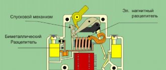
The figure below shows the design of a circuit breaker with a combined release, i.e. having both an electromagnetic and thermal release.
1,2 - respectively lower and upper screw terminals for connecting the wire
3 - moving contact; 4—arc chamber; 5 - flexible conductor (used to connect moving parts of the circuit breaker); 6 - electromagnetic release coil; 7 - core of the electromagnetic release; 8 — thermal release (bimetallic plate); 9 — release mechanism; 10 — control handle; 11 — clamp (for mounting the machine on a DIN rail).
The blue arrows in the figure show the direction of current flow through the circuit breaker.
The main elements of the circuit breaker are electromagnetic and thermal releases:
The electromagnetic release provides protection of the electrical circuit from short circuit currents. It is a coil (6) with a core (7) located in its center, which is mounted on a special spring. In normal operation, current passing through the coil according to the law of electromagnetic induction creates an electromagnetic field that attracts the core inside the coil, but the strength of this electromagnetic field is not enough to overcome the resistance of the spring on which the core is installed.
During a short circuit, the current in the electrical circuit instantly increases to a value several times higher than the rated current of the circuit breaker; this short circuit current, passing through the coil of the electromagnetic release, increases the electromagnetic field acting on the core to such a value that its retraction force is enough to overcome the resistance springs, moving inside the coil, the core opens the moving contact of the circuit breaker, de-energizing the circuit:
In the event of a short circuit (i.e., with an instantaneous increase in current several times), the electromagnetic release disconnects the electrical circuit in a fraction of a second.
The thermal release protects the electrical circuit from overload currents. Overload can occur when electrical equipment is connected to the network with a total power exceeding the permissible load of this network, which in turn can lead to overheating of the wires, destruction of the insulation of the electrical wiring and its failure.
The thermal release is a bimetallic plate (8). Bimetallic plate - this plate is soldered from two plates of different metals (metal “A” and metal “B” in the figure below) having different coefficients of expansion when heated.
When a current exceeding the rated current of the circuit breaker passes through the bimetallic plate, the plate begins to heat up, while metal “B” has a higher expansion coefficient when heated, i.e. when heated, it expands faster than metal “A”, which leads to curvature of the bimetallic plate; as it bends, it affects the release mechanism (9), which opens the moving contact (3).
The response time of the thermal release depends on the amount of excess current in the electrical network of the rated current of the machine; the greater this excess, the faster the release will operate.
As a rule, the thermal release operates at currents 1.13-1.45 times higher than the rated current of the circuit breaker, while at a current 1.45 times higher than the rated current, the thermal release will turn off the circuit breaker in 45 minutes - 1 hour.
The operation time of circuit breakers is determined by their time-current characteristics (VTC)
Whenever the circuit breaker is turned off under load, an electric arc is formed on the moving contact (3), which has a destructive effect on the contact itself, and the higher the switched current, the more powerful the electric arc and the greater its destructive effect. To minimize damage from an electric arc in a circuit breaker, it is directed to the arc-extinguishing chamber (4), which consists of separate, parallel-installed plates; when the electric arc falls between these plates, it is crushed and extinguished.
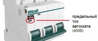
3. Marking and characteristics of circuit breakers.
VA47-29 - type and series of circuit breaker
Rated current is the maximum current of the electrical network at which the circuit breaker is capable of operating for a long time without emergency shutdown of the circuit.
Standard values of rated currents of circuit breakers: 1; 2; 3; 4; 5; 6; 8; 10; 13; 16; 20; 25; 32; 35; 40; 50; 63; 80; 100; 125; 160; 250; 400; 630; 1000; 1600; 2500; 4000; 6300, Ampere.
Rated voltage - the maximum network voltage for which the circuit breaker is designed.
PKS is the maximum breaking capacity of the circuit breaker. This figure shows the maximum short circuit current that can turn off a given circuit breaker while maintaining its functionality.
In our case, the PKS is indicated at 4500 A (Ampere), this means that with a short circuit current (short circuit) less than or equal to 4500 A, the circuit breaker is able to open the electrical circuit and remain in good condition, if the short circuit current. exceeds this figure, there is a possibility of the movable contacts of the machine melting and welding them to each other.
Trip characteristic - defines the tripping range of the circuit breaker's electromagnetic release.
For example, in our case, a machine with characteristic “C” is presented; its operating range is from 5·In to 10·In inclusive. (Iн is the rated current of the machine), i.e. from 5*32=160A to 10*32+320, this means that our machine will provide instantaneous disconnection of the circuit already at currents of 160 - 320 A.
The response characteristic is one of the parameters of the time-current characteristics of circuit breakers, for more details, read the article: “Time-current characteristics (TCC) of circuit breakers”
Note:
- Standard response characteristics (provided for by GOST R 50345-2010) are characteristics “B”, “C” and “D”;
- The scope of application is indicated in the table according to established practice, but it may be different depending on the individual parameters of specific electrical networks.
Selecting a circuit breaker
Note: Read the full methodology for calculating and selecting circuit breakers in the article: “Calculation of the electrical network and selection of protection devices”
The choice of machine is carried out according to the following criteria:
— By the number of poles: one- and two-pole are used for a single-phase network, three- and four-pole are used in a three-phase network.
— By rated voltage: The rated voltage of the circuit breaker must be greater than or equal to the rated voltage of the circuit it protects:
U nom. AB ⩾ U nom. networks
— By rated current: You can determine the required rated current of the circuit breaker in one of the following four ways:
- Using our calculator for calculating the machine's power.
- Using our calculator for calculating the machine according to the cable cross-section.
- Using the following table:
- Calculate yourself using the method given in the article: “Calculation of the electrical network and selection of protection devices”
— Selecting the response characteristic : often the response characteristic of a circuit breaker is selected based on the purpose of the network it protects (according to the table of response characteristics above), however, a machine selected in this way may not ensure timely shutdown of the circuit in the event of a short circuit; the response characteristic must be determined according to the method given here.
Was this article useful to you? Or maybe you still have questions ? Write in the comments!
Didn’t find an article on the website on a topic that interests you regarding electrical engineering? Write to us here. We will definitely answer you.
↑ Up
10
https://elektroshkola.ru/apparaty-zashhity/avtomaticheskie-vyklyuchateli/
Motor protection
If the system uses a circuit breaker belonging to protective class C, when the installation is started, when the currents reach ten rated values or even exceed this figure, false operation of the equipment may occur. To eliminate such a risk, in the vast majority of cases, modular devices belonging to protective class D are used.
It is important to ensure that the system is reliably protected from overload currents, which ultimately have a very negative impact on the life of the insulation used. The switch should be located as close as possible to the electric motor, and a thermal relay is best installed on the starter in order to achieve equal temperature operating conditions for this equipment
It often happens that the thermal release operates in vain, being influenced by any heat sources, or does not work at all if it is in low temperature conditions.