Sectional switch purpose
Let's consider the principle of operation of ATS circuits using the example of a two-transformer substation shown in Fig.
3.2. Normally, both transformers T1 and T2 are turned on and supply the consumers of the low voltage bus sections. Rice. 3.2. (see scan) Diagram of automatic transfer switch of a sectional switch at a substation: a - diagram of primary connections; b - alternating voltage circuits; c - operational current circuits
When switch Q1 of transformer 77 is turned off for any reason, its auxiliary contact SQL2 opens the circuit of the intermediate relay winding KL1. As a result, the armature of relay KL1, pulled up when the switch is in the on position, drops off after a certain time delay when the voltage is removed and opens the contacts.
The second auxiliary contact SQ1.3 of switch Q1, having closed, supplies a plus through the still closed contact KL1.1 to the winding of the intermediate relay KL2, which with its contacts turns on the sectional switch Q5, acting on the switching contactor YAC.5. After the set time delay has expired, relay KL1 opens the contacts and breaks the winding circuit of the intermediate relay KL2. If sectional switch Q5 is turned on by the action of the ATS circuit on an unresolved short circuit and is turned off by relay protection, then it will not be turned on again. Thus, relay KL1 provides one-time operation of the ATS and is therefore called a one-time switching relay. Relay KL1 will close its contacts again and prepare the ATS circuit for a new action only after the normal power supply circuit of the substation is restored and the QL switch is turned on. The time delay for opening the KL1 contact must be greater than the switching time of the Q5 switch in order for them to turn on reliably.
In order to provide ATS, when switch Q2 is disconnected, a command is sent from its auxiliary contact SQ2.2 to the trip coil YAT1 of switch Q1. After Q1 is turned off, the ATS circuit starts and operates as discussed above.
Similar to the sectional switch discussed above, the automatic transfer switch will operate when transformer 72 is turned off.
In addition to the considered cases of disconnecting one of the transformers, consumers will also lose power if for some reason they are left without voltage from the high voltage bus B (or A). The ATS circuit will not work in this case, since both switches T1 (Q1 and Q2) or T2 ( Q3 and Q4) will remain switched on. In order to ensure the operation of the ATS circuit in this case, a special minimum voltage starting element is provided, which includes relays KV1, KV2 and KV3. When the voltage disappears on the buses of substation B, and consequently on the buses B, the minimum voltage relays connected to the voltage transformer TV1 will close their contacts and supply a plus operating current to the winding of the time relay CT through the relay contact KV3. The KT relay will then start and, after the set time delay has elapsed, will supply a plus to the winding of the output intermediate relay KL3, which will turn off the switches Q1 and Q2 of transformer T1. After switching off switch Q1, the ATS circuit will operate as discussed above.
The KV3 voltage relay is designed to prevent the disconnection of transformer T1 from the minimum voltage starting element in the event of a lack of voltage on the high voltage buses A of the backup transformer, when the operation of the ATS circuit will be obviously useless. Relay KV3, connected to voltage transformer TV2 of buses A, in the absence of voltage, opens contact KV3.1 and breaks the circuit from contacts KV1.1 and KV2.1 to the winding of the time relay CT.
A similar minimum voltage starting element is provided to turn off transformer T2 in the event of a loss of voltage on buses A (not shown in Fig. 3.2).
In Fig. Figure 3.3 shows an ATS diagram on alternating operating current for a sectional switch of a substation with two transformers powered without switches on the high voltage side from two lines. Section switch Q3 is normally open. The operational current to power the automation circuit is supplied from auxiliary transformers T3 and T4. A special feature of the circuit is that when the voltage on one of the lines (W1 or W2) disappears, the ATS device turns on the section switch Q3, and when the voltage on the line is restored, it automatically restores the normal substation circuit.
The starting element of the automation circuit is time relays KT1 and KT2 of type RV-03 (EV-235), the contacts of which KT1.2 and KT2.2 are connected in series in the YAT1 circuit. In series with the contacts of these relays, an instantaneous contact of the time relay KT3.1 of transformer T2 is connected, which controls the presence of voltage on this transformer. The relay windings KT1 and KT2 are connected to different transformers (T3 and TV1), which eliminates the possibility of false action of the trigger in the event of a fault in the voltage circuits. Relay KT1, connected to the auxiliary transformer TZ, installed before the transformer switch T1, is also used to monitor the appearance of voltage on T1 when line W1 is turned on.
When the voltage disappears as a result of disconnecting line W1, time relays KT1 and KT2 will start and their instantaneous contacts KT1.1 and KT2.1 will open, removing the voltage from the winding of time relay KT3 type RV-01 (EV-248). This relay, when voltage is removed from its winding, instantly returns to its original position, and when voltage is applied, it operates with a set time delay.
If the action of the automatic reclosure circuit of the line does not restore the voltage at the substation, then with a set time delay (longer than the time of the automatic reclosure of the line), the contacts of the time relays KTL2 and KT2,2 are closed, recording the lack of voltage in the 1st section, and create a circuit to the trip coil YAT1 of the circuit breaker Q1 of transformer T1 with voltage control on the 2nd section (contact KT3.1). When switch 01 is turned off, its auxiliary contact SQL1 (Fig. 3.3, c) will close in the circuit of the switching coil YAC3 of the sectional switch Q3 through the still closed contact KQCl. 1 one-time switching relay. The section switch will turn on and supply voltage to the substation section, while the time relay KT2 will pull up, close contact KT2.1 and open KT2.2. Relay KT1 will remain without voltage, so its contact KT1.1 will remain open, and time relay KT3 will still be in its original position, keeping all its contacts open.
Rice. 3.3. (see scan) ATS diagrams of a sectional switch on alternating operating current for a substation with two transformers connected to power lines without switches: a - substation diagram; b - control circuits and ATS of switch Q1; c - control circuits and ATS of switch Q3 (circuits related to transformer T2 are circled in dotted lines); d — acceleration circuits of protection Q3
When the voltage on line W1 is restored, voltage will also appear on transformer T1, since its separator remained on. Having received voltage, relay KT1 will pull up, close contact KTL1 and open contact KT1.2. When contact KT1.1 is closed, the time relay KT3 will begin to operate, which, with its sliding contact KTZ.2, will create a circuit to turn on switch Q1, and with the end contact KT3.3 - a circuit to turn off the sectional switch, and the original substation circuit will be automatically restored. In the considered case of a sectional switch, the shutdown circuit is created only if switch Q2 of transformer T2 is turned on. If switching on switch Q3 is unsuccessful due to the presence of permanent damage in the 1st section, it must be taken out for repair. An automation circuit similar to that shown in Fig. 3.3, ensures the operation of the ATS when transformer T2 is turned off.
For quick shutdown in the event of switching on switch Q3 on K3, the circuit provides for acceleration of protection of the sectional switch after the ATS. Acceleration is carried out by relay contacts KQC1 and KQC2, which bypass the contact of the sectional switch protection time relay.
Disconnectors. Device and operation. Application and features
Disconnectors are switching devices used to switch off and on a current circuit without a consumer, or with a small load. Such a small current can be the magnetizing current of the transformer, or another current not higher than 15 amperes.
Disconnectors also serve to create a circuit break when the electrical network is turned off. This is necessary to create safety when carrying out repair work on electrical equipment. In this case, the disconnector forms a visible break between the circuit of the working equipment and the devices being repaired.
Device
The design of disconnectors can be studied using the example of a switching device with 3 poles, a chopping type.
It consists of three poles located on one frame. All poles have two contacts: movable and fixed. Movable types of pole terminals are fastened with insulators with one shaft. The shaft is also connected to the lever of the device’s drive mechanism. When controlling the disconnector mechanism, all three knives are immediately turned on simultaneously.
The connection of the contacts is made rigid using special springs. They press on steel plates and press the moving contact knives against the stationary one.
During a short circuit, a large current passes through the disconnector, which leads to its destruction. To solve this problem, a magnetic lock was built into the design of the disconnector, which includes 2 plates located on the sides of the moving contact. These plates are magnetized by the action of short circuit current, strongly attracted to each other, and create additional elasticity between the contacts.
The design of the disconnectors does not provide a device for extinguishing the electric arc, therefore, when the load is on, it is prohibited to turn off the disconnector. Other devices, such as switches, are designed for such purposes. To prevent the circuit from being switched off by the disconnector when the load is on, their design includes mechanical interlocks. Mechanical clamps are also used for these purposes.
Requirements for disconnectors
The following requirements are necessary for servicing disconnectors by an electrician or other maintenance personnel:
- The design of the disconnectors is such that a circuit break according to the voltage class is visible.
- Drives must be equipped with rigid fastening of knives in the off and on position. There should also be good stops to limit the rotation of the knife more than expected.
- Disconnectors must be suitable for all weather conditions.
- Insulators and rods must have sufficient strength and not be destroyed when switching.
- The main blades of the disconnectors must be equipped with an interlock with grounding blades that does not allow simultaneous switching on.
Protection and automation of sectional switch 6(10) kV
For a sectional switch (CB), the protection is almost identical to the 6(10) kV input protection. It must be remembered that the connection signals of both sections converge in the CB.
For example, if we talk about breaker failure, then breaker failure signals from each connection of the substation are input to the CB, while only the breaker failure of connections of its section is input. The same goes for LZSh and arc protection signals.
SV 6(10) kV is a kind of node where many protective signals are brought together. Therefore, the CB terminal must have enough discrete inputs.
For networks with one-way power supply (and we are considering just such), the CB is always turned off in normal mode. If the ATS is triggered, it first turns off the input that has lost power, and then turns on the SV. It may be the other way around, but this is more typical for high-speed AVR (BAVR), which is gaining popularity today.
There is no ATS algorithm in the SV terminal as such. It simply executes commands from the ATS input terminals, which control the CB through discrete inputs.
We can say that the relay protection and protection of a sectional switch for a standard circuit is quite simple and usually does not raise questions even for novice specialists.
By the way, a question for beginners: why don’t they use a current cutoff at 6(10) kV SV? After all, the short-circuit current on the busbars is maximum and it should be turned off as quickly as possible. Write your answers in the comments.
Next time we’ll look at the protection and automation of 6(10) kV TN
BEMP RU-SV contains all the protections listed in the article
Cutoffs are not used on the CB, because it is unlikely to be able to adjust it in terms of current from the cutoffs of outgoing lines, as well as maintain the sensitivity coefficient at the end of the protection zone, i.e. in front of the outgoing line, unless of course the busbars are made of some kind of steel)) LZSh helps to quickly turn off damage to the busbars. In networks with a voltage of 35 kV, an accelerating cutoff on the CB is sometimes used, but perhaps this is only in old schemes and in networks of 6 (10) kV it is not used at all
The cutoff is not adjusted from other cutoffs. It is tuned mainly from magnetizing current surges and maximum short-circuit current at the end of the zone. And for the CB, the zone has zero length (buses), so the short-circuit currents at the beginning and end of the zone are the same. Thus, the cutoff simply cannot be chosen. And in general the answer is correct
It turns out that only the MTZ is adjusted according to current. Although it is logical, the protection zone of the overcurrent protection of one connection overlaps the area of the overcurrent protection of another, and for reliability, the operation current of one overcurrent protection is adjusted from the other, with a cutoff this is not even possible, thank you)
The selectivity of the MTZ is ensured by a time delay. In terms of current, the overcurrent protection of adjacent sections is consistent in sensitivity so that the higher-level protection does not start up without starting the lower-level one. If this topic is interesting, then I suggest watching the MTZ Course - https://pro-rza.ru/kursy/videokurs-2-maksimalnaya-tokovaya-zashhi/
I agree with Alexander, TO by its nature will not work selectively in relation to outgoing feeders, in order to make it selective, you need to either increase the operating current (reduce sensitivity) or make a time delay (deprive the speed), so the question arises “Why is it needed ?. LZSh and DgZ will cope with the task faster and more reliably.
Internet forums are an extremely harmful thing! The question is posed incorrectly. First you need to understand in what mode the network operates. 1. For example, when a substation operates from two inputs and the sectional switch is closed, a short circuit occurs in one of the sections. In this case, we divide the buses with a sectional switch without a time delay (to reduce short-circuit currents), and only then figure out which bus is short-circuited. 2. On generator voltage busbars - everything is the same! 3. For example, during a short circuit at a connection connected to the busbars, the main set of relay protection and protection devices together with the breaker failure fails and the damaged section of the network will be disconnected by subsequent protection. Blocking the local ATS from subsequent protection is impossible due to its remoteness. When the voltage on the busbars decreases, the local ATS will be started by the sectional switch on the short circuit. When the SV is turned on, the acceleration of the sensitive protection of the SV and the MTZ will always work in 0.15..0.2 s. That is, with a minimum time delay required to detune from surges of the magnetizing current of transformers and the surge of the aperiodic component of starting currents of electric motors. But the cutoff in this case should work without a time delay. Because in this case there is no difference: we have a short circuit on the buses, or an undisconnected short circuit behind the switch at the connection. Sincerely, A.L. Solovyov
Alexander Leonidovich, good afternoon. I considered a standard 6-10 kV distribution substation with basic connections - this is in the first article of the series on 6-10 kV protection (https://pro-rza.ru/zashhity-tipovyh-prisoedinenij-6-10-kv/) . Of course, the operating modes of the SV may be different, but we are considering the main case when the SV is open in normal mode. There are very few ring modes through SVs in the distribution network; today, parallel operation of transformers is almost never provided for (the networks themselves are against it). It’s really better to separate the station buses right away to reduce the impact on the generators, but that’s another topic.
As for question 3, you have some kind of strange circuit, where there is a CB, but there are no input switches. A short circuit on a line where the relay protection kit has failed must be turned off by input protection, and not by remote connection protection. In this case, the ATS will be blocked in normal mode and the SV will not turn on. If instead of switches you have VNAs at the inputs, then you cannot do a 6 (10) kV ATS, exactly for the reasons that you described (there is no way to block the ATS during a short circuit). In this case, the ATS can be made 0.4 kV lower.
1. Firstly, no one has canceled the parallel operation of transformers. Indeed, it is not used often, but it is used in modes with large differences in transformer loads. 2. It’s good that you agree about the generator voltage buses. 3. Listeners came to me who had in their circuits: there is a CB, there is an AVR, there is a breaker failure at the VNA inputs, and the input line switch is located 300 meters away.
That’s why I started with the following: “First, you need to understand in what mode the network operates” because there cannot be universal solutions in relay protection for all occasions. Therefore, on the CB they use terminals that have 3...4 groups of different settings for all expected modes of network operation.
Schemes and cases are different, it’s true. I just don’t see the point in telling novice relay specialists about this (which is what I wrote about in the first article). They first need to be given a general foundation, and only then look at the exceptions. If we say that there are conditionally 25 modes of operation of SVs and describe them all at once (despite the fact that the first mode is 95% of all decisions in the energy sector), then the reader will have a mess in his head. But this is my approach and, of course, it may not be optimal. My audience is mainly beginners. I write articles and videos for them. And experienced specialists know how SV works even without me)
The whole point is that the information is for “beginners”. As a result of simplification, the above materials do not show the difference between the protection of the input switch and the sectional one. And dividing protection is a generally closed topic for this forum. Sincerely, A.L. Solovyov.
This site uses Akismet to reduce spam. Find out how your comment data is processed.
Purpose of electrical equipment of primary circuits
It is convenient to consider the purpose of devices and other elements of the switchgear in relation to the diagram of a specific installation (Fig. 1). As can be seen from the diagram, each connection has switches and corresponding disconnectors.
Switches
Q switches are the most important switching devices. They are designed to enable, disable and reconnect electrical connections. The switches must perform these operations in normal mode, as well as during short circuits (short circuits), when the current exceeds the normal value by tens and hundreds of times. The switches are equipped with drives for non-automatic and automatic control. A non-automatic operation of turning on or off is understood as an operation performed by a person who closes the control circuit of the switch drive with a special key, usually at a distance, i.e. remotely. Automatic switching on and off occurs without human intervention using automatic devices that close the same control circuits.
Switches are also provided in busbars. These switches are called sectional QBs. In switchgear stations, sectional switches are usually closed during normal operation. They should only open automatically in the event of a fault in the busbar area. Together with them, other switches of the damaged section should also open. Thus, the damaged part of the switchgear will be turned off, and the rest will remain in operation.
If there is sufficient reserve in energy sources and lines, the power supply will not be disrupted.
Disconnectors
QS disconnectors have the main purpose of isolating (separating) electrical machines, transformers, lines, devices and other system elements from adjacent live parts during repairs for safety reasons. Disconnectors are capable of breaking an electrical circuit only when there is no current in it or at a very small current, for example, the magnetizing current of a small transformer or the capacitive current of a short line.
Unlike switches, disconnectors create a visible circuit break in the open position. As a rule, they are equipped with drives for manual control. Operations with disconnectors and switches must be carried out in a strictly defined order. When disconnecting a circuit, you must first open the breaker and then turn off the disconnectors, first making sure that the breaker is open. When switching on the circuit, operations with the switch and disconnectors must be performed in the reverse order. Thus, the switch closes and opens the circuit with current. Disconnectors form additional insulating gaps in a circuit previously disconnected by a switch.
Disconnectors are placed so that any device or any part of the switchgear can be isolated for safe access and repair. So, for example, in each linear circuit two disconnectors must be provided - busbar or linear, with the help of which the switches can be isolated from the busbars and from the network. In the generator circuit, it is enough to have only a bus disconnector, which ensures safe repair of the generator and circuit breaker; in this case, the generator must be turned off and stopped. To repair two-winding transformers and corresponding switches, it is enough to have bus disconnectors on the high and low voltage side.
Grounding devices
For safe work in switchgear and in the network, it is not enough to isolate the workplace from adjacent live parts. It is also necessary to ground the area of the system to be repaired. For this purpose, the disconnectors are equipped with grounding blades, with the help of which the area isolated for repair can be grounded on both sides, i.e. connected to the installation grounding device, the potential of which is close to zero. Grounding knives are equipped with separate drives. Normally grounding blades are disabled. They are turned on when preparing the workplace for repairs after turning off the switches and disconnectors and checking the absence of voltage.
The use of disconnectors is not limited to isolating disconnected parts of the system for safety reasons during repairs. In a switchgear with two busbar systems, disconnectors are also used to switch connections from one busbar system to another without breaking the current in the circuits.
Current-limiting reactors
Current-limiting reactors LR are inductive reactors designed to limit short-circuit current in the protected area. Depending on the location of switching on, linear and sectional reactors are distinguished.
Instrument current transformers
TA measuring current transformers are designed to convert current to values convenient for measurements. In connections of generators, power transformers, lines with complex types of protection, two or three sets of current transformers are required.
Voltage transformers
TV voltage transformers are designed to convert voltage to values convenient for measurements. Voltage transformers are connected to station busbars; they are also provided in connections of generators, transformers and lines.
Instrument transformers are usually not shown on circuit diagrams.
Valve arresters
Valve arresters F, as well as surge suppressors, are designed to protect the insulation of electrical equipment from atmospheric surges. They must be installed at transformers, as well as at the inputs of overhead lines into the switchgear.
Conductors
Current conductors are relatively short electrical lines (usually from several meters to several hundred meters) with rigid or flexible conductors mounted on support or suspension insulators, designed to connect electrical machines, transformers and electrical devices within a station, substation, switchgear .
Requirements for electrical equipment and conductors
The requirements for electrical equipment and conductors are as follows.
- The insulation of the equipment must have sufficient electrical strength to withstand the highest operating voltage, as well as switching and atmospheric overvoltages.
- Equipment and conductors must: carry the highest operating currents of the corresponding connections for an unlimited time; in this case, the temperature in the hottest points should not exceed the normalized values for continuous operation;
- withstand the thermal and mechanical effects of short-circuit currents, i.e. have sufficient thermal and electrodynamic resistance;
- be economical and reliable in operation, i.e. the likelihood of damage should be low, and the requirements for maintenance and repairs should be minimal;
- be safe for persons servicing the installation.
In addition to the listed general requirements, electrical equipment is subject to a number of specific requirements in accordance with the purpose and operating conditions of the equipment.
Electrical equipment ratings are parameters that determine the properties of electrical equipment, such as rated voltage, rated current, and many others. Nominal parameters are assigned by manufacturers. They are indicated in catalogs, reference books, and on equipment labels. When designing an installation and selecting equipment, the ratings are compared with the corresponding design voltages and currents to ensure the suitability of the equipment for operation under normal and abnormal conditions. Here we will limit ourselves to just defining the concept of the rated voltage of the electrical network and electrical equipment.
The rated voltage is the base voltage of a standardized range of voltages that determines the level of insulation of the network and electrical equipment. Actual voltages at various points in the system may differ slightly from the nominal voltage, but they should not exceed the highest operating voltages established for continuous operation:
Rated phase-to-phase voltage, effective value, kV… 3..6..10..20..35..110
Maximum operating voltage, effective value, kV… 3.5..6.9..11.5..23..40.5
Rated phase-to-phase voltage. effective value, kV… 150..220..330..500..750..1150
Maximum operating voltage, effective value, kV… 172..252..363..525..787..1210
For networks with a rated voltage of 220 kV inclusive, the highest operating voltage is taken to be 1.15 rated; for networks with a rated voltage of 330 kV - 1.1 rated and for networks 500 kV and above - 1.05 rated. Electrical equipment must be designed to operate continuously at the specified voltages.
The insulation of electrical equipment must also withstand overvoltages, i.e. short-term exposure to voltages exceeding the highest operating voltage. There are switching and atmospheric overvoltages.
ATS for 2 inputs with sectional switch
2021-01-09 Industrial
The ATS circuit for two inputs from transformer substations with sectioning is built on the basis of automatic switches with motor drives that ensure automatic switching of inputs. The EKF PRO-Relay programmable relay is used as a logical device that controls the operation of the circuit.
In addition to these devices, the operation of the circuit involves phase control relays for monitoring phase voltages, symmetry and phase sequence, automatic power supply circuits for the control circuits of the ATS circuit and motor drives, an intermediate relay through which the power supply for the control circuits is switched from either the first or the second input, depending on the presence of voltage on one of them.
Circuit breakers are equipped with status contacts for position signaling and emergency contacts.
The circuit also includes a switch for selecting manual/automatic operating modes, an ATS error reset button, and lamps to indicate the operation of the circuit.
Scope and mechanism of operation
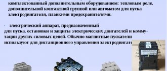
Now the devices are used mainly in production. Baggers are used to start and stop ventilation systems, elevators, conveyor drives, etc. It is used as a power element to disconnect the load in various electrical installations. The devices can also be used for current distribution in residential buildings and industrial lighting networks. The device is also indispensable for emergency connection of a backup load, that is, for switching voltage from one electrical circuit to another. Some types of devices can be used in conditions of high humidity, dust and other negative factors.
The bagger cannot protect the electrical circuit from emergency mode, so the circuit must have an automatic fuse or switch. It will protect the power system from short circuit or electrical overload.
The batch switch has only two switch positions - off, on. After a person turns the switch, movable washers come into action, which, in turn, transmit movement to the contacts. As a result, depending on the initial position, they close (current flows) or open (current stops flowing).
There are one-, two- and three-pole devices. The first two are designed for a load of 10-25 A, the permissible voltage is 220V. Three-pole devices can withstand a voltage of 380 V, while the load is slightly reduced, it should not be more than 15 A.
Open, closed and completely sealed bags are available. Open type switches do not have a protective shell. These packagers are used to switch connections at a safe voltage and only indoors. Closed devices are equipped with a housing made of plastic or metal. The terminals of these devices are protected from touch, and the device itself is perfectly protected from dirt and dust. Closed models can be installed outside the panel cabinet.
Sealed electrical appliances are enclosed in a non-flammable, shockproof, hermetically sealed plastic shell. The high level of protection allows the devices to be installed in open spaces. Some models are equipped with a transparent window through which you can monitor the status of the contacts.
The packet terminal is usually not insulated, therefore, when connected, it is energized. When replacing the device, you will need to completely turn off the current.
The popularity of packaged devices is gradually declining, but the production of such electrical appliances has not ceased. Reliability, availability, and speed of operation help baggers still remain a sought-after product.
Programmable relay EKF PRO-Relay
The main control of the operating logic is carried out by the EKF PRO-Relay programmable relay. This allows for more flexible implementation of the main functions of the control system.
In this scheme, a programmable relay controls the position of circuit breakers, ensures on-off switching of inputs, with its help time delays for operation of switches are set and changed, and diagnostic functions are performed.
In addition, if necessary, you can change the operation algorithm of the ATS circuit without extra costs and display the necessary information about the operation of the ATS to the upper level via Modbus, although this requires an additional interface module.
PRO-Design is used as software for PRO-Relay. The program can be downloaded for free from the official EKF website.
Also, to download the program you will need an ILR-ULINK cable, which will need to be purchased separately.
Algorithm of operation of the ATS circuit
The input circuit breaker QF1 powers section 1, QF2 powers section 2. In normal operation, each of the consumers connected to the ATS receives power from its section, while the section switch is in the off state.
If there is a loss of power at the first input, the second input supplies power, through a sectional switch, to section 1 and section 2, and, accordingly, vice versa, if there is a loss of power at the second input, the first input, through a sectional switch, provides power to sections 1 and 2.
The ATS operates in automatic mode after power is supplied to the programmable relay according to the established algorithm, with a 5 second delay in turning on and off when voltage is lost and appears on one of the inputs and the section switch is turned on and off.
When the voltage at input 1 disappears, the KSV1 relay contacts open, from 5 sec. with a delay, a command is given to turn off the circuit breaker QF1. After a certain period of time, the section switch turns on, provided that:
- Input machine QF1 is disabled
- There is voltage at input 2 (relay contacts KSV2 are closed)
- No signal ATS blocking
- Operating mode selection switch SA1 in auto position
When triggered, a light indication is given on the switchboard door QF1 (Input1) - off. QF2 (Input2) – on. QF3 (Sectional) – on. If the voltage at input 1 appears before the delay time of 5 seconds has expired, then the command to turn on the sectional switch is not given.
When power is restored at the first input, a command is given, with a delay, to turn off the sectional switch QF3. Then a command comes to turn on the first input machine.
When the input is restored, a light indication is given on the switchboard door QF1 (Input1) - on. QF2 (Input2) – on. QF3 (Sectional) – off.
When the voltage at input 2 disappears, the KSV2 relay contacts open, and a command is given to turn off the QF2 circuit breaker. The entire process is repeated in the same way as the first input.
If the voltage on both inputs is lost, the controller turns off.
The ATS operation is blocked when the motor drives of the circuit breakers are switched to manual mode, when QF1, QF2, QF3 are switched off when the protection is triggered by a signal from the emergency contact, or when the ATS control unit is faulty. In this case, it is possible to switch to manual control mode.
The alarm is reset (acknowledged) by the operator by turning off and on the controller's power, or by using a button on the front panel of the cabinet.
Involved programmable relay inputs and outputs
DI inputs
I1 – NO contact of the phase control relay KSV1 I2 – NO contact of the phase control relay KSV2 I3 – Switch SA1 (Manual-Auto) I4 – Button SB1 Reset error (blocking) ATS I5 – On-off status contact (Designation on the diagram OF) QF1 I6 – Emergency contact (Designation on the diagram SY) QF1 I7 – On-off contact (Designation on the diagram OF) QF2 I8 – Emergency contact (Designation on the diagram SY) QF2 I9 – On-off contact (Designation on the diagram OF) QF3 IA - Emergency contact (Designation on diagram SY) QF3
DO outputs
Q1 - Indication ATS operation in automatic mode Q2 - Indication ATS operation in manual mode Q3 - Indication ATS operation error Q4 - Disable the motor drive of the circuit breaker QF1 Q5 - Turn on the motor drive of the circuit breaker QF1 Q6 - Disable the motor drive of the circuit breaker QF2 Q7 - Turn on the motor circuit breaker drive QF2 Q8 – Disconnect the motor drive of the QF3 circuit breaker Q9 – Turn on the motor drive of the QF3 circuit breaker
AVR diagram - Download
Program - Download
Secondary circuit devices. Relay protection and system automation elements
Automatic devices, in particular relay protection, are needed where a quick response to a change in operating mode and an immediate command to turn off or turn on the corresponding circuits are required. So, for example, during a short circuit, when the current in a number of circuits increases sharply, it is necessary to immediately turn off the damaged section of the system in order to reduce the size of the destruction and not interfere with the operation of adjacent undamaged circuits. Such a command can only be given by an automatic device that responds to changes in current, direction of power and other factors and closes the control circuits of the corresponding switches.
Automatic shutdown of system elements must be selective. This means that in the event of damage at any cost, only the damaged circuit must be disconnected by the switches closest to the location of the damage. The rest of the system must not be disrupted. So, for example, when there is a short circuit at point K1 (Fig. 2), the current flows through the circuits of generators, step-up transformers, damaged and undamaged lines. However, only the damaged line on both sides must be disconnected. The station will remain connected to the system via another line.
In the event of damage to a generator or transformer, only the damaged element must be disconnected. In Fig. 2, areas of the system that must be disconnected in the event of damage are delimited by dotted lines. Each section is switched off by one or two switches. In the event of damage to the circuit breaker, two adjacent sections must be disconnected.
Fig.2. Electrical diagram of the station and network section. Dotted lines delimit sections of the station and network that are subject to disconnection in case of damage.
The selectivity of relay protection is ensured in various ways, for example, by appropriate selection of the time or current of operation of the protection of adjacent sections of the network, the use of relays that respond to the direction of power, etc.
The circuit shutdown time during a short circuit is composed of the relay protection response time and the circuit breaker shutdown time, calculated from the moment the shutdown command is given until the arc goes out at the breaker breaks.
They strive to reduce the shutdown time of the main lines of the system as much as possible so as not to disrupt the stability of the parallel operation of power plants. The shutdown time of the newest switches is two periods and the relay protection time is another 0.5 periods. The total shutdown time is therefore 2.5 periods. For distribution networks, 2.5-cycle tripping is not required. Here simpler protections and slower-acting switches are used, the cost of which is much lower. The total shutdown time is several tenths of a second or more.
Automatic restart
Automatic devices for re-closing (reclosure) of overhead lines after their protection has been disconnected are intended to quickly restore the operation of the line after a disconnection. The effectiveness of re-closing overhead lines is based on the fact that most short circuits are associated with lightning discharges and lead to overlapping of insulators along the surface. After the line is automatically turned off, the electrical strength of the air gap is quickly restored and when turned on again, the line remains in operation.
Initially, the command to restart was given manually by the person on duty at the control panel. Later, the switching operation began to be automated. Currently, automatic re-closing, single and double, is widely used. It helps to increase the reliability of power supply, especially when feeding consumers via single lines.
The total automatic re-closing time is calculated from the submission of the relay protection command to open the circuit breaker until the re-closure of its contacts. It should be as small as possible so as not to disrupt the work of consumers, but at the same time sufficient to deionize the arc gap at the point of overlap. The restart time depends on the mains voltage and the speed of the switch. In double-reclosing devices, the minimum time is selected for the first switching on from the condition of deionization of the arc gap. If the first switch-on is unsuccessful and the line is disconnected again, a second switch-on occurs with an interval of several seconds.
Automatic reserve input
Automatic devices for turning on a backup circuit (ATS) must automatically turn on a backup transformer or a backup unit to replace the one disabled by the protection, and also automatically connect the busbar section (with the corresponding load) that has lost power to an adjacent section provided with power, in order to quickly restore power supply. The break in the power supply should be relatively small, no more than 0.5 s, so that electric motors that have lost power do not have time to stop, and after power is restored they can quickly return to normal operation.
DESIGN
THO/II
A standard element of selective circuit breakers of the TNO series; TNO/II is a TN12 load switch, closed in a sealed steel tank filled with SF6 gas. The reservoir meets the leak-tight criteria of IEC 56. This means that it does not need to be refilled during normal operation of the load switch. In accordance with existing technical supervision rules for pressure equipment, the device is not subject to mandatory technical supervision of pressure equipment due to the low SF6 content in the tank. In combination with a modern and reliable remote radio monitoring system, it guarantees many years of operation without the need for technical inspections, adjustment and preservation of contacts, which is especially important on long air networks. The contacts of the load switches inside the tank are connected to bushings, allowing the installation of “self-cleaning” silicone insulators 24 (25) kV, 36 kV, with excellent hydrophobic properties, to which overhead or cable line bridges are connected, and it is also possible to attach corner adapters. For remote control, a simple and reliable electric drive with a single-spring or double-spring mechanism is used, guaranteeing instantaneous connection and disconnection of the main contacts of the load switch within 50 ms. Motor drives, which are installed in load switches and sectional switches of the TNO series, interact with all control and supervision systems through radio communication in Smart Grid systems.
Electric drives are available in two versions:
- Single-spring drive “T-1” - with a total response time of 5, 6 s,
- Double-spring drive “T-2” - interacts with fully automatic automatic reclosure, which serves to quickly disconnect damaged network fragments during a voltage-free break with a “disconnect” response time of 0.1 s.
The T-1 or T-2 motor drive is built directly into the load switch reservoir and coupled to its main operating shaft, which eliminates the possibility of tampering with the device by unauthorized persons and minimizes the possibility of erroneous alarms and non-operations. The spring mechanism, as well as the motor, have signal contacts that inform the SCADA system about the status of the device’s position, as well as an optical indicator that is visible from the ground. Each load switch is equipped with a manual actuator that allows the device to be operated manually from the ground, this actuator is designed to be mechanically locked in the armed or open position with the possibility of installing a padlock. Detailed information about load switches (sectional switches) can be found on the website www.zpue.com, as well as in the data sheet.
CHARACTERISTIC
- There is no need for regular inspection and maintenance of the main switch contacts, which greatly reduces operating costs.
- Trouble-free operation in extreme natural conditions (frost, icing, wind, forest zone)
- Low consumption and prevention of aging of all active components is caused by the use of SF6, resulting in higher reliability and excellent mechanical as well as electrical strength.
- Each load switch of the TNO series is equipped with a pressure sensor “pressostat” SF6, which monitors the pressure in the tank and is responsible for the correct operation of the load switch, and in the event of an accident, automatically cuts off the engine power supply system and at the same time prevents the execution of the “disconnect” command.
- Load switches of the TNO series are equipped with a manual emergency drive, which can perform switching operations at full rated current load in case of discharge of batteries built into the on-site telemechanics cabinet.
Design and principle of operation of a circuit breaker
Many people are interested in what a circuit breaker is for, as well as the design and principle of operation of a circuit breaker.
Today in our article we will try to answer these questions. So let's start with the first question. A circuit breaker is installed to protect cables, wires, and electrical appliances from short circuits (short circuits) and overloads.
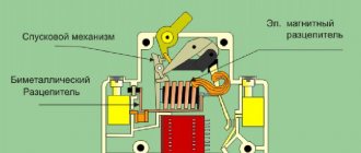
Circuit breaker device
The modular circuit breaker is externally presented in the form of a housing and a control lever, which are made of low-flammability PVC plastic. Also, with the naked eye you can determine the terminals (lower and upper) for connecting a cable or wire. are located inside the protective device housing :
• power contacts (moving and fixed), providing switching; • cocking and release mechanism, which is interconnected with the control lever; • a coil (electromagnet) and a movable core (armature), which acts as a pusher. These elements are an electromagnetic release and provide protection against short-circuit currents; • arc extinguishing chamber. This device quickly extinguishes the arc discharge that is formed when the contacts open; • bimetallic plate. This element is a thermal release and provides protection against increased load. There is also an adjusting screw, which allows you to adjust the current value at which this release should operate.
Operating principle of circuit breaker
The operation of the circuit breaker in various modes occurs according to the following principle:
1. Normal mode.
When the switch control lever is cocked, the charging and release mechanism is driven, thereby switching the power contacts. After switching, current flows from the supply wire or cable connected to the screw terminal through this clamp along the contacts, first along the fixed one and then through the movable one. Next, the current passes through the flexible connection, the electromagnet coil, again through the flexible connection and bimetallic plate, and finally through the lower screw terminal to the outgoing line that “feeds” the electrical appliance.
2. Short circuit.
In this mode, the electromagnetic release of the circuit breaker must instantly disconnect the load. The operating principle is as follows:
when the rated current flowing through the electromagnet winding is significantly exceeded, a powerful magnetic field arises, which pulls down the armature with the moving contact. The anchor, in turn, presses on the trigger lever, resulting in the load being disconnected. It should be noted that as a result of the instantaneous appearance of a magnetic field, the circuit breaker has time to turn off before undesirable consequences appear. However, during opening, an arc discharge may occur between the moving and fixed contacts. The arc moves towards the arc chute. Once on the plates, the arc splits, is drawn into the chamber and goes out. The resulting combustion products, together with excess pressure, come out through a special hole in the machine body.
The thermal release is responsible for overload protection. The operating principle of this release is as follows: when the current flowing through the bimetallic plate becomes equal to or greater than the set value, the plate heats up and gradually bends. Having reached a certain bending angle, it presses its tip on the trigger lever. Thus the machine is turned off.
It is worth noting that the thermal release, unlike the magnetic one, is slower. It takes longer to operate, but it is more accurate and easier to configure.
We talked about the design and operating principle of the circuit breaker. You can also watch our video, which shows in detail how the machine works and the principle of its operation.
Parameters of load switches, sectional switches of the TNO series
Compliance:
- PN-EN 62271-103:2011 - High-voltage distribution and control equipment. Part 103: Load switches with rated voltage above 1 kV up to and including 52 kV;
- PN-EN 62271-1:2009+A1:2011 - High-voltage distribution and control equipment. Part 1: General regulations;
- PN-EN 62271-102:2005; PN-EN 62271-102:2005/A1:2011 - High-voltage distribution and control equipment. Part 102: High Voltage AC Disconnectors and Earthing Switches;
- PN-EN 60529:2003 - Degree of protection provided by enclosures (IP code);
- PN-EN 62271-4:2014-03 - High-voltage distribution and control equipment. Part 4: Handling procedures for sulfur hexafluoride (SF6) and its mixtures;
- PN-EN 61140:2005/A1 - Protection against electric shock - general aspects for installations and equipment;
| Parameters of load switches, sectional switches of the TNO series | ||
| Type | THO-24 THO-24/II | THO-36 |
| Rated voltage Ur | 24 (25) kV | 36 kV |
| Rated frequency - number of phases fr | 50 Hz - 3 | |
| Test rated voltage at mains frequency - dry and in the rain - 1 min. Ud | ||
| - relative to ground and between phases | 50 kV | 70 kV |
| — Safe isolation gap | 60 kV | 80 kV |
| Lightning impulse test voltage (1.2/ 50 µs) Up | ||
| - relative to ground and between phases | 125 kV | 170 kV |
| — Safe isolation gap | 145 kV | 195 kV |
| Constant rated current Ir | 630 A | |
| Rated thermal current Ik | 16kA (1c) | |
| Peak rated current Ip | 40 kA | |
| Rated short-circuit making current Ima | 40 kA | |
| Rated breaking current in a low inductance circuit Iload | 630 A | |
| Rated breaking current in the ring network circuit Iloop | 630 A | |
| Rated charging interruption current of cables Icc | 60 A | |
| Arc resistance | 16k A | |
| Mechanical life (cycle - “on and off”) | 5000 | |
| Ambient temperature | — 40°C + 60°C | |
| Electric strength | E3 | |
LEGEND
THO-24-T1 is a load switch for overhead lines with a rated voltage of 24(25) kV with a standard motor drive.- THO-24-T1b - load switch for overhead lines with a rated voltage of 24 (25) kV with a standard motor drive, as well as load switch blocking indication.
- THO-24-T2 - load switch for overhead lines with a rated voltage of 24 (25) kV with a battery motor drive.
- THO/T-24-T1 - load switch for overhead lines with a rated voltage of 24 (25) kV with a motor drive without a battery.
- THO-36-T1 is a load switch for overhead lines with a rated voltage of 36 kV with a standard motor drive.
- THO-36-T2 is a load switch for overhead lines with a rated voltage of 36 kV with a battery motor drive.
- THO/T-36-T1 - load switch with earthing switch for overhead lines with a rated voltage of 36 kV with a motor drive without a battery.
- THO-24/II-T1 is a section switch with two disconnectors for overhead lines with a rated voltage of 24(25) kV with a standard motor drive.
- THO-24/II-T1b is a section switch with two disconnectors for overhead lines with a rated voltage of 24 (25) kV with a standard motor drive, as well as a load switch blocking indicator.
- THO-24/II-T2 is a section switch with two disconnectors for overhead lines with a rated voltage of 24(25) kV with a battery motor drive.
- THO/T-24/II-T1 - sectional switch with two disconnectors for overhead lines with a rated voltage of 24 (25) kV with a motor drive without a battery.
Note: * motor drive with indication of blocking setting is only possible in motor drive T1, without grounding switch.