What is NTC thermistor
An NTC thermistor means components whose resistance varies under the influence of temperature conditions. The scope of application of this radioelement depends on its properties. Basically, thermistors are needed to take measurements and control temperature indicators. Also used to detect liquid or record its absence. NTC thermistors are also found in current limiting devices. The range of their use is wide, from radio amateurs to reputable large-scale production.
Among the tasks assigned to NTC thermistors, temperature control is considered important. Therefore, it is difficult for developers of both complex industrial equipment and simple household appliances to do without these elements.
The modern market offers a large selection of NTC thermistors from manufacturers representing different countries of the world. This element was first invented back in 1930. It was introduced by scientist Samuel Reuben.
Encapsulated NTC Thermistors
Fiberglass NTC Thermistor These are NTC temperature sensors sealed in an airtight glass bubble. They are designed for use at temperatures above 150°C or for PCB mounting where durability is required. Encapsulating the thermistor in glass increases the stability of the sensor as well as protecting the sensor from the environment. They are manufactured by hermetically sealing NTC type resistors into a glass container. Typical sizes range from 0.4 to 10 mm in diameter.
Typical Applications
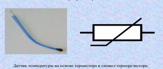
NTC thermistors with encapsulated coating.
NTC thermistors are used in a wide range of applications. They are used for temperature measurement, control temperature and temperature compensation. They can also be used to detect the absence or presence of liquid, as current limiting devices in power circuits, temperature monitoring in automotive components, and many others. NTC sensors can be divided into three groups, depending on the electrical characteristics used in units and devices.
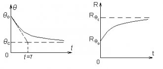
Resistance-temperature characteristic
Typical applications.
Applications based on the resistance-time characteristic include temperature measurement, control and compensation. This also includes situations in which an NTC thermistor is used, so that the temperature of the NTC temperature sensor is related to some other physical phenomena. This group of units requires the thermistor to operate under zero power conditions, which means that the current passing through it is kept as low as possible to avoid heating the probe.
Current time characteristic
Devices based on the current time characteristic are: time delay, inrush current limiting, surge suppression and much more. These characteristics are related to the heat capacity and dissipation constant of the NTC thermistor used. The circuit typically relies on an NTC thermistor, heating up due to the current passing through it. At some point this will cause some kind of change in the circuit, depending on the device in which it is used.
Voltage characteristic
Devices based on the voltage and current characteristics of the thermistor typically involve changes in environmental conditions or circuit changes that result in changes in the operating point on a given curve in the circuit.
Depending on the application, this can be used for current limiting, temperature compensation or temperature measurement. NTS thermistor symbol.
NTC Thermistor Range
The main classification by type is related to the production process that was used in the manufacture of the radio element:
- beaded;
- disk and chip;
- in a glass shell.
The bead thermistor is specially baked into a housing part made of ceramic material. The component itself is an alloy of platinum in lead wire. This type is distinguished by its fast response. The thermistor is able to function smoothly at high temperatures.
Chip and disk thermistors are usually made of metallized contacts. They have the ability to withstand high currents.
Thermistors equipped with a glass shell can operate at temperatures of +150 degrees and above. These are sealed radioelements, which are sealed in a glass vial that does not allow air flow. They are not exposed to climatic conditions, so they can be installed on open surfaces of boards.
All of the above types have good mechanical strength of the housing, high sensitivity and are reliable in practice, which makes it possible to use them in motors, fluorescent lamps, transformers, electric motors with a direct current not exceeding 20 A, household, industrial and auto electronics, mobile devices, modern monitors with LCD and HDD characteristics.
Groups of thermistors, their characteristics
All NTC thermistors are divided into groups depending on the temperature they can withstand. This parameter explains in which mode the device is capable of operating, and where it simply cannot cope with its functional responsibilities.
Thermistors are:
- low temperature (up to 170K);
- medium temperature (170–510K);
- high temperature (900–1300K).
Thermistors are also divided into thermistors and posistors. The former have a negative temperature coefficient (TCC), while the latter have a positive temperature coefficient. Another variety is known - a combined component. For example, an NTC thermistor, which has indirect heating. The device body contains a sensor equipped with a heating element. It sets the temperature of the thermistor and the initial current resistance. These radioelements are found in practice in the form of variable resistors that control the voltage applied to the heating sensor.
Classification depending on the operating principle
Based on the principle of operation, thermistors are divided into:
- contact;
- contactless.
The first category usually includes bimetallic elements, various temperature sensors, and thermocouples. If we are talking about a non-contact operating principle, then these are sensors with an infrared option. They are capable of detecting infrared radiation and optical rays emitted by liquids and gases.
Voltage characteristic
Devices based on the voltage and current characteristics of the thermistor typically involve changes in environmental conditions or circuit changes that result in changes in the operating point on a given curve in the circuit. Depending on the application, this can be used for current limiting, temperature compensation or temperature measurement.
Identical thermistors
Designations and explanation of markings
There are several types of markings. For example, from letters or different colors, stripes or other images applied to the surface of the thermistor. It all depends on the manufacturer and the specific type of elements. An approximate notation system is shown in the picture below. There are so many options that even an experienced master cannot always decipher them correctly. In this case, it is better to rely on the technical data that is on the thermistor manufacturer’s website in the description of a specific element.
Let's look at an example - an NTC thermistor marked 10 D-9. The first digit “10” indicates that 10 ohms at 25 degrees Celsius constitutes the resistance of the sensor. Its diameter is 9 mm. The higher this value is, the higher the power it dissipates. To better understand color markings, you should use a table or look at the description of characteristics in the reference book. All manufacturers clarify this information for their product lines.
The shape of a semiconductor can be different: thin pipes, large washers, plates of different thicknesses and small elements of different types. There are even parts whose dimensions are measured in several microns. The picture below shows an assortment of semiconductors that are more common than others on the modern market.
Calculation of table of values
I present to your attention a script for online calculation of a table of ADC values.
The values are calculated either based on two values of temperature and resistance, or entered in a list, or one of the preloaded R/T characteristics is used. The R/T characteristics of thermistors from Siemens/EPCOS are currently loaded. Select the appropriate one from the list.
The loaded characteristics are given with a step of 5°C; when choosing a smaller grid step, the values are obtained by interpolation using the formulas [1]
and
[2]
the two closest values from the table.
When the table is built, the example source code below it is automatically updated accordingly.
Attention!
Since thermistor parameters are largely nonlinear, calculations based on two resistance values, or a value and a coefficient, will be very approximate. The calculated temperature value when measuring high or low temperatures in this case may differ significantly (by tens of degrees) from the actual one.
To find out the appropriate type of R/T characteristic for your thermistor, download the documentation provided by the manufacturer.
A summary table for some Siemens/Epcos thermistor models is shown below. Click on the R/T characteristics code to upload the parameters into the form below:
| Code | Resistance at 25°C, kOhm | R/T characteristic | B25/100, K | |
| B57891S , 4.5mm output (datasheet, pdf) | ||||
| B57891S0222+008 | 2,2 | 1008 | 3560 | |
| B57891S0502+008 | 5 | 2003 | 3980 | |
| B57891S0103+008 | 10 | 4901 | 3950 | |
| B57891S0203+008 | 20 | 2904 | 4300 | |
| B57891S0104+008 | 100 | 4003 | 4450 | |
| B57891M , 3.5mm output (datasheet, pdf) | ||||
| B57891M0102+000 | 1 | 1009 | 3930 | |
| B57891M0152+000 | 1,5 | 1008 | 3560 | |
| B57891M0222+000 | 2,2 | 1013 | 3900 | |
| B57891M0332+000 | 3,3 | 2003 | 3980 | |
| B57891M0472+000 | 4,7 | 2003 | 3980 | |
| B57891M0682+000 | 6,8 | 2003 | 3980 | |
| B57891M0103+000 | 10 | 4901 | 3950 | |
| B57891M0153+000 | 15 | 2004 | 4100 | |
| B57891M0223+000 | 22 | 2904 | 4300 | |
| B57891M0333+000 | 33 | 2904 | 4300 | |
| B57891M0473+000 | 47 | 4012 | 4355 | |
| B57891M0683+000 | 68 | 4012 | 4355 | |
| B57891M0104+000 | 100 | 4003 | 4450 | |
| B57891M0154+000 | 150 | 2005 | 4600 | |
| B57891M0224+000 | 220 | 2005 | 4600 | |
| B57891M0334+000 | 330 | 2007 | 4830 | |
| B57891M0474+000 | 470 | 2006 | 5000 | |
| B57164K , 5.5mm output (datasheet, pdf) | ||||
| B57164K0471+000 | 0,47 | 1306 | 3450 | |
| B57164K0681+000 | 0,68 | 1307 | 3560 | |
| B57164K0102+000 | 1 | 1011 | 3730 | |
| B57164K0152+000 | 1,5 | 1013 | 3900 | |
| B57164K0222+000 | 2,2 | 1013 | 3900 | |
| B57164K0332+000 | 3,3 | 4001 | 3950 | |
| B57164K0472+000 | 4,7 | 4001 | 3950 | |
| B57164K0682+000 | 6,8 | 2903 | 4200 | |
| B57164K0103+000 | 10 | 2904 | 4300 | |
| B57164K0153+000 | 15 | 1014 | 4250 | |
| B57164K0223+000 | 22 | 1012 | 4300 | |
| B57164K0333+000 | 33 | 1012 | 4300 | |
| B57164K0473+000 | 47 | 4003 | 4450 | |
| B57164K0683+000 | 68 | 2005 | 4600 | |
| B57164K0104+000 | 100 | 2005 | 4600 | |
| B57164K0154+000 | 150 | 2005 | 4600 | |
| B57164K0224+000 | 220 | 2007 | 4830 | |
| B57164K0334+000 | 330 | 2006 | 5000 | |
| B57164K0474+000 | 470 | 2006 | 5000 | |
| B57540G , output, glass “drop” 0.8mm (datasheet, pdf) | ||||
| B57540G0502+000, +002 | 5 | 8402 | 3497 | |
| B57540G1103+000, +002 | 10 | 8307 | 3492 | |
| B57540G1103+005, +007 | 10 | 7003 | 3625 | |
| B57540G0203+000, +002 | 20 | 8415 | 4006 | |
| B57540G1303+005, +007 | 30 | 7002 | 3988 | |
| B57540G0503+000, +002 | 50 | 8403 | 4006 | |
| B57540G1104+000, +002 | 100 | 8304 | 4092 | |
| B57540G0234+000, +002 | 230 | 8405 | 4264 | |
| B57540G0145+000, +002 | 1400 | 8406 | 4581 | |
| B57551G , output, glass “drop” 1.8mm (datasheet, pdf) | ||||
| B57551G0202+000, +002 | 2 | 8401 | 3436 | |
| B57551G1103+000, +002 | 10 | 8307 | 3492 | |
| B57551G1103+005, +007 | 10 | 7003 | 3625 | |
| B57551G1303+005, +007 | 30 | 7002 | 3988 | |
| B57551G1104+000, +002 | 100 | 8304 | 4092 | |
| B57621С5 , SMD 3.2x1.6mm (datasheet, pdf) | ||||
| B57621C5102+062 | 1,0 | 3206 | 3450 | |
| B57621C5472+062 | 4,7 | 1309 | 3520 | |
| B57621C5103+062 | 10 | 1010 | 3530 | |
| B57621C5153+062 | 15 | 1008 | 3560 | |
| B57621С0 , SMD 3.2x1.6mm (datasheet, pdf) | ||||
| B57621C0222+062 | 2,2 | 1308 | 3060 | |
| B57621C0332+062 | 3,3 | 1309 | 3520 | |
| B57621C0472+062 | 4,7 | 1309 | 3520 | |
| B57621C0103+062 | 10 | 1010 | 3530 | |
| B57621C0153+062 | 15 | 1008 | 3560 | |
| B57621C0223+062 | 22 | 1008 | 3560 | |
| B57621C0333+062 | 33 | 2003 | 3980 | |
| B57621C0473+062 | 47 | 2001 | 3920 | |
| B57621C0683+062 | 68 | 2001 | 3920 | |
| B57621C0104+062 | 100 | 4901 | 3950 | |
| B57621C0154+162 | 150 | 2903 | 4200 | |
| B57621C0224+062 | 220 | 2903 | 4200 | |
| B57621C0334+062 | 330 | 1014 | 4250 | |
| B57621C0474+062 | 470 | 1014 | 4250 | |
| B57703M , output 10mm, with “ear” 8.5x3.7mm (datasheet, pdf) | ||||
| B57703M0502G040 | 5 | 8016 | 3988 | |
| B57703M0103G040 | 10 | 8016 | 3988 | |
| B57703M0303G040 | 30 | 8018 | 3964 | |
Form for online calculation of ADC values
| Data for the table | *Due to the nonlinearity of the thermistor parameters, temperature calculation based on a table built from two points will be rough and the resulting value may differ by tens of degrees from the actual one when measuring high and low temperatures. For accurate measurements over a wide range, select one of the preloaded R/T characteristics to match your thermistor, or enter a list of R/R1 values manually. |
| T1 | °C |
| R1, resistance at T1 | kilo ohm |
| T2 | °C |
| R2, resistance at T2 | kilo ohm |
| Data for the table: R/R1 starting from T2, with the selected grid spacing. The value separator is a comma. | |
| BT1/T2 | K |
| Thermistor connection circuit | |
| Resistor value RA | kilo ohm |
| Resistor value RB | kilo ohm |
| ADC capacity | |
| ADC result multiplier | |
| U0, input voltage | IN |
| Uref, ADC reference voltage | IN |
| Calculate with | °C to °C |
| Grid pitch | |
| T,°С | R/R1 | R, kiloOhm | U,V | I, µA | P,mW | U/Uref | ADC | E,°С |
Explanations for the table:
bold
The values of R/R1 and R obtained on the basis of the tables are highlighted. Normal font indicates values obtained by interpolation or extrapolation using formulas.
ADC
– rounded value at the ADC output, taking into account the multiplier. Values outside the ADC measurement limit are not displayed.
I, µA
- current in the circuit.
P,mW
— power dissipated by the thermistor.
E
– heuristic assessment of the possible error in the calculated temperature caused by the use of linear interpolation of table values and the limited accuracy of the ADC. Allows you to select parameters and switching circuit in such a way that the error in the range of measured values is minimal. This estimate does not take into account possible noise that occurs on the ADC, as well as the error caused by heating of the thermistor due to current flow. The error can be reduced by choosing a smaller table step, using an ADC with a larger capacity, or by averaging a larger number of measurements, as well as by selecting resistance values in the circuit.
Code corresponding to the table
#include #include // Temperature value returned if the sum of ADC results is greater than the first value of the table #define TEMPERATURE_UNDER 0 // Temperature value returned if the sum of ADC results is less than the last value of the table #define TEMPERATURE_OVER 0 // Temperature value corresponding to the first value of the table #define TEMPERATURE_TABLE_START 0 // Table step #define TEMPERATURE_TABLE_STEP 50 // The type of each element in the table, if the sum is within 16 bits - uint16_t, otherwise - uint32_t typedef uint16_t temperature_table_entry_type;
// Table index type. If the table has more than 256 elements, then uint16_t, otherwise - uint8_t typedef uint8_t temperature_table_index_type; // Access method to a table element, must correspond to temperature_table_entry_type #define TEMPERATURE_TABLE_READ(i) pgm_read_word(&termo_table ) /* Table of the total ADC value depending on temperature. From the largest value to the smallest The following parameters are used to build the table: */ const temperature_table_entry_type termo_table[] PROGMEM = { 0 // Click “Build table” on the form above to fill this array }; // The function calculates the temperature value in tenths of degrees Celsius // depending on the total ADC value. int16_t calc_temperature(temperature_table_entry_type adcsum) { temperature_table_index_type l = 0; temperature_table_index_type r = (sizeof(termo_table) / sizeof(termo_table[0])) - 1; temperature_table_entry_type thigh = TEMPERATURE_TABLE_READ(r); // Check for overruns and boundary values if (adcsum <= thigh) { #ifdef TEMPERATURE_UNDER if (adcsum < thigh) return TEMPERATURE_UNDER; #endif return TEMPERATURE_TABLE_STEP * r + TEMPERATURE_TABLE_START; } temperature_table_entry_type tlow = TEMPERATURE_TABLE_READ(0); if (adcsum >= tlow) { #ifdef TEMPERATURE_OVER if (adcsum > tlow) return TEMPERATURE_OVER; #endif return TEMPERATURE_TABLE_START; } // Binary search through the table while ((r - l) > 1) { temperature_table_index_type m = (l + r) >> 1; temperature_table_entry_type mid = TEMPERATURE_TABLE_READ(m); if (adcsum > mid) { r = m; } else { l = m; } } temperature_table_entry_type vl = TEMPERATURE_TABLE_READ(l); if (adcsum >= vl) { return l * TEMPERATURE_TABLE_STEP + TEMPERATURE_TABLE_START; } temperature_table_entry_type vr = TEMPERATURE_TABLE_READ(r); temperature_table_entry_type vd = vl - vr; int16_t res = TEMPERATURE_TABLE_START + r * TEMPERATURE_TABLE_STEP; if (vd) { // Linear interpolation res -= ((TEMPERATURE_TABLE_STEP * (int32_t)(adcsum - vr) + (vd >> 1)) / vd); } return res; }
Main characteristics of thermistors
It is important to pay attention to the characteristics of NTC thermistors. They may change for a number of reasons: manufacturer, type and material used. First of all, the buyer should study the size. It is necessary that the element fits in size, that is, fits on the board during installation.
The following important points:
- resistance RT;
- time constant;
- dissipation coefficient.
These are the main points to consider when purchasing a part.
Heating characteristics
There are 2 types of thermistors, depending on the heating method underlying their operating principle:
- indirect;
- straight.
With indirect heating, the temperature of the thermistor will change under the influence of elements placed next to it.
When direct, it also changes, but only under the influence of the surrounding air or the current that passes through the element. This is the main difference.
A program for calculating the temperature on a thermistor
To calculate the temperature value, use the Steinhart-Hart formula:
The equation has parameters A, B and C, which must be taken from the specification for the sensor. Since we do not need great accuracy, we can use a modified equation (B-equation):
In this equation, only parameter B remains unknown, which for an NTC thermistor is equal to 3950. The remaining parameters are already known to us:
- T0 is the room temperature in Kelvin, for which the thermistor rating is indicated; T0 = 25 + 273.15;
- T is the desired temperature, in Kelvin;
- R is the measured resistance of the thermistor in Ohms;
- R0 is the nominal resistance of the thermistor in Ohms.
Let's modify the program for Arduino by adding temperature calculation:
#define B 3950 // B-factor #define SERIAL_R 102000 // series resistor resistance, 102 kOhm #define THERMISTOR_R 100000 // nominal thermistor resistance, 100 kOhm #define NOMINAL_T 25 // nominal temperature (at which TR = 100 kOhm) const byte tempPin = A0; void setup() { Serial.begin( 9600 ); pinMode(tempPin, INPUT); } void loop() { int t = analogRead( tempPin ); float tr = 1023.0 / t - 1; tr = SERIAL_R / tr; Serial.print("R="); Serial.print(tr); Serial.print(“, t=”); float steinhart; steinhart = tr/THERMISTOR_R; // (R/Ro) steinhart = log(steinhart); // ln(R/Ro) steinhart /= B; // 1/B * ln(R/Ro) steinhart += 1.0 / (NOMINAL_T + 273.15); // + (1/To) steinhart = 1.0 / steinhart; // Invert steinhart -= 273.15; Serial.println(steinhart); delay(100); }
Result:
Already better! The program shows us the temperature in degrees Celsius. As expected, it is slightly below 25 C°.
Checking the serviceability of the part
First you need to set the multimeter to a mode that will allow you to measure resistance. After this, connect the probes to the legs of the radio element. Fix the resistance and bring the soldering iron to the element. It is better to record resistance indicators on paper. The soldering iron must be preheated. Carry out control measurements. If the resistance drops, then the thermistor is working correctly. If it is a posistor, then the resistance should increase.
For example, when testing the NTC MF 72 thermistor, the resistance is 6.9 Ohms, but when changing the temperature using a soldering iron, it drops to 2 Ohms. The test result is correct.
When the resistance remains the same or changes suddenly, you can assume that the NTC thermistor has failed. I would like to additionally note that such checks are highly discouraged because they are crude. If the goal is to accurately control the thermistor, you need to check its temperature, then the resistance. The data must be compared with the parameters indicated by the manufacturer in the specifications.
NTC thermistor
What are NTC thermistors?
The thermistor built into the stainless steel probe is a "negative temperature coefficient". NTC thermistors are negative temperature coefficient resistors, which means the resistance decreases as temperature increases. They are mainly used as resistive temperature sensors and current limiting devices. The temperature sensitivity coefficient is approximately five times greater than silicon temperature sensors (silistors) and approximately ten times greater than resistance temperature sensors (RTDs). NTC sensors are typically used between -55°C and 200°C.
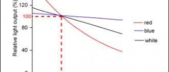
ntc thermistor characteristics.
The nonlinearity of the relationship between resistance and temperature exhibited by NTC resistors has been a major problem when using analog circuits to accurately measure temperature, but the rapid development of digital circuits has solved this problem, allowing precise values to be calculated by interpolating lookup tables or by solving equations that approximate the typical NTC curve.
NTC benefits
Thermistors are in much greater demand than posistors. They have a number of advantages. These are elements that can be used reliably for a long time without worrying about their failure, even despite extreme environmental conditions. Another plus is its compact dimensions.
The packaging is so convenient that the use of radioelements is possible in a small area or in a limited space; they do not require much space on the board. Another advantage is fast response time. They react to changes in temperature if there is a need for feedback. Cost-effectiveness indicators are no less important.
The master can count on an inexpensive price, as well as simple installation. But even such an advantageous element is not without its drawbacks. It lies in the fact that in the conditions of modern production there is no possibility of producing it in mass quantities, maintaining the same characteristics. The parameters are very different. This applies to cases where elements are produced in one batch. For this reason, it is necessary to re-configure the equipment.
Popular thermistors
As mentioned above, many forms and types of thermistors are known today. Often there are parts in phenol with a special coloring. It is impossible to say unequivocally and accurately which type or form is the most popular. The shape depends on what task is assigned to the thermistor; its characteristics also matter.
Bead thermistors are considered the optimal solution for installation in a device. The disk version is more appropriate for surfaces with optical properties. If we talk about the chip form, installation is recommended on a printed circuit board. When determining this characteristic, the master should take into account how tight the contact between the surface and the device should be. Whatever the type of thermistor, it is important that a thermally conductive paste or epoxy adhesive that does not have electrical conductivity properties is used to connect it to the surface.
If the task is to replace the thermistor, you should use a similar element, having studied its characteristics in the reference book or technical documentation. The technician can replace the thermistor with a regular wirewound resistor, but only if he has had similar experience in the past, and if there were no problems with the operation of the device the previous time. Be sure to check the optionality conditions of the element both in time and voltage. It is also important to understand whether the new resistor fully performs the functions of a thermistor.
Connecting a thermistor to Arduino
To measure the resistance of the thermistor, we connect it as the lower arm of a voltage divider. We will connect the middle point of the divider to the Arduino analog input - A0. A similar method was used in the lesson about the photoresistor.
We talked in detail about the analog inputs of Arduino in the lesson: Analog-to-digital conversions - ADC
Schematic diagram
Layout appearance
What resistance should the resistor have in the upper arm of the divider? As a rule, a resistor is used with a resistance that matches the value of the thermistor. In our lesson we use a resistor with R1 = 102 kOhm, it can be easily obtained by connecting two 51 kOhm resistors in series.
More about the scope
All thermistors can be used in a fairly wide range of applications. If we are talking about a more expensive device, this allows it to be made part of complex production equipment or used as a fuse. Specialists connect thermistors to relays. This allows the system to turn off automatically as soon as it detects overheating. In terms of price, thermistors are much less expensive than other components. This explains the high demand for them in the market. They are used both in everyday life and in production.
With proper configuration and installation of the thermistor, it can become an element for checking the temperature conditions outdoors or indoors. You can use it to track any changes. Of course, we are not talking about such accurate measurements as is required in production areas. A step of one degree will be enough. The part is also often used in the engine protection system against overheating. In this case, the specialist connects it to the relay. If a heating hazard occurs that violates all acceptable safety precautions, the engine is switched off. If you have experience, you can include a thermistor in the on-board PC system. This allows you to track indicators on the monitor, which is a very convenient solution in practice.
All thermistors are produced in housings with protective properties, which eliminates the influence of moisture on them. This has a positive effect on the service life of the element. If a specialist selects the thermistor correctly, he can count on long-term use of the element and the equipment in which it will be installed.
Program for calculating thermistor resistance
The first program we will write will calculate the resistance of the thermistor in ohms.
#define SERIAL_R 102000 // resistance of the serial resistor, 102 kOhm const byte tempPin = A0; void setup() { Serial.begin( 9600 ); pinMode(tempPin, INPUT); } void loop() { int t = analogRead( tempPin ); float tr = 1023.0 / t - 1; tr = SERIAL_R / tr; Serial.println(tr); delay(100); }
Result of the program:
You can notice that the measured resistance of the thermistor is less than 100 kOhm, which means the ambient temperature is below 25 C°. The next step is to calculate the temperature in degrees Celsius.