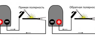
Designation of the current source on the diagrams (option)
Current source
(in the theory of electrical circuits) - an element, a two-terminal network, the current strength through which does not depend on the voltage at its terminals (poles).
current generator
and
ideal current source
are also used .
The current source is used as a simple model of some real sources
electrical energy or as part of more complex models of real sources containing other electrical elements. It should be noted that the electrical characteristics of real sources may be close to the properties of a current source or its opposite - a voltage source.
In electrical engineering, a current source is any source of electrical energy.
Properties[ | ]
Ideal current source[ | ]
The strength of the current flowing through an ideal current source is always the same by definition:
I = const {\displaystyle I={\text{const}}}
The voltage at the terminals of an ideal current source ( not to be confused with a real source!
) depends only on the resistance R {\displaystyle R} of the load connected to it:
U = I ⋅ R {\displaystyle U=I\cdot R}
Power supplied by the current source to the load:
P = I 2 ⋅ R {\displaystyle P=I^{2}\cdot R}
Since the current through an ideal current source is always the same, the voltage at its terminals and the power transmitted by it to the load increase with increasing load resistance, reaching infinite values in the limit.
Real source[ | ]
In a linear approximation, any real
a current source (not to be confused with the current source described above - a model!) or another two-terminal network can be represented in the form of a model containing at least two elements: an ideal source and internal resistance (conductivity).
One of the two simplest models - Thevenin's model - contains an EMF source connected in series with a resistance, and the other, opposite to it, Norton's model, contains a current source connected in parallel with conductivity (that is, an ideal resistor, the properties of which are usually characterized by the conductivity value). Accordingly, a real
source in a linear approximation can be described using two parameters: EMF E {\displaystyle {\mathcal {E}}} of the voltage source (or current I {\displaystyle I} of the current source) and internal resistance r {\displaystyle r} (or internal conductivity y = 1 / r {\displaystyle y=1/r} ).
It can be shown that a real current source with internal resistance r {\displaystyle r} is equivalent to a real emf source having internal resistance r {\displaystyle r} and emf E = I ⋅ r {\displaystyle {\mathcal {E}}=I\ cdot r} .
The voltage at the terminals of a real current source is
U out = IR ⋅ r R + r = IR 1 + R / r. {\displaystyle U_{\text{out}}=I{\frac {R\cdot r}{R+r}}=I{\frac {R}{1+R/r}}.}
The current in the circuit is equal to
I out = I r R + r = I 1 1 + R / r. {\displaystyle I_{\text{out}}=I{\frac {r}{R+r}}=I{\frac {1}{1+R/r}}.}
The power supplied by a real current source to the network is equal to
P out = I 2 R ( 1 + R / r ) 2 . {\displaystyle P_{\text{out}}=I^{2}{\frac {R}{\left(1+R/r\right)^{2}}}.}
Real current generators have various limitations (for example, on the voltage at its output), as well as nonlinear dependencies on external conditions. In particular, real current generators create electric current only in a certain voltage range, the upper threshold of which depends on the supply voltage of the source. Thus, real current sources have load limitations.
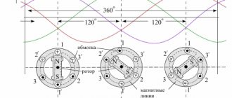
The operating principle of any electric generator
The operating principle of any electric generator is based on the phenomenon of electromagnetic induction. Electromagnetic induction converts the mechanical energy of the engine (rotation0 into electrical energy. The principle of magnetic induction: if a frame rotates uniformly in a uniform magnetic field B, then a variable E.M.F. appears in it, the frequency of which is equal to the frequency of rotation of the frame. Will we rotate frame in a magnetic field, or a magnetic field around the frame, or a magnetic field inside the frame, the result will be the same - E.M.F., changing according to a harmonic law.
Now let's talk about asynchronous and synchronous generators in more detail.
Examples[ | ]
The current source is an inductor through which current flowed from an external source for some time ( t ≪ L / R {\displaystyle t\ll L/R} ) after the source was turned off. This explains the sparking of the contacts when the inductive load is quickly turned off: the desire to maintain current with a sharp increase in resistance (the appearance of an air gap) leads to a sharp increase in the voltage between the contacts and to breakdown of the gap.
The secondary winding of a current transformer, the primary winding of which is connected in series with a powerful alternating current line, can be considered as an almost ideal source of alternating current. Therefore, opening the secondary circuit of the current transformer is unacceptable. Instead, if recommutation is necessary in the secondary winding circuit (without disconnecting the line), this winding is first bypassed.
Alternators
Alternating current generators are designed and operate on the principle of a simple experimental alternator. These devices consist of the following elements:
- Rotor. It is a metal core placed on the main shaft of the generator. The rotor may or may not have a winding wire. It all depends on the type of device. The rotor is the moving part of the device. It is driven by a drive mechanism (engine, turbine, blades).
- Stator. The fixed part, which is also equipped with a copper winding. The winding is placed in specially cut grooves and has insulation between the metal casing and the wire itself.
- Slip rings with brushes or commutator. These elements are used to apply constant voltage to the windings to initially excite them. The collector is also used as a rectifier. It prevents directional changes.
This generator works according to the following principle:
- The excitation current is supplied to the stator winding, which is a permanent magnet. Next, a magnetic field is formed.
- The rotating rotor with winding also becomes a permanent magnet. Because of this, an EMF is created between the stator and the rotor.
- During rotation, the magnetic field intersects, resulting in the formation of alternating current.
- Current flows through the switching brush assembly into the connected circuit.
Alternating current generators come in many varieties. They differ in:
- Classifications. Can be synchronous or asynchronous. Synchronous are dependent on the rotation speed and the frequency of the alternating EMF. Such generators are easy to identify visually. Their movable rotor has a winding. Asynchronous ones do not have a winding on the rotor. They do not depend on rotation speed, are more resistant to changes in speed and are not subject to rapid heating during short circuits.
- According to the method of arousal. There are 4 main types: from an external power source; self-exciting; from a more powerful generator that works in conjunction with the main one; from a permanent magnet.
- By number of phases. There are single-, two- and three-phase models. The most common are three-phase types of devices.
- According to the method of connecting the stator winding. There are 2 main schemes - a triangle and a star. The difference between these two schemes is the way they are connected. When a star is used, all ends of the windings are connected at one point. “Triangle” - provides for a serial connection of all ends of the winding.
- By design. Variable type generators can be: with a fixed stator or with a fixed rotor.
- According to the method of energy conversion.
Also, generators may differ in the method of operation. They can be stationary or portable.
Application[ | ]
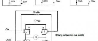
Figure 2. Current mirror type current generator assembled on bipolar transistors
Current sources are widely used in analog circuitry, for example, to power measuring bridges, to power stages of differential amplifiers, in particular operational amplifiers.
The concept of a current generator is used to represent real electronic components in the form of equivalent circuits. To describe the active elements for them, equivalent circuits containing controlled generators are introduced:
- Voltage controlled current source (VCS). Mainly used for field-effect transistors and vacuum tubes.
- Current controlled current source (CCU). Typically used for bipolar transistors.
In the current mirror circuit (Figure 2), the load current in the right branch is set equal to the reference current in the left branch, so that with respect to the load R2
this circuit acts as a current source.
Manufacturing companies
Since terminals are a necessary element of any electronics, such a product is in high demand, and many companies produce it.
The main terminal manufacturing companies include:
- Weidmüller . One of the largest manufacturers of automation systems and industrial connections. Today, terminals from Weidmuller are known in many countries around the world, including Russia. The company is a large international holding company and has representative offices in more than eighty countries around the world.
- Phoenix Contact . The group of companies includes twelve enterprises and has its own production structures. The company is distinguished by the production of high-quality terminals for the high price segment. This manufacturer has offices in approximately thirty countries around the world.
- WAGO Kontakttechnik . One of the largest German manufacturers, offering terminals in many countries around the world. He is the inventor of the Cage Clamp, which has become the reason for its popularity throughout the world. It has its own factories, which are located in different countries of the world, including in Europe. The manufacturer offers high quality products in the premium segment.
There are also other companies producing terminals and terminal blocks, but the three companies presented above are enough to choose the right device. It is wise to give preference to products from well-known manufacturers.
Notation[ | ]
There are various options for designating a current source. The most common designations are (a) and (b). Option (c) is established by GOST[1] and IEC[2]. The arrow in the circle indicates the positive direction of the current in the circuit at the source output. Options (d) and (e) are found in foreign literature. When choosing a designation, you need to be careful and use explanations to avoid confusion with voltage sources.
Figure 3. Current source symbols on diagrams
Technical requirements for terminal clamps
Before selecting terminals, you need to pay attention to the requirements for these devices. They must have high safety, since the terminals involve working with electrical networks.
Let's look at the list of these requirements:
- The terminals must be made of high quality plastic that can withstand high temperatures. Typically, devices made from liquid crystal polymers are chosen.
- The plastic must have fire-resistant properties. Typically, plastic containing polyamide is chosen.
- The terminal clamp must be made of materials that can withstand high temperatures and do not corrode. Typically, clamps made of stainless materials are chosen.
Chemical current source
Chemical DC power supplies are a family of devices and apparatus that produce voltage at their terminals as a result of internal chemical processes of oxidation or galvanization. Their work is based on the reactions of chemical substances, which, when interacting with each other, produce a constant electric current.
For your information. Processes occurring in chemical sources (CHS) occur without thermal or mechanical influences. This sets them apart among devices that generate voltages of constant polarity.
Some types of chemical current sources
Terms and definitions are described in detail in GOST R IEC 60050-482-2011, which came into effect on July 1, 2012. It abbreviates chemical current sources - HIT.
The division by type of chemical insulation is carried out in the following gradation:
- primary;
- fuel;
- batteries.
This distinction is made by the mode of action of the source.
Chemical current sources
Single use items are primary sources. They contain a finite supply of reagents that will react and stop producing energy at the end of the process. These are various AA batteries.
Fuel HITs are capable of operating continuously, but require the supply of a new dose of substances and the removal of waste products. Essentially, this is a galvanic cell into which fuel and oxidizer are supplied separately and react at two electrodes. The fuel dissolves in the electrolyte and cathodic oxidation occurs. It is a virtually precision laboratory process.
Fuel cell operation diagram
Secondary cells that can be used many times after being recharged or recharged are called batteries. If current is connected to such devices, they are regenerated again and accumulate energy. They have found the widest application in powering mobile devices and mechanisms.
Battery power source