Servo for Arduino
A servo drive is a type of drive that can precisely control motion parameters. In other words, it is a motor that can rotate its shaft through a specific angle or maintain continuous rotation at a precise period.
The servo drive's operating circuit is based on the use of feedback (a closed circuit in which the input and output signals are not matched). The servo drive can be any type of mechanical drive, which includes a sensor and a control unit that automatically maintains all the parameters set on the sensor. The servo drive consists of a motor, a position sensor and a control system. The main task of such devices is implementation in the field of servomechanisms. Also, servo drives are often used in such areas as material processing, production of transport equipment, wood processing, metal sheet production, construction materials production and others.
In Arduino robotics projects, servo is often used for simple mechanical actions:
- Rotate the rangefinder or other sensors to a certain angle to measure distance in a narrow field of view of the robot.
- Take a small step with your foot, move your limb or head.
- To create robotic manipulators.
- To implement the steering mechanism.
- Open or close a door, flap or other object.
Of course, the scope of application of servo in real projects is much wider, but the examples given are the most popular schemes.
Scheme and types of servos
The operating principle of a servo drive is based on feedback from one or more system signals. The output indicator is fed to the input, where its value is compared with the setting action and the necessary actions are performed - for example, the engine is turned off. The simplest implementation option is a variable resistor, which is controlled by the shaft - when the parameters of the resistor change, the parameters of the current supplying the motor change.
In real servos, the control mechanism is much more complex and uses built-in controller chips. Depending on the type of feedback mechanism used, analog and digital servos are distinguished. The former use something similar to a potentiometer, the latter use controllers.
The entire servo control circuit is located inside the housing, control signals and power are supplied, as a rule, through three wires: ground, supply voltage and control signal.
Continuous rotation servo 360, 180 and 270 degrees
There are two main types of servomotors - with continuous rotation and with a fixed angle (most often, 180 or 270 degrees). The difference between servo limited rotation lies in the mechanical elements of the design that can block the movement of the shaft outside the angles specified by the parameters. Having reached an angle of 180, the shaft will affect the limiter, and it will give a command to turn off the motor. Continuous rotation servomotors do not have such limiters.
Servo gear materials
For most servos, the connecting link between the shaft and external elements is a gear, so it is very important what material it is made of. There are two most affordable options: metal or plastic gears. In more expensive models you can find elements made of carbon fiber and even titanium.
Plastic options are naturally cheaper, easier to manufacture, and are often used in inexpensive servos. For educational projects where the servo makes a few movements, this is not a big deal. But in serious projects, the use of plastic is impossible, due to the very rapid wear of such gears under load.
Metal gears are more reliable, but this, of course, affects both the price and the weight of the model. Thrifty manufacturers can make some parts plastic and some metal, this should also be kept in mind. And, naturally, in the cheapest models, even the presence of a metal gear is not a guarantee of quality.
Titanium or carbon gears are the most preferable option if you are not limited by budget. Lightweight and reliable, such servos are widely used to create models of cars, drones and aircraft.
Advantages of servo motors
The widespread use of servo drives is due to the fact that they have stable operation, high resistance to interference, small size and a wide range of speed control. Important features of servos are the ability to increase power and provide information feedback. And it follows that in the forward direction the circuit is a transmitter of energy, and in the reverse direction it is a transmitter of information that is used to improve control accuracy.
Differences between a servo and a conventional motor
By turning a conventional electric motor on or off, we can generate a rotating motion and cause wheels or other objects attached to the shaft to move. This movement will be continuous, but in order to understand at what angle the shaft has turned or how many revolutions it has made, you will need to install additional external elements: encoders. The servo drive already contains everything necessary to obtain information about the current rotation parameters and can turn off independently when the shaft rotates to the required angle.
Differences between servo and stepper motor
An important difference between a servo motor and a stepper motor is the ability to work with high accelerations and under variable loads. Also, servo motors have higher power. Stepper motors do not have feedback, so the effect of loss of steps may be observed; in servomotors, loss of steps is excluded - all violations will be recorded and corrected. With all these obvious advantages, servomotors are more expensive devices than stepper motors, have a more complex connection and control system and require more qualified maintenance. It is important to note that stepper motors and servos are not direct competitors - each of these devices has its own specific area of application.
General principles of operation of servomotors (servomotors)
Servomotors include a small DC motor, a gearbox, and a control circuit containing a variable resistor that allows the servomotor output shaft to be positioned at a specific angle. Therefore, servo motors are very convenient for projects where very fast and relatively accurate movement of any working element is required.
Types of Servo Motors
Servo motors are often used in radio-controlled car models to turn steering wheels or in radio-controlled airplane models to turn control surfaces (rudders). The following figure shows two servo motors of different sizes.
The servo motor on the right is a so-called standard servo motor. This is the most common type of servo motor. Such servomotors quite often have the same dimensions and mounting distances between the holes. The much smaller (and lighter) servo motor on the left is designed for aircraft applications. These servos are called 9g servos.
Servos with higher quality and higher torque have a gearbox with metal gears rather than nylon. Most servos operate on a nominal supply voltage of about 5 V, with an acceptable supply voltage range of 4 to 7 V. Connection to amateur servos is usually made through wires ending in a 3-pin connector: power +, power - and control signal.
Large and sometimes very powerful servos are also available for use, but they are not as standardized as hobbyist low-power servos.
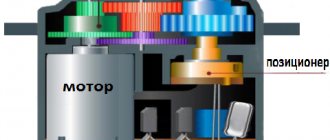
Servo drive device
The servo drive (see figure) consists of a direct current electric motor that drives a gearbox that reduces the speed of rotation of the motor and, at the same time, increases the torque on the shaft. To control the position of the output shaft, it is connected to a position sensor (usually a variable resistor). To control the power and direction in which the servo motor turns, the control circuit uses an input signal from the position sensor in combination with a control signal to set the desired position.
The control unit, having received the value of the desired shaft position through the control signal, subtracts from it the value of its actual position and generates an “error signal”, which can be positive or negative. This "error signal" is applied to power the motor, causing it to change the position of the shaft in the desired direction. The greater the difference between the desired and actual output shaft position, the faster the motor will turn to the desired position. The closer to zero the error (mismatch) value becomes, the less power the motor receives.
Servo motor control
The control signal to the servo motor is not a voltage, as you might expect, but a pulse width modulation (PWM) signal. This signal is standard for all amateur servos and looks as shown in the following figure.
The servo motor waits for a control pulse to arrive every 20 ms. A 1.5 ms pulse will set the servomotor to the center position corresponding to a 90° rotation of the output shaft. Shorter pulses of 1.0 ms will set the output shaft to the initial position of 0°, and pulses of 2.0 ms will set the output shaft to the extreme position of 180°. In reality, this range may be slightly less than a full 180°, without the pulses being shortened at one end and lengthened at the other. It is also not uncommon for a situation where an impulse of 0.5 ms is needed for 0°, and 2.5 ms for 180°.
Assignment of servomotor contacts
Shown in the following figure. I think everything is simple and clear here.
1. Red = Positive supply voltage (4.8V to 6V) 2. Brown = Ground 3. Orange = Control Signal (PWM Pin)
Where to buy popular servos SG90, MG995, MG996
| The most affordable servo option SG90 1.6KG | Servo drives SG90 and MG90S for Arduino at a price below 70 rubles |
| Another option for the SG90 Pro 9g servo from a trusted supplier on Ali | Servo SG90 from reliable supplier RobotDyn |
| Servo tester | Several options for servo testers |
| Protected servo drive with a torque of 15 kg | Servo JX DC5821LV 21KG Full waterproof Core mental gear 1/8 1/10 RC car Scaler Buggy Crawler TRAXXAS RC4WD TRX-4 SCX10 D90 |
| Servo MG996R MG996 Servo Metal Gear for Futaba JR | Servo 13KG 15KG Servos Digital MG995 MG996 MG996R Servo Metal Gear |
Servo control
The decisive factor in controlling servo drives is the control signal, which consists of pulses of constant frequency and variable width.
Pulse length is one of the most important parameters that determines the position of the servo. This length can be set in the program manually using the corner selection method or using library commands. For each brand of device, the length may be different. When the signal enters the control circuit, the generator delivers its pulse, the duration of which is determined using a potentiometer. In another part of the circuit, the duration of the applied signal and the signal from the generator are compared. If these signals are different in duration, the electric motor is turned on, the direction of rotation of which is determined by which of the pulses is shorter. When the pulse lengths are equal, the motor stops.
The standard frequency at which pulses are given is 50 Hz, that is, 1 pulse every 20 milliseconds. At these values, the duration is 1520 microseconds, and the servo is in the middle position. Changing the pulse length leads to rotation of the servo drive - when the duration increases, the rotation is clockwise, and when it decreases, it is rotated counterclockwise. There are duration limits - in Arduino in the Servo library, for 0° the pulse value is set to 544 μs (lower limit), for 180° - 2400 μs (upper limit).
(Image used from amperka.ru)
It is important to consider that on a specific device, the settings may differ slightly from the generally accepted values. For some devices, the average pulse position and width may be 760 µs. All accepted values may also vary slightly due to errors that may occur during the production of the device.
The drive control method is often mistakenly called PWM/PWM, but this is not entirely correct. Control directly depends on the pulse length; the frequency of their occurrence is not so important. Correct operation will be ensured at both 40 Hz and 60 Hz; only a strong decrease or increase in frequency will contribute. If there is a sharp decline, the servo drive will begin to operate jerkily; if the frequency is increased above 100 Hz, the device may overheat. Therefore, it is more correct to call it PDM.
Based on the internal interface, analogue and digital servos can be distinguished. There are no external differences - all the differences are only in the internal electronics. The analog servo drive contains a special chip inside, while the digital servo drive contains a microprocessor that receives and analyzes pulses.
When receiving a signal, the analog servo decides whether or not to change the position and, if necessary, supplies a signal with a frequency of 50 Hz to the motor. During the reaction time (20 ms), external influences may occur that change the position of the servo drive, and the device will not have time to react. A digital servo drive uses a processor that supplies and processes signals at a higher frequency - from 200 Hz, so it can respond faster to external influences and quickly develop the desired speed and torque. Therefore, the digital servo will be better able to hold the set position. At the same time, digital servo drives require more electricity to operate, which increases their cost. The complexity of their production also makes a big contribution to the price. High cost is the only drawback of digital servos; technically, they are much better than analog devices.
Connecting a servo motor to Arduino
The servo drive has three contacts, which are painted in different colors. The brown wire leads to ground, the red wire leads to the +5V power supply, and the orange or yellow wire leads to the signal wire. The device is connected to the Arduino via a breadboard in the manner shown in the figure. The orange wire (signal) is connected to the digital pin, the black and red wires are connected to ground and power, respectively. To control the servomotor, you do not need to connect specifically to shim pins - we have already described the principle of servo control earlier.
It is not recommended to connect powerful servos directly to the board, because... they create a current for the Arduino power circuit that is not compatible with life - you’ll be lucky if the protection works. Most often, the symptoms of overload and improper power supply of the servo are the “jerking” of the servo, an unpleasant sound and the board rebooting. For power supply, it is better to use external sources, be sure to combine the grounds of the two circuits.
Connecting a servo drive to Arduino.
A servo drive can be connected to an Arduino programmable controller to achieve a wide variety of robotics goals. The connection is made through cables that come out of the servo. Typically there are three cables: red; brown or black; yellow, orange or white.
The servo drive is connected to the Arduino board via PWM pins. We have already discussed what PWM (PWM) is in the lesson: Smoothly turning on an LED on Arduino using PWM (PWM)
Let's take the lesson Connecting a button and an LED on an Arduino board to the circuit as a basis, add a servo drive and this is what we should get.
Let's change the code:
#include // connect the library for working with the servo drive Servo servo;
// declare a servo variable of type “servo” int led_pin=3; // connection pin int button_pin = 4; // button pin // variables int buttonState = 0; // variable to store the state of the button void setup() { pinMode(led_pin, OUTPUT); // Initialize digital input/output in output mode. pinMode(button_pin, INPUT); // Initialize digital input/output in input mode. servo.attach(5); // bind the servo drive to analog output 10 } void loop() { buttonState = digitalRead(button_pin);// read the values from the button input if (buttonState == HIGH) { digitalWrite(led_pin, HIGH);// light the LED servo.write (0); //set the shaft to 180 delay (1000); // delay 1 second } else { digitalWrite(led_pin, LOW);// turn off the LED servo.write(180); //set the shaft to 0 delay (1000); // delay of 1 second } } #include // connect the library to work with the servo drive We have not worked with libraries yet. A library is a class containing functions that we can use in our program. The library allows you to reduce the amount of written code and the speed of application development.
As you understand, the line above connects our Servo.h library, after which we can use all the functions of this library.
Servo servo; // declare a servo variable of type “servo”
By declaring a variable, we need it to work with the library.
servo.attach(5); // bind the servo to analog output 5
Servo library function.
servo.write(180); //set the shaft to 180
Using this function we can rotate the servo to a given angle.
Sketch for controlling a servo in Arduino
Controlling a servo directly by changing the pulse duration in the sketch is a rather non-trivial task, but fortunately we have an excellent Servo library built into the Arduino development environment. We will consider all the nuances of programming and working with servos in a separate article. Here we give a simple example of using Servo.
The operating algorithm is simple:
- First we connect Servo.h
- Create an object of the Servo class
- In the setup block we indicate which pin the servo is connected to
- We use the object's methods in the usual C++ way. The most popular is the write method, to which we supply an integer value in degrees (for a 360 servo these values will be interpreted differently).
An example of a simple sketch for working with a servo drive
An example of a project in which we immediately first set the servo motor to zero angle and then rotate it 90 degrees.
#include Servo servo; // Create an object void setup() { servo.attach(9); // Indicate to the Servo class object that the servo is attached to pin 9 servo1.write(0); // Set the initial position } void loop() { servo.write(90); // Rotate the servo 90 degrees delay(1000); servo.write(1800); delay(100); servo.write(90); delay(1000); servo.write(0); delay(1000); }
Sketch for two servos
And in this example we work with two servos at once:
#include Servo servo1; // First servo drive Servo servo2; // Second servo void setup() { servo1.attach(9); // Indicate to the Servo class object that the servo is attached to pin 9 servo2.attach(10); // And this servo is connected to pin 10 } void loop() { // Set the positions servo1.write(0); servo2.write(180); delay(20); // Change positions servo2.write(0); servo1.write(180); }
Servo control using potentiometer
In this example, we rotate the servo depending on the value received from the potentiometer. We read the value and convert it to an angle using the map function:
//Fragment of a standard example of using the Servo library void loop() { val = analogRead(A0); // Read the value from the pin to which the potentiometer is connected val = map(val, 0, 1023, 0, 180); // Convert a number in the range from 0 to 1023 into a new range - from 0 to 180. servo.write(val); delay(15); }
Servo drive control according to a given program
When the sequence of actions is known in advance, you can write it into an array and then transfer it to the servo drive one by one.
Let's put together a diagram:
Connecting one servo drive to Arduino
For programmatic control, you can use the following program:
// Software control of the servo drive // (c) Roman Isakov, 2020 // (c) LabData.ru #include #define servo_pin 8 // Connector for connecting a servo #define servo_speed 500 // Command processing speed uint32_t servo_T = 0; // Service variable int pos = 0; // Current command number int prog[] = {180, 100, 80, 90, 85, 90, 85, 90, 70, 60, 50, 40, 20, 10}; // Servo commands Servo servo1; // Servo object void setup() { servo1.attach(servo_pin); // Connect the servo servo_T = millis(); } void loop() { int N = sizeof(prog)/sizeof(int); // number of array elements prog if (millis() - servo_T >= servo_speed) { // Software timer interrupt servo_T = millis(); servo1.write(prog[pos]); // Sending a command to the server pos++; // Select the next command if (pos>=N) pos = 0; // If you reach the end, repeat again } }
Commands can be easily removed and added, the program itself will calculate their number.
Servo drive SG90
Characteristics and connection of SG-90
If you are going to buy the cheapest and simplest servo drive, then the SG 90 will be the best option. This servo is most often used to control small, lightweight mechanisms with a rotation angle from 0° to 180°.
SG90 Specifications:
- Command execution speed 0.12s/60 degrees;
- Power 4.8V;
- Operating temperatures from -30C to 60C;
- Dimensions 3.2 x 1.2 x 3 cm;
- Weight 9 g.
Description SG90
Wire colors are standard. The servo drive is inexpensive and does not provide precise settings for the start and end positions. In order to avoid unnecessary overloads and the characteristic crackling sound in the 0 and 180 degree position, it is better to set the extreme points at 10° and 170°. When operating the device, it is important to monitor the supply voltage. If this indicator is greatly overestimated, the mechanical elements of the gear mechanisms may be damaged.
Controlling multiple servos using a sensor signal
If the control signal depends on some external factors, then you need to connect a corresponding sensor to the Arduino. In this example, an analog angle sensor (potentiometer). We will control two servos independently. The task is to monitor the voltage on the sensor and close one servo in one direction, and the other in the other. As if imitating a gate.
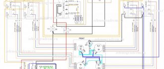
The connection diagram looks like this:
Connecting two servos and a sensor to Arduino
The algorithm is implemented in the Arduino program:
// Control of servos from the sensor // (c) Roman Isakov, 2020 // (c) LabData.ru #include #define servo_speed 200 // Setting the operating speed #define servo1_pin 8 // Output 1 servo #define servo2_pin 9 // Output 2 servos uint32_t servo_T = 0; #define DAT_pin A0 // Potentiometer input Servo servo1; Servo servo2; void setup() { servo1.attach(servo1_pin); servo2.attach(servo2_pin); servo_T = millis(); } void loop() { if (millis() - servo_T >= servo_speed) { servo_T = millis(); int DAT = analogRead(DAT_pin); // Receive an analog signal from the potentiometer servo1.write(map(DAT, 0, 1024, 90, 180)); // Convert the voltage level from 0..1024 to an angle from 90 to 180* and send it to 1 servo servo2.write(map(DAT, 0, 1024, 90, 0)); // Convert the voltage level from 0..1024 to an angle from 90 to 0* and send it to the 2nd server } }
By turning the potentiometer knob, the servos will move and begin to monitor the angle of rotation.
Servo drives MG995 and MG996 tower pro
The MG995 servo is the second most popular servo model most often connected to Arduino projects. These are relatively inexpensive servo motors with much better performance than the SG90.
Specifications MG995
The output shaft on the MG995 rotates 120 degrees (60 in each direction), although many sellers indicate 180 degrees. The device is housed in a plastic case.
- Weight 55 g;
- Torque 8.5 kg x cm;
- Speed 0.2s/60 degrees (at 4.8V);
- Working power 4.8 – 7.2V;
- Operating temperatures – from 0C to -55C.
Description MG995
The connection to the Arduino also occurs via three wires. In principle, for amateur projects it is possible to connect the MG995 directly to the Arduino, but the motor current will always create a dangerous load on the board inputs, so it is still recommended to power the servo separately, not forgetting to connect the ground of both power circuits. Another option that makes life easier would be to use ready-made servo controllers and shields, which we will review in a separate article.
MG996R is similar to MG995 in its characteristics, only it comes in a metal case.
Servo drive control using potentiometer.
#include Servo myservo; int potpin = 0; int val; void setup() { myservo.attach(9); } void loop() { val = analogRead(potpin); val = map(val, 0, 1023, 0, 180); myservo.write(val); delay(15); }
Connection diagram of servo drive and potentiometer to Arduino.
Next lesson: IR Remote. Turn on/off LED.
Converting a servo drive into a continuous rotation servo
As described above, the servo is controlled by variable width pulses that set the angle of rotation. The current position is read from the potentiometer. If you disconnect the shaft and the potentiometer, the servomotor will take the position of the potentiometer slide as at the midpoint. All these actions will lead to feedback being removed. This allows you to control the speed and direction of rotation via the signal wire, and create a continuous rotation servo. It is important to note that a constant rotation servo cannot rotate through a certain angle and make a strictly specified number of revolutions.
To perform the above steps, you will have to disassemble the device and make changes to the design.
In Arduino IDE you need to create a small sketch that will put the rocker in the middle position.
#include Servo myservo; void setup(){ myservo.attach(9); myservo.write(90); } void loop(){ }
After this, the device needs to be connected to Arduino. When connected, the servo will begin to rotate. It is necessary to achieve its complete stop by adjusting the resistor. After the rotation stops, you need to find the shaft, pull out the flexible element from it and install it back.
This method has several disadvantages - setting the resistor to a complete stop is unstable; with the slightest shock/heating/cooling, the adjusted zero point may be lost. Therefore, it is better to use the method of replacing the potentiometer with a trimmer. To do this, you need to remove the potentiometer and replace it with a trimmer resistor with the same resistance. The zero point must be adjusted using a calibration sketch.
Any method of converting a servo into a continuous rotation servo has its drawbacks. Firstly, it is difficult to adjust the zero point; any movement can throw it off. Secondly, the control range is small - with a small change in the pulse width, the speed can change significantly. You can expand the range programmatically in Arduino.
Arduino for beginners. Lesson 4. Servo control
04/13/2014 Entertaining robotics
Servo
We continue the series of lessons “Arduino for Beginners”. Today we are assembling a model with a servo drive - this is also one of the basic circuits. Servos are used in robotics to control the movements of a robot. In addition to the video instructions, the post contains a listing of the program and a connection diagram.
A servo is a motor whose shaft position we can control. It differs from a conventional motor in that it can be set exactly in degrees to the position in which the shaft will fit. Servos are used to simulate various mechanical movements of robots.
Video instructions for assembling the model:
To assemble a model with a servo drive we will need:
- Arduino board
- 3 male-to-male wires
- servo
- Arduino IDE program, which can be downloaded from the Arduino website.
Components for assembling an Arduino model with a servo drive
Connection diagram for Arduino model with servo drive:
Servo drive connection diagram on Arduino
The following program is suitable for this model to work (you can simply copy the program into the Arduino IDE):
#include //use the library to work with the servo drive Servo servo; //declare a servo variable of type Servo void setup() //procedure setup { servo.attach(10); //bind the drive to port 10 } void loop() //procedure loop { servo.write(0); //set the shaft to 0 delay(2000); //wait 2 seconds servo.write(180); //set the shaft to 180 delay(2000); //wait 2 seconds }
The last four commands of the program set the angle of rotation of the servo shaft and the waiting time (in milliseconds) until the next rotation. These numbers can be changed - in the video in the second version we set 0-1000-90-1000, which means turning 90 degrees with a wait of 1 second (1000 milliseconds), returning back, etc. (the loop procedure is repeated cyclically).
Also, in this tutorial we are using libraries for the first time.
A library is a set of additional commands that allows you to enter a program in a simplified format. Here we use the Servo.h library for working with servos.
This is what the assembled Arduino model with a servo drive looks like:
Assembled Arduino model with servo drive
To be continued!
See also:
Training course "Arduino for beginners": main page.
Lesson posts:
- First Lesson: LED
- Lesson two: Button
- Lesson Three: Potentiometer
- Lesson Four: Servo Drive
- Lesson Five: Tri-color LED
- Lesson six: Piezo element
- Lesson seven: Photoresistor
- Eighth lesson: Motion sensor (PIR) and E-mail
- Lesson Nine: Connecting a DHT11 or DHT22 temperature and humidity sensor
All posts of the site “Entertaining Robotics” under the Arduino tag.
Our YouTube channel, where video tutorials are published.
Don't know where to buy Arduino? All components used in the lesson are included in most ready-made Arduino kits, they can also be purchased separately. Detailed selection instructions are here. Low prices, special offers and free shipping on AliExpress and DealExtreme. If you don’t have time to wait for a package from China, we recommend the online stores Amperka and DESSY. Low prices and fast delivery are offered by the ROBstore online store. See also the list of stores.
Author: Alexander Gagarin.