Among the variety of types of electric motors produced today, asynchronous motors have become widespread. Their power and efficiency ensure their use in the woodworking and metalworking industries, in pumping units, factories, machine tools and hand-held power tools.
asynchronous three-phase motor
Operating principle
The principle of operation of an electric motor demonstrates the simplest experiment that we were all shown at school - the rotation of a frame with current in the field of a permanent magnet.
The frame with current is an analogue of the rotor, the stationary magnet is the stator. If current is applied to the frame, it will turn perpendicular to the direction of the magnetic field and freeze in this position. If you force the magnet to spin, the frame will rotate at the same speed , that is, synchronously with the magnet. We have a synchronous electric motor. But our magnet is a stator, and by definition it is motionless. How to make the magnetic field of a stationary stator rotate?
First, let's replace the permanent magnet with a current-carrying coil. This is the winding of our stator. As is known from the same school physics, a coil with current creates a magnetic field. The latter is proportional to the magnitude of the current, and the polarity depends on the direction of the current in the coil. If we apply alternating current to the coil, we get an alternating field.
Magnetic field is a vector quantity. The alternating current in the supply network has a sinusoidal shape.
A very clear analogy with a clock will help us. What vectors constantly rotate before our eyes? These are the hour hands . Let's imagine that there is a clock hanging in the corner of the room. The second hand rotates one full revolution per minute. An arrow is a vector of unit length.
The shadow that the arrow casts on the wall varies as a sine with a period of 1 minute, and the shadow cast on the floor changes as a cosine. Or a sine phase shifted by 90 degrees. But a vector is equal to the sum of its projections. In other words, the arrow is equal to the vector sum of its shadows.
Purpose, design and principle of operation of single-phase asynchronous motorsSingle-phase asynchronous motors are low-power machines, which in design resemble similar three-phase electric motors with a squirrel-cage rotor.
Single-phase asynchronous motors differ from three-phase motors in the design of the stator, where in the grooves of the magnetic circuit there is a two-phase winding, consisting of the main, or working, phase with a phase zone of 120 el. hail and leads to terminals marked C1 and C2, and an auxiliary, or starting, phase with a phase zone of 60 el. hail and leads to terminals marked B1 and B2 (Fig. 1).
The magnetic axes of these phases of the winding are shifted relative to each other at an angle of 0 = 90 el. hail One working phase connected to the AC supply network cannot cause rotation of the rotor, since its current is excited by an alternating magnetic field with a fixed axis of symmetry, characterized by magnetic induction varying harmoniously with time.
Rice. 1. Connection diagram of a single-phase asynchronous motor with a squirrel-cage rotor.
This field can be represented by two components - identical circular magnetic fields of positive and negative sequences, rotating with magnetic inductions, rotating in opposite directions at the same speed. However, with preliminary acceleration of the rotor in the required direction, it continues to rotate in the same direction when the operating phase is turned on.
For this reason, starting a single-phase motor begins with accelerating the rotor by pressing the start button, causing the excitation of currents in both phases of the stator winding, which are shifted in phase by an amount depending on the parameters of the phase-shifting device Z, made in the form of a resistor, inductive coil or capacitor, and elements electrical circuits, which include the operating and starting phases of the stator winding. These currents induce a rotating magnetic field in the machine with magnetic induction in the air gap, which periodically and monotonically changes within the limits of maximum and minimum values, and the end of its vector describes an ellipse.
This. The elliptical rotating magnetic field finds EMF and currents in the conductors of the short-circuited winding of the rotor, which, interacting with this field, ensure acceleration of the rotor of a single-phase motor in the direction of rotation of the field, and within a few seconds it reaches almost the rated speed.
Releasing the start button switches the electric motor from a two-phase mode to a single-phase one, which is further supported by the corresponding component of the alternating magnetic field, which, when rotating, slightly advances the rotating rotor due to slip.
Timely disconnection of the starting phase of the stator winding of a single-phase asynchronous motor from the supply network is necessary due to its design, which provides for a short-term operating mode - usually up to 3 s, which eliminates its long-term stay under load due to unacceptable overheating, insulation burning and failure.
Increased reliability of operation of single-phase asynchronous motors is ensured by integrating into the machine body a centrifugal switch with normally open contacts connected to terminals marked VTs and B2, and a thermal relay with similar contacts having terminals marked RT and C1 (Fig. 2, c, d).
The centrifugal switch automatically disconnects the starting phase of the stator winding connected to the terminals marked B1 and B2 when the rotor reaches a speed close to the nominal one, and the thermal relay - both phases of the stator winding from the supply network when their heating is higher than permissible.
Changing the direction of rotation of the rotor is achieved by changing the direction of the current in one of the phases of the stator winding at start-up by switching the start button and rearranging the metal plate on the motor terminals (Fig. 2, a, b) or only by rearranging two similar plates (Fig. 2, c, d ).
Rice. 2. Marking of the phase terminals of the stator winding of a single-phase asynchronous motor with a squirrel-cage rotor and their connection for rotor rotation: a, c - right, b, d - left.
Comparison of technical characteristics of single-phase and three-phase asynchronous motors
Single-phase asynchronous motors differ from three-phase machines with similar rated power by a lower multiplicity of the initial starting torque kп = Mп / Mnom and an increased multiplicity of the starting current ki = Mi / Mnom, which are for single-phase electric motors with a starting phase of the stator winding, which has an increased resistance to direct current and. values of kп - 1.0 - 1.5 and ki = 5 - 9 have lower inductance than the working phase.
The starting characteristics of single-phase asynchronous motors are worse than the similar characteristics of three-phase asynchronous motors due to the fact that the elliptical rotating magnetic field excited when starting single-phase machines with the starting phase of the stator winding, equivalent to two unequal circular rotating magnetic fields - direct and reverse, causes the appearance of a braking effect.
By selecting the parameters of the elements of the electrical circuits of the operating and starting phases of the stator winding, it is possible to ensure the excitation of a circular rotating magnetic field at start-up, which is possible with a phase-shifting element made in the form of a capacitor of appropriate capacity.
Since acceleration of the rotor causes a change in the parameters of the machine circuits, the rotating magnetic field changes from circular to elliptical, thereby worsening the starting characteristics of the engine. Therefore, at a speed of about 0.8 rated, the starting phase of the stator winding of the electric motor is switched off manually or automatically, as a result of which the motor switches to single-phase operation.
Single-phase asynchronous motors with a starting capacitor have a multiple of the initial starting torque kп = 1.7 - 2.4 and a multiple of the initial starting current ki = 3 - 5.
Two-phase asynchronous motors
In two-phase asynchronous motors, both phases of the stator winding with phase zones of 90 el. hail are workers. They are located in the grooves of the stator magnetic circuit so that their magnetic axes form an angle of 90 el. hail These phases of the stator winding differ from each other not only in the number of turns, but also in rated voltages and currents, although at the rated mode of the engine their total powers are the same.
In one of the phases of the stator winding there is a permanent capacitor Cp (Fig. 3, a), which, under the conditions of the nominal motor mode, ensures the excitation of a circular rotating magnetic field. The capacity of this capacitor is determined by the formula:
Cр = I1sinφ1 / 2πfUn2
where I1 and φ1 are, respectively, the current and phase shift between the voltage and current of the stator winding phase circuit without a capacitor in a circular rotating magnetic field, I and U are, respectively, the frequency of the alternating current and the voltage of the supply network, n is the transformation coefficient - the ratio of the effective numbers of winding phase turns stator, respectively, with and without a capacitor, determined by the formula
n = krev2 w2 / krev1 w1
where kob2 and kob1 are the winding coefficients of the corresponding phases of the stator winding with the number of turns w2 and w1.
The voltage at the terminals of a capacitor Uc connected in series with the stator winding phase of a two-phase asynchronous motor, with a circular rotating magnetic field, is higher than the network voltage U and is determined as follows:
Uc = U √1 + n2
The transition to a motor load different from the nominal one is accompanied by a change in the rotating magnetic field, which becomes elliptical instead of circular. This worsens the operating properties of the engine, and during start-up it reduces the initial starting torque to MP Mnom, thereby limiting the use of motors with a permanently switched on capacitor only in installations with easy starting conditions.
To increase the initial starting torque, a starting capacitor Cn is connected in parallel with the working capacitor Cp (Fig. 3, b), the capacitance of which is much greater than the capacitance of the working capacitor and depends on the multiple of the initial starting torque, which can be increased to two or more.
Rice. 3. Connection diagrams for two-phase asynchronous motors with a squirrel-cage rotor: a - with a permanently connected capacitor, b - with working and starting capacitors.
After the rotor accelerates to a speed of 0.6 - 0.7 rated, the starting capacitor is turned off to avoid the transition of a circular rotating magnetic field to an elliptical one, which worsens the performance of the engine.
The starting mode of such capacitor motors is characterized by the following indicators: kп = 1.7 - 2.4 and ki = 4 - 6.
Capacitor motors have better energy performance than single-phase motors with a starting stator winding, and their power factor, due to the use of capacitors, is higher than that of three-phase motors of the same power.
Universal asynchronous motors
In automatic control installations, universal asynchronous motors are used - low-power three-phase machines that are connected to a three-phase or single-phase network. When powered from a single-phase network, the starting and operating characteristics of motors are slightly worse than when used in three-phase mode.
Universal asynchronous motors of the UAD series are manufactured two- and four-pole, which in three-phase mode have a rated power from 1.5 to 70 W, and in single-phase mode - from 1 to 55 W and operate from an alternating voltage network with a frequency of 50 Hz with efficiency η = 0 .09 - 0.65.
Single-phase induction motors with shaded or shaded poles
In single-phase asynchronous motors with split or shielded poles, each pole is split by a deep groove into two unequal parts and carries a single-phase winding covering the entire magnetic circuit of the pole, and short-circuited turns located on its smaller part.
The rotor of these motors has a short-circuited winding. Switching on the stator winding to a sinusoidal voltage is accompanied by the establishment of a current in it and the excitation of an alternating magnetic field with a fixed axis of symmetry, which induces the corresponding emf and currents in the short-circuited turns.
Under the influence of the currents of short-circuited turns, the corresponding MD s excites a magnetic field that prevents the strengthening and weakening of the main magnetic field in the shielded frequent poles. The magnetic fields of the shielded and unshielded parts of the poles are out of phase in time and, being displaced in space, form a resulting elliptical rotating magnetic field, moving in the direction from the magnetic axis of the unshielded part of the pole to the magnetic axis of its shielded part.
The interaction of this field with currents induced in the rotor winding causes the appearance of an initial starting torque Mn = (0.2 - 0.6) Mn and acceleration of the rotor to the rated speed, if the braking torque applied to the motor shaft does not exceed the initial starting torque.
In order to increase the initial starting and maximum torques of single-phase asynchronous motors with split or shielded poles, magnetic shunts made of sheet steel are placed between their poles, which brings the rotating magnetic field closer to a circular one.
Shaded-pole motors are non-reversible devices that allow frequent starts, sudden stops, and can remain in a stalled state for long periods of time. They are manufactured with two- and four-pole rated power from 0.5 to 30 W, and with an improved design up to 300 W for operation from an alternating voltage network with a frequency of 50 Hz with an efficiency ηnom = 0.20 - 0.40.
Two-phase synchronous electric motor
Let's place two windings on the stator at an angle of 90 degrees, that is, mutually perpendicular. Let us supply them with sinusoidal alternating current. The phases of the currents will be shifted by 90 degrees . We have two mutually perpendicular vectors, varying according to a sinusoidal law with a phase shift of 90 degrees. The sum vector will rotate in a clockwise manner, making one complete revolution per period of the alternating current frequency.
We have a two-phase synchronous electric motor. Where can I get the phase-shifted currents to power the windings? Probably not everyone knows that in the beginning AC distribution networks were two-phase. And only later, not without a struggle, did they give way to three-phase ones. If we had not given in, our two-phase electric motor could have been connected directly to two phases.
But three-phase networks won, for which three-phase electric motors were developed. And two-phase electric motors have found their application in single-phase networks in the form of capacitor motors.
Online electrical magazine
Purpose, design and principle of operation of single-phase asynchronous motors
Single-phase asynchronous motors are low-power machines that, in design, resemble similar three-phase electric motors with a squirrel-cage rotor.
Single-phase asynchronous motors differ from three-phase motors in the design of the stator, where in the grooves of the magnetic circuit there is a two-phase winding, consisting of a main, or working, phase with a phase zone of 120 el. hail and leads to terminals marked C1 and C2, and an auxiliary, or starting, phase with a phase zone of 60 el. hail and leads to terminals marked B1 and B2 (Fig. 1).
The magnetic axes of these phases of the winding are shifted relative to each other by an angle of 0 = 90 el. hail One working phase connected to an alternating voltage supply network cannot cause rotation of the rotor, because its current is excited by an alternating magnetic field with a fixed axis of symmetry, characterized by magnetic induction varying harmoniously with time.
Rice. 1. Connection diagram of a single-phase asynchronous motor with a squirrel-cage rotor.
This field can be represented by 2 components - similar radial magnetic fields of direct and reverse sequences, rotating with magnetic inductions, rotating in opposite directions at the same speed. But during the preparatory acceleration of the rotor in the desired direction, it continues to spin in the same direction when the operating phase is turned on.
For this reason, starting a single-phase motor begins with accelerating the rotor by pressing the start button, causing the excitation of currents in both phases of the stator winding, which are shifted in phase by an amount depending on the characteristics of the phase-shifting device Z, made in the form of a resistor, inductive coil or capacitor, and parts electronic circuits, which include the operating and starting phases of the stator winding. These currents induce a rotating magnetic field in the machine with magnetic induction in the air gap, which varies from time to time and uniformly within the boundaries of the largest and smallest values, and the end of its vector outlines an ellipse.
This. The elliptical rotating magnetic field finds EMF and currents in the conductors of the short-circuited winding of the rotor, which, interacting with this field, ensure acceleration of the rotor of a single-phase motor in the direction of rotation of the field, and within a few seconds it reaches almost rated speed.
Releasing the start button switches the electric motor from a two-phase mode to a single-phase one, which is then supported by a corresponding component of the alternating magnetic field, which, during its own rotation, slightly advances the spinning rotor due to slip.
Timely disconnection of the starting phase of the stator winding of a single-phase asynchronous motor from the supply network is necessary due to its design, which provides for a short-term operating mode - usually up to 3 s, which eliminates its long stay under load due to unacceptable overheating, insulation burning and failure.
An increase in the reliability of operation of single-phase asynchronous motors is ensured by integrating into the machine body a centrifugal switch with normally open contacts connected to terminals marked VTs and B2, and a thermal relay with similar contacts having terminals marked RT and C1 (Fig. 2, c, d).
The centrifugal switch automatically disconnects the starting phase of the stator winding connected to the terminals marked B1 and B2 when the rotor reaches a speed close to the nominal one, and the thermal relay disconnects both phases of the stator winding from the supply network when their heating is higher than permissible.
Changing the direction of rotation of the rotor is achieved by configuring the direction of the current in one of the phases of the stator winding at start-up by switching the start button and rearranging the iron plate on the electric motor terminals (Fig. 2, a, b) or only by rearranging 2 similar plates (Fig. 2, c , G).
Rice. 2. Marking of the phase terminals of the stator winding of a single-phase asynchronous motor with a squirrel-cage rotor and their connection for rotor rotation: a, c - right, b, d - left.
Comparison of technical features of single-phase and three-phase asynchronous motors
Single-phase asynchronous motors differ from three-phase machines with similar rated power by a reduced factor of the initial starting torque kп = Мп / Мн and an increased factor of the starting current ki = Mi / Мnom which for single-phase electric motors with a starting phase of the stator winding, which has an increased resistance to constant current and. The values of kп - 1.0 - 1.5 and ki = 5 - 9 have the lowest inductance than the working phase.
The starting properties of single-phase asynchronous motors are worse than those of three-phase asynchronous motors due to the fact that the elliptical rotating magnetic field excited when starting single-phase machines with the starting phase of the stator winding, equivalent to two unequal radial rotating magnetic fields - direct and reverse, causes a braking effect.
By selecting the characteristics of the parts of the electronic circuits of the operating and starting phases of the stator winding, it is possible to ensure the excitation of a radial rotating magnetic field at start-up, which can be the case with a phase-shifting element made in the form of a capacitor of appropriate capacity.
Because acceleration of the rotor causes a change in the characteristics of the machine circuits, the rotating magnetic field changes from radial to elliptical, thereby worsening the starting properties of the motor. Therefore, at a speed of about 0.8 rated, the starting phase of the stator winding of the electric motor is switched off manually or automatically, as a result of which the engine switches to a single-phase operating mode.
Single-phase asynchronous motors with a starting capacitor have a multiple of the initial starting torque kп = 1.7 - 2.4 and a multiple of the initial starting current ki = 3 - 5.
Two-phase asynchronous motors
In two-phase asynchronous motors, both phases of the stator winding with phase zones of 90 el. hail are workers. They are placed in the grooves of the stator magnetic circuit so that their magnetic axes form an angle of 90 el. hail These phases of the stator winding differ from each other not only in the number of turns, but also in rated voltages and currents, although at the rated mode of the motor their total powers are similar.
In one of the phases of the stator winding there is always a capacitor Cp (Fig. 3, a), which, in the conditions of the nominal mode of the motor, ensures the excitation of a radial rotating magnetic field. The capacity of this capacitor is determined by the formula:
Cр = I1sinφ1 / 2πfUn2
where I1 and φ1 are, respectively, the current and phase shift between the voltage and current of the stator winding phase circuit without a capacitor with a radial rotating magnetic field, I and U are, respectively, the frequency of the alternating current and the voltage of the supply network, n is the transformation ratio - the ratio of the effective numbers of winding phase turns stator, respectively, with and without a capacitor, determined by the formula
n = krev2 w2 / krev1 w1
where kob2 and kob1 are the winding coefficients of the corresponding phases of the stator winding with the number of turns w2 and w1.
The voltage at the terminals of the capacitor Uc, connected alternately with the winding phase of a stator-two-phase asynchronous motor, with a radial rotating magnetic field is higher than the network voltage U and is determined as follows:
Uc = U √1 + n2
The transition to a motor load that is different from the rated one is accompanied by a configuration of the rotating magnetic field, which becomes elliptical instead of radial. This aggravates the performance characteristics of the motor, and during start-up it reduces the initial starting torque to MP Mnom, thereby limiting the use of motors with a permanently switched on capacitor exclusively in installations with easy starting criteria.
To increase the initial starting torque, a starting capacitor Cn is connected in parallel with the working capacitor Cp (Fig. 3, b), the capacitance of which is much greater than the capacitance of the working capacitor and depends on the multiple of the initial starting torque, which can be increased to 2 or more.
Rice. 3. Schemes for connecting two-phase asynchronous motors with a squirrel-cage rotor: a - with a permanently connected capacitor, b - with working and starting capacitors.
After the rotor accelerates to a speed of 0.6 - 0.7 rated, the starting capacitor is turned off to avoid the transition of the radial rotating magnetic field to an elliptical one, which worsens the operating properties of the motor.
The starting mode of such capacitor engines is characterized by the following indicators: kп = 1.7 - 2.4 and ki = 4 - 6.
Capacitor motors have better energy performance than single-phase motors with a starting stator winding; their power factor, due to the use of capacitors, is higher than that of three-phase motors of similar power.
Universal asynchronous engines
In automatic control installations, universal asynchronous motors are used - low-power three-phase machines that are connected to a three-phase or single-phase network. When powered from a single-phase network, the starting and operating properties of the engines are somewhat worse than when used in three-phase mode.
Universal asynchronous motors of the UAD series are manufactured with two- and four-pole, which in three-phase mode have a rated power from 1.5 to 70 W, and in single-phase mode - from 1 to 55 W and operate from an alternating voltage network with a frequency of 50 Hz with efficiency η = 0 .09 - 0.65.
Single-phase asynchronous motors with split or shielded poles
In single-phase asynchronous motors with split or shielded poles, each pole is split by a deep groove into two unequal parts and carries a single-phase winding that covers the entire magnetic circuit of the pole, and short-circuited turns located on its smallest part.
The rotor of these engines has a short-circuited winding. Switching on the stator winding to a sinusoidal voltage is accompanied by the establishment of a current in it and the excitation of an alternating magnetic field with a fixed axis of symmetry, which induces the proper emf and currents in the short-circuited turns.
Under the influence of currents of short-circuited turns, the corresponding MD s excites a magnetic field that prevents the strengthening and weakening of the main magnetic field in shielded frequent poles. The magnetic fields of the shielded and unshielded parts of the poles are out of phase in time and, being displaced in space, form a resulting elliptical rotating magnetic field, moving in the direction from the magnetic axis of the unshielded part of the pole to the magnetic axis of its shielded part.
The interaction of this field with currents induced in the rotor winding causes the appearance of an initial starting torque Mn = (0.2 - 0.6) Mn and the acceleration of the rotor to the rated speed, if the braking torque applied to the motor shaft does not exceed the initial starting torque.
In order to increase the initial starting and maximum torques of single-phase asynchronous motors with split or shielded poles, magnetic shunts made of sheet steel are placed between their poles, which brings the rotating magnetic field closer to the radial one.
Shaded-pole motors are non-reversible devices that allow frequent starts, unexpected stops, and can remain in an inhibited state for a long time. They are manufactured with two- and four-pole rated power from 0.5 to 30 W, and with an improved design up to 300 W for operation from an alternating voltage network with a frequency of 50 Hz with an efficiency ηnom = 0.20 - 0.40.
Three-phase synchronous motor
Modern AC distribution networks are made according to a three-phase circuit.
- Three sinusoids are transmitted over the network at once of a third of a period or 120 degrees relative to each other.
- A three-phase motor differs from a two-phase one in that it has not two, but three windings on the stator, rotated 120 degrees.
- Three coils connected to three phases create a total rotating magnetic field that turns the rotor.
How to determine the winding connection diagram?
Recognizing the winding method is quite simple. This can be done in two ways:
Look at the number plate on the engine. Usually it displays all the technical data relating to the operation of the engine. Among other things, you can find two symbols:
- geometric shape of a triangle;
- a star with three rays.
It is necessary to compare which of the symbols in the table is under the value 380V. It may look like this: 220/380V and next to them are the triangle/star symbols. This designation indicates that a star winding operates on a motor connected to a 380V network.
However, the engine does not always have such a sign. It may be missing or worn out. This determination method is more suitable for new engines that have not been repaired or serviced. It is better to check the old unit yourself. This will require a second method of recognizing the type of winding.
Unscrew the control unit and look at the terminal block. You can see 6 wire pins on it. Accordingly, there are 3 beginnings and three ends of the winding. Depending on the type of switching, these outputs can be referred to as the winding method:
- Star method. In this case, the three outputs are connected by one jumper. The three remaining inputs are connected to a separate phase one behind the other.
- Triangle method. Each two wire terminals are connected in series with jumpers. In this way the windings pass into each other. In this case, the power wires are connected to each input individually.
This method gives a complete picture of how the engine works and what circuit it is connected to. Knowing this, you can connect the motor to a 220V network.
INFORMATION: in rare cases, having unscrewed the control unit, you can find not 6 contacts in it, but only 3. This indicates that the switching circuit is located in the engine itself - under the protective casing on the end side.
Three-phase asynchronous motor
Current is supplied to the rotor of a synchronous motor from a power source. But we know from the same school physics that a current in a coil can be created by an alternating magnetic field. You can simply short the ends of the coil to the rotor. You can even leave just one turn, like in a frame. And let the current induce a rotating magnetic field of the stator.
- At the moment of start, the rotor is stationary, and the stator field rotates.
- The field in the rotor circuit changes, inducing an electric current.
- The rotor will begin to catch up with the stator field. But it will never catch up, since in this case the current will cease to be induced in it.
- In an asynchronous motor, the rotor always rotates slower than the magnetic field.
- The difference in speed is called slip. Connecting an asynchronous motor does not require current to be supplied to the rotor winding.
Synchronous and asynchronous motors have their own advantages and disadvantages, but the fact is that the majority of motors used in industry today are three-phase asynchronous motors.
What is an asynchronous motor
An asynchronous motor is an electrical machine capable of converting electrical energy into mechanical energy. Receiving electric current, it sets into motion, which is used directly by units - machines, cars, etc. An asynchronous motor is called because its magnetic field always rotates faster than the rotor. This type of electric motor uses alternating current to operate.
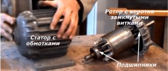
Thus, an asynchronous motor consists of two main components - a rotor and a stator. Being separated from each other, they form a magnetic field between themselves, which sets in motion.
The stator in turn consists of:
- housing that holds all the motor mechanisms together. As a rule, they are solid cast due to their ease of manufacture and strength;
- a core consisting of electrical steel plates. It increases the magnetic and inductive properties of the device;
- windings, installed in the grooves of the core. These are coils of copper wire that connect directly to the network itself.
The rotor is a little simpler and has a ventilation impeller that transfers mechanical energy from the stator. There are two types of rotors:
- massive - uses a solid circuit and a ferromagnetic connection;
- short-circuited - based on rings of conductors.
Despite the differences in structure, such asynchronous motors operate on the same principle.
Single-phase asynchronous electric motor
If we leave a short-circuited coil on the rotor and one coil on the stator, we will get an amazing design - an asynchronous single-phase motor.
At first glance, it seems that such an engine should not work. After all, there is no current in the rotor , and the magnetic field of the stator does not rotate. But if you push the rotor by hand in any direction, the engine will start! And it will rotate in the direction in which it was pushed at launch.
The operation of this motor can be explained by imagining the stationary alternating magnetic field of the stator as the sum of two fields rotating towards each other. While the rotor is stationary, these fields balance each other, so a single-phase asynchronous motor cannot start on its own. If the rotor is set in motion by an external force, it will rotate in parallel with one vector and towards the other.
A passing vector will pull the rotor along with it, a counter vector will slow it down.
It can be shown that due to the difference between the head and tail speeds, the influence of the tail vector will be stronger, and the engine will operate in asynchronous mode.
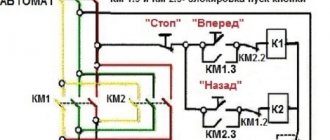
§82. Single-phase and two-phase asynchronous motors
Single-phase and two-phase asynchronous motors.
The operating principle of a single-phase motor. In a single-phase asynchronous motor, the stator winding is located in slots occupying approximately 2/3 of the circle corresponding to a pair of poles (Fig. 270, a). For this reason, the power of a single-phase motor is also about 2/3 of the power of a three-phase motor with the same overall dimensions.
The single-phase stator winding 2 creates a pulsating magnetic field, which can be represented as two fields rotating in different directions with a frequency n1 (Fig. 270, b). Field 5, which rotates in the same direction as rotor 3, is called direct field; field 6, rotating in the opposite direction, is a reverse field. These fields, acting on the rotor, create two oppositely directed electromagnetic moments Mpr and Mobr. Therefore single-phase asynchronous
Rice. 270. Section of a single-phase asynchronous motor (a), forward and reverse rotating magnetic fields (b)
Rice. 271. Dependences of M(s) of a single-phase motor on forward and reverse rotating fields
The motor can be represented as two completely identical three-phase motors, the rotors of which are closely connected to each other, and the windings are connected to a three-phase network so that their magnetic fields rotate in opposite directions.
However, if the rotor is spun in any direction, then the moments Mpr and Mobr will not be equal. In this case, a certain resulting moment Mres will act on the motor shaft, which will ensure its further rotation in a given direction. This is explained by the fact that the current in the rotor winding, created by the reverse field, has a strong demagnetizing effect and significantly weakens the reverse field.
From the analysis of the M(s) curves shown in Fig. 271, it follows that:
a single-phase motor does not have an initial starting torque because when s = 1, i.e., with a stationary rotor, the resulting torque MP = 0;
The rotation speed of a single-phase motor at idle is lower than that of a three-phase motor due to the presence of braking torque Mobr. For the same reason, a single-phase motor has worse performance characteristics: lower efficiency, lower overload capacity, increased slip at rated load.
Starting devices . To obtain starting torque, single-phase motors are equipped with a starting winding I, located with a shift of 90° relative to the main working winding P (Fig. 272, a and b). During the start-up period, the starting winding is connected to the network through phase-shifting elements - a capacitor or resistor. After the engine has finished accelerating, the starting winding is turned off and the engine continues to operate as a single-phase one. Since the starting winding operates only for a short time, it is made of wire of a smaller cross-section compared to the working winding and is placed in a smaller number of grooves.
If you use capacitor C as a phase-shifting element (Fig. 273, a), then you can obtain an operating mode at start-up that is close to symmetrical, i.e., obtain a circular rotating field.
Under light starting conditions (small load torque during the starting period), motors with a starting resistor R are used (Fig. 273,b). The presence of a resistor in the starting winding circuit provides a smaller phase shift ?1 between voltage and current in this winding than the phase shift ?2 in the working winding. Due to this
Rice. 272. Location of stator windings in a two-phase two-pole machine
The currents in the working and starting windings turn out to be shifted in phase by an angle ?1 – ?2 and form an asymmetrical (elliptical) rotating field, due to which the starting torque occurs. Single-phase motors with capacitor starting and motors with starting resistor have high operational reliability.
Since turning on the second winding significantly improves the characteristics of the motor, in some cases two-phase motors are used in which both windings are constantly on. If a 90° phase shift between the currents in phases A and B (Fig. 274) is carried out by including capacitors in one of them, then such motors are called capacitor motors.
In two-phase motors, both windings A and B occupy, as a rule, the same number of slots and have equal power. When starting a capacitor motor, it is rational to have an increased capacity Cp + Sp. After accelerating the motor and reducing the current, part of the capacitors Cn is turned off in order to increase the capacitive reactance and at rated mode (when the motor current becomes less than at start-up) to ensure the operating mode of the motor
Rice. 273. Starting schemes for a single-phase asynchronous motor using a capacitor (a) and a resistor (b)
Rice. 274. Scheme of a capacitor asynchronous motor
Rice. 275. Design of a single-phase asynchronous motor with a squirrel cage on the rotor (a) and with a hollow non-magnetic rotor (b): 1-stator winding; 2 – body; 3 – external stator; 4 – rotor; 5 — bearing shield; 6 - shaft; 7 - internal stator
ateler in conditions similar to operating conditions in a circular rotating field.
Device. Single-phase and two-phase asynchronous motors are designed in the same way as three-phase ones: they have single-phase or two-phase stator windings and a squirrel-cage rotor with a squirrel cage (Fig. 275, a). Single-phase motors with a hollow non-magnetic rotor (Fig. 275, b) and an external stator on which two windings are located, shifted in space by 90°, are widely used. The rotor is made in the form of a thin-walled hollow cylinder made of aluminum. To reduce the magnetic resistance of the motor magnetic circuit, there is an internal stator made of electrical steel sheets, just like the external stator.
A hollow rotor can be represented as a collection of elementary conductors. The rotating magnetic field created by the stator winding induces an e.g. in each elementary conductor of the hollow rotor. d.s, under the influence of which eddy currents flow through them. As a result of the interaction of these currents with the rotating field, electromagnetic forces and torque arise.
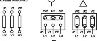
Connection diagram
It is possible to connect loads to a three-phase network using two circuits - star and delta. When connected by a star, the beginnings of the windings are connected to each other, and the ends are connected to the phases. When switched on in a triangle, the end of one winding is connected to the beginning of the other.
In a star connection circuit, the windings are under a phase voltage of 220 V; when connected in a delta, they are under a linear voltage of 380 V.
When switched on by a triangle, the motor develops not only more power, but also large starting currents. Therefore, sometimes they use a combined scheme - starting with a star, then switching to a triangle.
The direction of rotation is determined by the order in which the phases are connected. To change the direction, it is enough to swap any two phases.
Connection
To operate the device, 1 phase with a voltage of 220 Volts is required. This means that you can plug it into a household outlet. This is precisely the reason for the popularity of the engine among the population. All household appliances, from a juicer to a grinder, have mechanisms of this type.
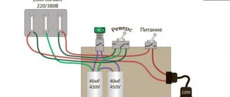
connection with starting and running capacitors
There are 2 types of electric motors: with a starting winding and with a working capacitor:
- In the first type of device , the starting winding operates via a capacitor only during start. Once the machine reaches normal speed, it turns off and operation continues with one winding.
- In the second case , for motors with a working capacitor, the additional winding is permanently connected through the capacitor.
An electric motor can be taken from one device and connected to another. For example, a working single-phase motor from a washing machine or vacuum cleaner can be used to operate a lawn mower, processing machine, etc.
There are 3 schemes for switching on a single-phase motor:
- In scheme 1 , the work of the starting winding is performed by means of a capacitor and only for the starting period.
- 2 circuit also provides for a short-term connection, but it occurs through a resistance and not through a capacitor.
- Scheme 3 is the most common. In this scheme, the capacitor is constantly connected to a source of electricity, and not just during startup.
Connecting an electric motor with starting resistance:
- The auxiliary winding of such devices has increased active resistance.
- To start an electrical machine of this type, a starting resistor can be used. It should be connected in series to the starting winding. Thus, it is possible to obtain a phase shift of 30° between the winding currents, which will be quite enough to start the mechanism.
- Alternatively , a phase shift can be obtained by using a starting phase with a higher resistance value and a lower inductance value. This winding has fewer turns and thinner wire.
Connecting a motor with capacitor start:
- For these electric machines, the starting circuit contains a capacitor and is turned on only for the start period.
- To achieve the maximum starting torque, a circular magnetic field is required that performs the rotation. For it to occur, the winding currents must be rotated 90° relative to each other. Phase-shifting elements such as a resistor and inductor do not provide the necessary phase shift. Only the inclusion of a capacitor in the circuit allows you to obtain a phase shift of 90°, if you select the capacitance correctly.
- calculate which wires belong to which winding by measuring the resistance. For the working winding, its value is always less (about 12 Ohms) than for the starting winding (usually about 30 Ohms). Accordingly, the cross-section of the working winding wire is larger than that of the starting winding.
- The capacitor is selected according to the current consumed by the motor. For example, if the current is 1.4 A, then a capacitor with a capacity of 6 μF is required.
220 volt connection
Unlike a three-phase motor, a two-phase motor is initially designed to be connected to a single-phase network. To obtain a phase shift between the windings, a working capacitor is switched on, which is why two-phase motors are also called capacitor motors.
The capacity of the working capacitor is calculated using formulas for the nominal operating mode. But when the mode differs from the nominal one, for example, during startup, the balance of the windings is disrupted . To ensure the starting mode during start and acceleration, an additional starting capacitor is connected in parallel to the working one, which must be turned off when reaching the rated speed.
Polyphase motors
Multiphase motors are not widely used. The possibility of using this type of equipment is relevant when it is necessary to obtain a higher synchronous shaft rotation speed when the engine starts operating. But this type will require a more complex work management system. This increases the possibility of dynamic and static errors during startup.
In conclusion, a few main points. Electric motors are irreplaceable equipment designed to operate household appliances and industrial machines. The most common type of asynchronous units is for a three-phase network. But this equipment, if necessary, can be installed in a single-phase network with a slight loss of power.