But what to do if only two wires enter the area (zero and phase), that is, a single-phase voltage of 220 volts is supplied to the area? There is only one way out - to connect a 380 to 220 V electric motor, for which you can use different circuits.
Connection diagram of a three-phase motor to a single-phase network.
Let’s immediately make a reservation that the best option is to connect an electric motor operating at 380V to a three-phase network. This will ensure both the rated power of the device and the rated rotation, hence the efficiency of the unit. Therefore, any interference with the parameters creates conditions for a decrease in the quality of operation.
Connection diagrams
Basically, connecting an electric motor to a single-phase network is done by connecting two supply wires according to either a triangle or a star. In the first case, the output power of the motor will differ from the rated one (that is, with a three-phase connection) by 30%. In the second, by 50%. That is, the triangle scheme in this case is effective.
There are three wires sticking out of the electric motor. So the phase of the supply wire is connected to one of them, zero to the other. But the third wire is connected to the circuit through a capacitor.
Attention! The rotation of the electric motor shaft in one direction or the other depends on which wire the capacitor is connected to: to phase or to zero. To change the direction of rotation, you simply need to re-wire the wires.
And the third parameter is the rotation speed. So it is no different from the nominal one. That is, if the electric motor rotates, for example, 1280 rpm from a three-phase network, then when connected to a single-phase network it will rotate at the same frequency.
Connecting an electric motor 380V to 220V
To bookmarks
General rules for connecting an electric motor through a capacitor.
The 380V to 220V electric motor is connected via a capacitor. For such a connection, it is necessary to use paper (or starting) capacitors , and it is IMPORTANT that the rated voltage of the capacitor is greater than or equal to the mains voltage (it is recommended that the capacitor voltage be 2 times the mains voltage). The following brands (types) of capacitors can be used:
MBGO, MBGCh, MBGP, MBGT, MBGV, KBG, BGT, OMBG, K42-4, K42-19, etc.
The capacitance of the capacitor can be determined using the formulas given below, or using an online capacitance calculation.
The first thing you need to do is to correctly connect the leads of the motor windings. As is already known from the article: connection diagrams for electric motor windings electric motor windings can be connected according to a “star” circuit (denoted by Y) or by a “delta” circuit (denoted by Δ), while, as a rule, a “triangle” circuit is used to connect a 220V electric motor "In order to determine the winding connection diagram, you need to look at the passport data of the electric motor on the nameplate attached to it:
The entry: “Δ/ Y 220/380V” means that to connect this electric motor to 220V, you need to connect its windings in a delta , and to connect to 380V, in a star ; read how to do this here .
The second thing you need to decide is how the electric motor will be started, under load (when at the moment of starting the electric motor a load is applied to its shaft and it cannot rotate freely) or without load (when the electric motor shaft rotates freely at the moment of starting, for example, emery , fan, circular saw, etc.).
When starting the engine without load, 1 capacitor is used, which is called a working capacitor, and if it is necessary to start the engine under load, in addition to the working one, a second capacitor is additionally used in the circuit, which is called a starting capacitor, it is turned on only at the moment of starting.
Let's look at the connection diagrams for a 380 by 220 electric motor for both cases:
Schemes for connecting an electric motor through a capacitor.
1) Connecting the electric motor through a capacitor in a delta pattern, starting without load:
The capacity of the working capacitor for connecting an electric motor with a “triangle” winding connection diagram is calculated by the formula:
C r =4800 * I n / U s ; ICF
where: I n - rated current of the electric motor in Amperes (accepted in accordance with the passport data of the electric motor); U с - network voltage in Volts.
In the circuit, a single-pole circuit breaker is used to turn on the electric motor, but its use is not necessary; you can turn on the electric motor directly to the network through an outlet using a regular plug or, for example, turn it on through a regular light switch.
2) Connecting the electric motor via a capacitor in a star configuration, starting without load:
The capacity of the working capacitor for connecting an electric motor with a star connection of the windings is calculated by the formula:
C r =2800 * I n / U s ; ICF
where: I n - rated current of the electric motor in Amperes (accepted in accordance with the passport data of the electric motor); U с - network voltage in Volts.
If a 380 to 220 Volt engine starts under load, a starting capacitor must additionally be used in the circuit, otherwise the torque on the electric motor shaft will not be enough to spin it up and the engine will not be able to start.
The starting capacitor is connected in parallel with the working capacitor and should be turned on only when the engine starts; after the engine picks up speed it must be turned off.
The capacity of the starting capacitor should be 2.5 - 3 times greater than the working capacitor.
C p = (2.5…3) * C p ; ICF
With this scheme, to start the electric motor, you must press and hold the SB button, then apply voltage by turning on the circuit breaker; as soon as the engine starts, the SB button must be released. You can also use a regular switch as a button.
However, the best option for connecting a 380 to 220 electric motor is to use PNVS-10 (push-type starter with starting contact):
The “start” buttons in these starters have 2 contacts, one of them, when the “start” button is released, opens, turning off the starting capacitor, and the second remains closed and through it voltage is supplied to the electric motor through the working capacitor; the shutdown is performed by the “stop” button.
Reverse of an electric motor connected to 220 Volts through a capacitor.
So, from the diagrams above it follows that with any method of connecting the windings (star or delta), there are three points left in the motor terminal box for connecting it to the network, conditionally: zero is connected to the first terminal, phase is connected to the second, and phase is supplied to the third through a capacitor, but what to do if the engine starts to rotate in the wrong direction when starting? To change the direction of rotation of a motor connected through a capacitor, you simply need to switch the phase wire from one terminal of the electric motor to another, while leaving the neutral wire at the same terminal, i.e. conditionally: leave zero on the first terminal, apply the phase to the third, and apply the phase to the second through a capacitor.
Because switching the terminals in the terminal box takes a certain time, then if it is necessary to frequently change the direction of rotation of the capacitor motor, it is better to use a connection diagram via a single-pole packet switch in 2 directions:
With this scheme, in the package switch position “0” the engine will be turned off, and in positions “1” and “2” it will start clockwise or counterclockwise.
Using a group (block) of capacitors.
When connecting an electric motor through a capacitor, it is very important to select its capacitance as accurately as possible. The closer the value of the actual capacitor capacitance is to the calculated one, the more optimal the shift of the voltage vector relative to the current vector will be, which in turn will give higher torque on the motor shaft and its efficiency.
For example: according to the calculation, the required capacitance of the working capacitor was 54 µF, but it is not possible to find a capacitor of suitable capacitance, in this case the most appropriate option is to use a group of parallel-connected capacitors (capacitor block).
As you know, when connecting capacitors in parallel, their capacitance is summed up, so to get the 54 µF we need, you can use 2 parallel-connected capacitors - 40 and 14 µF (40 + 14 = 54), or any other number of capacitors whose total capacitance will give the desired value, for example 30, 20 and 4 µF:
Note: All capacitors in a group must be the same type, voltage rating and frequency.
For more information about connection diagrams for capacitors and calculating their characteristics, read the article: Connection diagrams for capacitors - calculation of capacitance.
Was this article useful to you? Or maybe you still have questions ? Write in the comments!
Didn’t find an article on the website on a topic that interests you regarding electrical engineering? Write to us here. We will definitely answer you.
↑ Up
7,5
https://elektroshkola.ru/elektrodvigateli/podklyuchenie-elektrodvigatelya-380v-na-220v/
How to choose a capacitor
There are several nuances that relate to the number of connected capacitors.
- If the power of the electric motor does not exceed 1.5 kW, then one working capacitor can be installed in the circuit.
- If the engine immediately runs under load upon start-up or its power exceeds 1.5 kW, then two capacitors will have to be installed in the circuit: a working capacitor and a starting capacitor. Both elements are inserted into the circuit in parallel. In this case, the latter will only work when the engine starts, after which it automatically turns off.
Essentially, the electric motor connection circuit is powered by the “Start” button and the power off switch. To start the engine, you need to press the “Start” button and hold it until the engine is completely turned on. This can be controlled even by ear.
Starting the engine
As you already understand, the engine will be started without the use of a capacitor. To make a connection using this method, it is enough to have the most typical asynchronous motor. Authors of scientific books, among whom is V. Golik, indicate that the nominal speed of the motor rotor should be at the level of 1500 rpm, and not 3000. This is associated with the characteristics of the stator windings.
The power of power units is limited by the electrical parameters of power-type diodes and thyristors, which are 10 amperes, while the reverse voltage exceeds 300 volts. The 3 stator windings must be connected using a triangular connection. The pins are grouped on the terminal block using ordered jumpers.
The 220V voltage is supplied through an automatic safety switch. The connection is made parallel to one of the windings, let's define it as “A”. The remaining two (“B” and “C”) are connected in series with each other and in parallel with “A”. An electronic unit is installed at the outputs of one part, for example, “C”, let’s define it as “K”.
Let's consider a situation in which the block contact is always open and voltage is supplied uninterruptedly. With it, currents of types Ia and Ib+c will flow through the above-described circuits “A”, “B” and “C”. Resistive - inductive resistance levels are the same on all stator windings. This feature causes the current to be twice as high in chain “A” compared to the direction Ib+c. The phase coincidence of the circuits will be observed.
Each current individually creates magnetized fluxes near itself, which do not set the rotor element in motion. To ensure the operation of the motor, it is necessary to shift the angle of two magnetic fluxes or two currents between each other. It is for this task that an electronic unit (key) is implemented in the circuit. The design of the component allows it to short-circuit and open, bridging the second winding “B”.
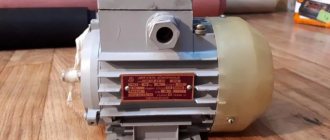
Example of electric motor marking
To start the switch, a time interval is selected at which the current sinusoid has the highest amplitude indicator. The current strength in the third coil “C” is minimal, which is due to the presence of inductive reactance.
When short-circuiting resistance “B” in a common circuit with “C”, an inrush of current is created using a closed contact along the turns of the third winding. The contact itself grows quite quickly, after which it decreases under the influence of a decrease in the voltage amplitude, which smoothly tends to zero.
Also, a so-called time shift is formed in the system, which is marked ϕ. Thanks to the formed shear angle, a single strong magnetized flux is generated, which sets the rotor in motion.
The current supply in the third coil “C” during the operation of the switch differs from the voltage form implemented in a harmonic sine wave. Despite this, it does not in any way affect the generation of torque on the motor shaft. When a half-wave transitions from a sine wave to the sphere of “minus” indicators, the situation repeats itself, and the power unit itself spins further than before.
Useful tips
- Capacitors always retain high voltage at their terminals, so these devices should always be fenced.
- When working with these elements, it is necessary to pre-discharge them.
- An electric motor with a power of more than 3.0 kW cannot be connected to an alternating current network. Machines and other devices included in the wiring diagram will burn out.
- The operating voltage of paper capacitors is half the nominal voltage indicated on their case.
Single phase
Now let's talk about another type of asynchronous electric motors.
These are single phase AC capacitor machines. They have two windings, of which, after starting, only one of them works. Such engines have their own characteristics. Let's look at them using the example of the ABE-071-4C model. In another way, they are also called split-phase asynchronous motors. They have another auxiliary winding wound on the stator, offset relative to the main one. Starting is carried out using a phase-shifting capacitor.
Diagram of a single-phase asynchronous motor
From the diagram it can be seen that AVE electric machines differ from their three-phase counterparts, as well as from single-phase collector units.
Always carefully read what is written on the tag! The fact that three wires are output does not mean at all that it is for a 380 V connection. Just burn the good stuff!
Single-phase asynchronous electric motors
Device and principle of operation
The power of such a single-phase 220V motor can, depending on the design, range from 5 W to 10 kW. Its rotor is usually a short-circuited winding (“squirrel cage”) - copper or aluminum rods closed at the ends.
Such a single-phase motor usually has two windings offset by 90° relative to each other. The working (main) one occupies most of the stator slots, and the starting (auxiliary) one occupies the remaining part. And it is called single-phase because it has only one working winding.
Alternating current flowing through the main winding creates a periodically changing magnetic field. It can be considered to consist of two circular ones with the same amplitude, rotating towards each other.
According to the law of electromagnetic induction, in closed turns of the rotor, a changing magnetic flux creates an induced current that interacts with the field that generates it. If the rotor is stationary, the moments of the forces acting on it are the same, as a result of which the rotor remains stationary.
If the rotor begins to rotate, then the equality of the moments of these forces will be violated, since the sliding of its turns relative to the rotating magnetic fields will become different. As a consequence, the Ampere force acting on the rotor turns from the direct magnetic field will be significantly greater than from the reverse one.
An induced current in the rotor turns can only arise when they cross the magnetic field lines. And to do this, they must rotate at a speed slightly lower than the field rotation frequency (with one pair of poles - 3000 rpm). Hence the name that such electric motors received, asynchronous.
As the mechanical load increases, the rotation speed decreases and the magnitude of the induction current in the rotor turns increases. As a result, both the mechanical power of the engine and the power of the alternating current it consumes increase.
Startup and connection diagram
It is clear that it is inconvenient to manually spin the rotor every time you start the electric motor. The starting winding is used to create the initial starting torque. Since it makes a right angle with the working winding, in order to create a rotating magnetic field, the current in it must be shifted in phase relative to the current in the working winding by also 90°.
This can be achieved by including a phase-shifting element in its power supply circuit. A resistor or inductor cannot provide a phase shift of 90°, so in most situations it is logical to use a capacitor as a phase-shifting element. In this case, a single-phase electric motor has the best starting properties.
When the phase-shifting element is a capacitor, single-phase electric motors can be structurally as follows:
- with a starting capacitor (Fig. a);
- with starting and working (Fig. b);
- only with a working capacitor (Fig. c).
The first (most common) option involves connecting the starting winding with a capacitor for a short time during the start-up, after which they are turned off. It can be implemented using a time relay, or even simply by closing the circuit while pressing the start button. This starting circuit is characterized by a relatively small starting current, but in rated mode the characteristics are low. The reason is that the stator field is elliptical (it is stronger in the pole direction than in the perpendicular direction).
A circuit with a working, always-on capacitor works better in nominal mode, but has mediocre starting characteristics. The option with a starting and running capacitor is intermediate between the two described above. Calculating the values of their capacitances is relatively simple: for the working one 0.75 μF per 1 kW of power, for the starting one - 2.5 times more.
Connecting phase-shifting capacitors
Three phase current
For normal operation, an electric machine requires starting and operating tanks.
Selecting the value of the working capacitor
There are different formulas for determining the required capacity of a working capacitor, taking into account the rated current, cosφ and other parameters, but most often you simply take 7 μF per 100 W or 70 μF per 1 kW of power.
After assembling the circuit, it is advisable to connect an ammeter in series with the machine and, by increasing and decreasing the working capacity, achieve the minimum value of the instrument readings.
Important! Working capacitors are used for alternating voltages of at least 300V.
Selection and connection of starting capacitors
Starting using only working phase-shifting capacitors takes a long time, and with a significant torque on the machine shaft it is impossible. To facilitate the start-up and reduce its duration during the acceleration period of the electric machine, starting tanks are connected parallel to the workers. They are selected 2-3 times more than workers. The rated voltage is also more than 300V. The start-up takes a few seconds, so it is possible to connect electrolytic capacitors.
Engine operation 380 volts
Such motors are called three-phase. They have many advantages over typical household ones and are widely used by industry. The advantages relate to high power and efficiency. It is in three-phase motors that it is possible to do without starting windings and capacitors if there is appropriate power. The design manages to eliminate unnecessary elements. Start-up protection relay of the refrigerator, which clearly monitors the integrity and operating time of the starting winding. Three-phase motors do not need home-grown tricks.
A simple example of three phase operation
Why is this happening? The presence of three phases makes it possible to create a rotating electromagnetic field inside the stator without additional tricks. Let's look at the drawing. For the sake of simplicity, a rotor is shown equipped with two poles; the stator contains a coil per AC phase. The configurations of typical 380 volt motors are more complex; simplification will not hurt to explain the essence of the processes occurring inside.
The figure in blue shows negatively charged fields, in red - positive ones. At the initial moment, the stator is unsigned, the three coils are white. The rotor in our assumption is made of permanent magnets, painted and in an arbitrary position. There are only two poles. Next we move according to the diagrams:
- The first picture gives phase B a negative sign, the other two are slightly positively charged (about a third of the amplitude), schematically shown in pale pink. The positive pole of the rotor moved towards coil B. The weak positive field A-C attracted the south pole of the rotor. Since the charge level is the same, the center of the pole is exactly in the middle.
- At the next moment of time (after 60 degrees, 3.3 ms) the south pole appears on phase A of the stator. The rotor rotates 60 degrees clockwise. The weak negative fields of phases B and C hold the positive pole of the rotor between them.
- At this point in time, the north pole of the stator is located at phase C, the rotor continues to rotate another 60 degrees. The further picture should be clear.
Three-phase electric motor
As a result of the correct distribution of the three phases, the stator field rotates, dragging the rotor. The speed does not match the network 50 Hz. There are more stator windings, the number of rotor poles is different. In addition, there is the phenomenon of slipping depending on the voltage amplitude and many other factors. Nuances are used to regulate the speed of rotation of the motor shaft. We have come close to solving the problem of 380 volt voltage. It is formed by three phases with an effective voltage value of 220 volts (as in a socket). Take the difference between any two at an arbitrary point in time, the value exceeds the specified value.
It turns out 380 volts. A three-phase motor uses three voltages to operate with an effective value of 220 volts, the shift between any is 120 degrees. Can be easily seen from the graph in our figure. This is why many are tempted to use the equipment at home, running it using the single phase supplied by the socket. It is impossible to do it directly, as should be clear, you have to invent tricks. The simplest one is the use of a capacitor. The passage of the capacitance changes the phase of the voltage by 90 degrees. The difference is less than 120, which we wanted to get ideally.
In practice, connecting an electric motor through a capacitor works fine. True, to implement the idea you will have to tinker a little.
Let's first consider how a three-phase motor is connected to a 380V network.
Three-phase motors come with either three terminals - for connection to a star only - or with six connections, with the ability to select a circuit - star or delta. The classic scheme can be seen in the figure. Here in the picture on the left there is a star connection. The photo on the right shows how it looks on a real engine frame.
It can be seen that for this it is necessary to install special jumpers on the required pins. These jumpers come with the motor. In the case where there are only 3 terminals, the star connection is already made inside the motor housing. In this case, it is simply impossible to change the winding connection diagram.
Some say that they did this to prevent workers from stealing units from home for their own needs. Be that as it may, such engine options can be successfully used for garage purposes, but their power will be noticeably lower than those connected by a triangle.
How the scheme works
When K1 is turned on using a time relay, K3 is turned on. The three-phase motor, connected in a star configuration, operates with more power than usual. After some time, the contacts of relay K3 open, but K2 starts. Now the motor operation pattern is “triangle”, and its power becomes less.
When a power cut is required, K1 is started. The pattern is repeated in subsequent cycles.
A very complex connection requires skill and is not recommended for beginners.
Reconnection from 380 volts to 220
It is very important to understand how a three-phase electric motor is connected to a 220V network. To connect a three-phase motor to 220V, note that it has six terminals, which corresponds to three windings. Using a tester, the wires are pinged to find the coils. We connect their ends in twos - we get a “triangle” connection (and three ends).
To begin with, we connect the two ends of the network wire (220 V) to any two ends of our “triangle”. The remaining end (the remaining pair of twisted coil wires) is connected to the end of the capacitor, and the remaining capacitor wire is also connected to one of the ends of the power wire and coils.
Whether we choose one or the other will depend on which direction the engine starts to rotate. Having completed all the above steps, we start the engine by applying 220 V to it.
The electric motor should work. If this does not happen, or it does not reach the required power, you need to return to the first stage to swap the wires, i.e. reconnect the windings.
If, when turned on, the motor hums but does not spin, you need to additionally install (via a button) a capacitor. At the moment of starting, it will give the engine a push, forcing it to spin.
Video: How to connect an electric motor from 380 to 220
Calling, i.e. resistance measurement is carried out by a tester. If this is not available, you can use a battery and a regular flashlight lamp: the identified wires are connected to the circuit in series with the lamp. If the ends of one winding are found, the lamp lights up.
It is much more difficult to determine the beginning and ends of the windings. You can't do without a voltmeter with an arrow.
You will need to connect a battery to the winding, and a voltmeter to the other.
By breaking the contact of the wire with the battery, observe whether the arrow deviates and in which direction. The same actions are carried out with the remaining windings, changing the polarity if necessary. Make sure that the arrow deviates in the same direction as during the first measurement.