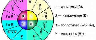
The nameplates of many electric motors (electric motors and other devices) indicate the active power in W and cosφ / or λ / or PF. See below for what's what.
We assume that the alternating voltage in the network is sinusoidal - ordinary, although all the arguments below are also true for all harmonics separately of other periodic voltages.
- angle φ is the angle between the voltage phase and the current phase, also called the phase shift, while if the current lags behind the voltage, the phase shift is considered positive, if it is ahead of it, then negative
- the value of sin φ for φ values from 0 to plus 90° is a positive value. The sin φ value for φ values from 0 to -90° is a negative value
- if sin φ>0, then the load is active-inductive in nature (electric motors, transformers, coils.) - the current lags behind the voltage
- if sin φ
- All relations between P, S and Q are determined by the Pythagorean theorem and elementary trigonometric identities for a right triangle
Reactive power Q (reactive power) is measured in reactive volt-amperes (var, var ) and is electromagnetic power that is stored in the receiver and sent back to the network by the oscillating circuit of the system. Reactive power ideally does not perform work, i.e. The title is misleading. It’s easy to guess by looking at the picture that:
The very concept of active and reactive power is relevant for alternating current devices (receivers). It is of little relevance = never mentioned for DC receivers due to the smallness (minuscule) of the corresponding effects associated only with transient processes when turning on/off.
Any system, as is known, has capacitance and inductance = is a kind of oscillating circuit. Alternating current in one phase pumps the electromagnetic field of this circuit with energy, and in the opposite phase this energy goes back to the generator (to the network). This causes 3 problems in the Russian Federation ( for the energy supplier! )
- Although theoretically, with zero transmission resistance, no generator power is wasted on generating reactive power, but in practice, transmitting reactive power through the network requires additional, active generator power (transmission losses).
- The network must pass both active and reactive currents, i.e. have a margin of throughput characteristics.
- The generator could, by delivering the same current and voltage, supply more active power to the electricity consumer.
Naturally, I would like to introduce a value that would characterize the degree of linearity of the load. And this value is introduced under the name power factor (“cosine phi”, power factor, PF), as the ratio of active power to total power, naturally in 2 types at once, in the Russian Federation it is:
What kind of lighting do you prefer?
Built-in Chandelier
Expert opinion
It-Technology, Electrical power and electronics specialist
Ask questions to the “Specialist for modernization of energy generation systems”
Power factor (cos φ, cosine phi), Total (apparent), active and reactive power of an electric motor and more. Power factor for a three-phase electric motor. tables Reactive power Q reactive power is measured in volt-amperes reactive var, var and this is the electromagnetic power that is stored and transmitted back to the network by the oscillating circuit of the system. Ask, I'm in touch!
What does the angle φ express?
φ
—
the angle
between the voltage and current vectors; - for symmetrical or almost symmetrical loads of four-wire systems.
Interesting materials:
How to connect a wireless headset to ps3? How to connect a wireless keyboard to Xbox One? How to connect a wireless mouse without an adapter? How to connect a wireless mouse to a tablet? How to connect a wireless network on Windows 8? How to connect AirPods wireless headphones to Android? How to connect wireless headphones via bluetooth? How to connect JBL wireless headphones to Samsung? How to connect JBL Tune 120 wireless headphones? How to connect wireless headphones to Android?
EQUIPMENT TECHNOLOGY DEVELOPMENT
Power factor (cos φ) is a parameter characterizing the distortion of the shape of the current consumed from the alternating current mains. An important indicator of the electricity consumer. In many ways, it determines the requirements for the power supply network. The losses in the wires and the internal resistance of the network depend on it.
In DC circuits, power, however, like all other parameters, does not change its value over a certain period of time. Therefore, with constant current, there is a single concept of electrical power as the product of current and voltage values.
With alternating current, current and voltage values constantly change over time. The power also changes. Therefore, the concept of instantaneous power is introduced.
Instant power.
Instantaneous power is the product of the instantaneous circuit voltage and the instantaneous current. In practice, power is related to heat generation, mechanical work, etc. And these phenomena are inertial in nature. Therefore, the concept of instantaneous power has no practical meaning, but is used for calculations and understanding of ongoing processes.
Effective values of current and voltage.
RMS values of current and voltage are used to evaluate and calculate AC circuits.
The effective value of alternating current is defined as the value of such an equivalent direct current, which, passing through the same active resistance as alternating current, releases the same amount of heat over a period. Mathematically, the effective value is defined as the root mean square over the period.
AC voltmeters and ammeters show actual values. All operations for thermal calculations occur in the same way as for direct current, only using effective values. But this is not always correct.
Full power.
The apparent power is calculated as the product of the effective values of the current and voltage of the circuit.
S=U*I
In the case of a sinusoidal shape of current and voltage, as well as the absence of a phase shift, all the total power is released to the load. Calculations for alternating current correspond to the analysis of direct current circuits, only the effective values of current and voltage are used.
Apparent power actually shows the requirements for the electrical network. It is measured in VA, not in W.
Reactive power.
As soon as reactive elements (inductance and capacitance) appear in the AC circuit, everything changes. Reactive elements have the ability to accumulate energy and release it back into the circuit. Reactive power appears.
Reactive power is not released at the load and does not create useful work. It accumulates on reactive load elements (capacitors, inductors), and then returns back to the supply network. It is clear that it returns with losses on the wires, on the internal resistance of the supply network, etc. Therefore, in any power system they strive to reduce reactive power to a minimum.
Reactive power can be either positive (for inductive circuits) or negative (for a capacitive component).
The unit of measurement is volt-ampere reactive (VAR).
Active power.
Active power remains on the load. She does useful work. Active power is the average value of instantaneous power over a period.
Basic relationships between parameters.
The total power in alternating current circuits is equal to the square root of the sum of the squares of the active and reactive powers.
S = √ (P2 + Q2)
Active power is calculated as:
P = I * U * cos φ
I and U are the effective values of current and voltage.
Or:
P = S * cos φ
Those. active and apparent power are related through a coefficient - cos φ.
cos φ is the cosine of the shift angle between the supply voltage and the current consumed by the load. This relationship is only true for sinusoidal current and voltage waveforms. At cos φ = 1, the active power at the load is equal to the total power. All energy from the supply network is used for useful work. This happens only on a purely active load, without a reactive component.
cos φ is the power factor (PF) for alternating circuits with sinusoidal current and voltage.
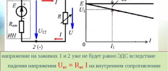
But many energy consumers not only shift the phase, but distort the shape of the current. An example would be a power supply with a transformerless input. This is an equivalent circuit for connecting it to the power supply.
In such devices, the supply voltage is rectified and smoothed by a large capacitor. The resulting low-ripple DC voltage is used for further conversion.
For the supply network, this circuit represents an active-capacitive load. But rectifier bridge diodes have a nonlinear characteristic. At the beginning and end of the period they are closed and the load is switched off. And in the middle of the period, the diodes open and, in addition to the active load, a significant capacity of the smoothing filter is connected to the network. As a result, the current has a distorted shape, shown in the figure.
This is one of the most unpleasant types of load, but also the most common. All household appliances (TVs, computers...) present this type of load.
Power factor (PF) in alternating circuits with a distorted current waveform is defined as the ratio of active power to total power.
λ = P/S
The following diagrams illustrate how CM affects the performance of electricity consumers.
This figure shows waveforms of a purely resistive load. There is no phase shift, cos φ = 1, all energy from the network goes into active power at the load.
The second picture shows the extreme, worst option.
The phase shift between current and voltage is 90°, cos φ = 0. It can be seen that the instantaneous power diagram is located symmetrically with respect to 0. The average active power is 0. Of course, there are no devices with cos φ = 0 in practice, but there are any number of intermediate options. For example, the transformerless power supply given as an example above has a KM of 0.6 - 0.7.
The significance of CM can be shown by simple calculations.
Two electricity consumers with the same active (net) power. The first one has cos φ = 1, and the second one has 0.5. This means that the second consumer consumes twice as much current from the network as the first. Because the dependence of losses in wires on current is quadratic in nature (P = I2 * R), then losses on the active resistance of wires in the second case will be 4 times greater. Larger gauge wires will be required.
For powerful loads and long power lines, high KM is especially important.
Power factor measurement.
To measure cos φ, special devices are used - phase meters. They are used in networks with sinusoidal current consumption, without distortion.
To measure CM for loads that distort current, the following technique is usually used.
Power factor measurement circuit.
It is necessary to calculate the total power as the product of the voltmeter and ammeter readings.
S=U*I
Now you need to divide the active power (wattmeter readings) by the total.
λ = P/S
If you don't have a wattmeter, you can use an electricity meter.
To do this, you need to measure the time of 10 calibration pulses (flashing LEDs on the meter body). Calculate the time of the period of one pulse (divide by 10). Knowing the meter coefficient (usually 3200 pulses per kW), you can calculate the active power of the load. Considering that electricity meters have an accuracy class of 1.0, the measurement will be quite accurate.
Power factor correction.
To increase the power factor, there are special devices - power factor correctors (PFC). They can be passive and active.
For passive correction of the CM, a choke is connected in series to the power circuit. This solution is often used for cathodic protection transformer stations. But this is out of desperation. There are no other solutions for transformer stations. The choke required is of enormous size, no less than the power transformer of the station. The size, weight, and price of the station almost double, but the power factor can only be raised to 0.85.
In inverter stations of cathodic protection without a power corrector (rectifier-capacitive load, the example was above) CM is about 0.6 - 0.7. To increase it, special electronic modules are used - active power factor correctors. Their circuits are built on the principle of a boost pulse converter. Special control microcircuits monitor the shape of the consumption current and control the converter switch in such a way that it becomes sinusoidal. At the output of the active PFC, a constant voltage of 380 - 400 V is generated. Therefore, it is impossible to use them with transformers.
Active correctors increase KM to 0.95 - 0.99.
An example of a 2000 W active PFC for an inverter cathodic protection station of the “TIELLA” series.
I will devote a separate article to the circuit design of active PFCs.
Support the project
0
Author of the publication
offline 15 hours
Edward
236
Comments: 1790Publications: 183Registration: 13-12-2015
Formulas for squares of trigonometric functions
05.1)Sine square
square sine formula05.2)Cosine Squared
square cosine formula05.3)Tangent squared
tangent square formula05.4)Squared cotangent
cotangent square formula05.5)Sine square of half angle
formula for square sine of half angle05.6)Squared cosine of half angle
formula for squared cosine of half angle05.7)Square of the tangent of a half angle
formula for squared tangent of half angle05.8)Formulas for cubes of trigonometric functions
formula for the squared cotangent of a half angle06)Relationship between tangent and cotangent
\[ tg \alpha \cdot ctg \alpha=1 \]
This identity is valid only for angles \( \alpha \) that are different from \( \dfrac{\pi}{2} z \). Otherwise, either cotangent or tangent will not be determined.
Based on the above points, we obtain that \( tg \alpha = \dfrac{y}{x} \), and \( ctg \alpha=\dfrac{x}{y} \). It follows that \( tg \alpha \cdot ctg \alpha = \dfrac{y}{x} \cdot \dfrac{x}{y}=1 \). Thus, the tangent and cotangent of the same angle at which they make sense are mutually inverse numbers.
General formulas
14.1)Formula for reducing the nth even power of sine
formula formula formula for reducing n even power of sine14.2)Formula for reducing the nth even power of cosine
formula for reducing the nth even power of cosine14.3)Formula for reducing the nth odd degree of sine
formula for reducing the nth odd power of sine14.4)Formula for reducing the nth odd power of cosine
formula for reducing the nth odd power of cosineAssistance for the development of the premierdevelopment.ru project
Send mail and we will know that we are moving in the right direction. Thank you for stopping by!
I. For reference:
sine of angle α - sin(α) is the ratio of the opposite side of angle α to the hypotenuse. cosine of angle α - cos(α) is the ratio of the leg adjacent to angle α to the hypotenuse. tangent of angle α - tan(α) is the ratio of the opposite side to the angle α to the adjacent side; an equivalent definition is the ratio of the sine of an angle α to the cosine of the same angle - sin(α)/cos(α). cotangent of angle α - ctg(α) the ratio of the side adjacent to angle α to the opposite; an equivalent definition is the ratio of the cosine of an angle α to the sine of the same angle - cos(α)/sin(α).
Other trigonometric functions:
secant - sec(α) = 1/cos(α). cosecant - cosec(α) = 1/sin(α).
To derive formulas for cosine, sine, tangent or cotangent of multiple (4+) angles, it is enough to write them according to the formulas of the corresponding cosine, sine, tangent or cotangent of the sum, or reduce them to the previous cases, reducing them to formulas for triple and double angles.
Far from electrical engineering, but a very clear example
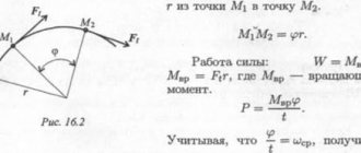
To explain how the angle ϕ (or rather its cosine) affects power, let’s consider an example that has nothing to do with electrical engineering. Let's say we need to move a cart standing on rails. To make this operation more convenient, we attach a rope to its front part.
If we pull the rope straight ahead in the direction of travel, then we need to apply a fairly small force to move the cart. However, if you are on the side of the rails and pull the rope to the side, then to move the cart at the same speed it will be necessary to apply much more force. Moreover, the larger the angle (ϕ) between the direction of movement and the applied force, the more “power” will be required from us.
Conclusion! That is, an increase in the angle ϕ leads to an increase in the energy we consume (with the same work performed).
Correction of λ in everyday life
When it comes to electronics, there are regulations that limit the harmonics introduced into the network by household appliances (PCs, TVs, etc.). Although there are no international standards that directly regulate power factor, power factor correction automatically reduces harmonic distortion. Thus, for power supply designers, the main reason for increasing the cosine phi of a transformer is to satisfy a specific harmonic content requirement, even if it may not provide any direct benefit to either the manufacturer or the user.
In everyday life, low λ reduces the throughput of conductors and circuit breakers. In addition, contrary to popular belief among those unfamiliar with basic electrical engineering, homeowners and consumers do not benefit from power factor correction.
What is PF?
Power factor is a complex indicator characterizing energy losses in the electrical network caused by phase and nonlinear distortions of current and voltage in the load. … The lower the power factor of a load, the more that load puts stress on the source and wires.
Interesting materials:
How much was the pound worth in the 19th century? How much does 1 km according to Plato cost? How much does 1 cubic meter of cement cost? How much does analgin cost in tablets? How much does badger fat cost? How much does a ticket from Moscow to Seychelles cost? How much does a ticket to a Barça match cost? How much does the Boeing 737 MAX cost? How much does the display cost on Samsung A 50? How much does a Range Rover jeep cost?
Active and passive compensation
Active reactive power compensation uses active closed-loop electronic circuits that smooth the shape of the rectified current curve.
Nonlinear devices generate harmonic oscillations with a frequency ƒ=1/(2π√LC). If it coincides with one of the harmonics, it will amplify, which can lead to various consequences, including catastrophic ones. To avoid this, a small inductor is connected in series with the compensating capacitor, which forms the so-called. shunt harmonic suppression filter.
Content
8. The minimum values of the reactive power factor generated during hours of low daily loads of the electrical network, with the exception of hours of low daily loads of the electrical network applied during periods of consumer participation in reactive power regulation, are set equal to zero.
Expert opinion
It-Technology, Electrical power and electronics specialist
Ask questions to the “Specialist for modernization of energy generation systems”
Active and passive compensation The procedure for calculating the ratio of active and reactive power consumption for individual power receiving devices of groups of power receiving devices of electrical energy consumers approved. Ask, I'm in touch!
Nonlinear distortion
Inductors and capacitors are not the only causes of low cosine phi. It is common in electrical engineering when (except for ideal R, L and C) electrical circuits are non-linear, especially due to the presence of active components such as rectifiers. In such circuits, the current I(t) is disproportionate to the voltage V(t), even if the latter is a pure sinusoid, since I(t) will be periodic but not sinusoidal. According to Fourier's theorem, any periodic function is a sum of sine waves with frequencies that are multiples of the original one. These waves are called harmonics. It can be shown that they do not contribute to the transfer of net energy, but increase the current and reduce the coefficient λ. When the voltage is sinusoidal, only the first harmonic I1 will provide real power. However, its magnitude depends on the phase shift between current and voltage. These facts are reflected in the general formula for calculating power factor: λ = (I1/I) × cos(φ). The first term in this equation represents distortion and the second term represents displacement.