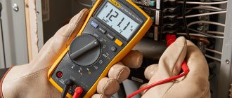
If there is a power failure in a house or apartment, you will need to quickly check the in-house wiring. This will not be difficult when the home technician has a multimeter and knows the basic safety rules for working with voltage.
Testing the wires with a multimeter is performed to determine their suitability, the absence of internal breaks, short circuits in the electrical circuit and determine the resistance of the circuit. The method is the most effective, proven and accurate. The most inexpensive digital model can easily cope with this task. Before testing the wires with a multimeter, a home mechanic must learn how to operate the measuring device and turn off the current on the network being tested.
Which multimeter is preferable to use?
In the case when there is no such device in the house, and the owner is just planning to purchase it, you need to know about the important features of the choice. For home needs, it will be enough to purchase a budget model that has an audible dial tone indication.
On the panel of such a device there is a designation of a diode or sound. When testing for line continuity with this meter, a sound will be heard when the contact is closed.
Strictly speaking, this function is not necessary for testing wires with a multimeter, but it is very convenient and helps to perform testing more efficiently. The fact that the electrical circuit has a break is also indicated by “1” on the display. This means that the resistance between the test leads is significantly greater than the permissible limit. If there is no damage, the display will read around “0”.
Important! Wire resistance “0” is an ideal state and can only be implemented in home networks, and even not very long ones.
Conclusions and useful video on the topic
The videos below provide detailed video instructions for finding a damaged cable.
Video #1. Searching for a cable break using a metal detector:
Video #2. If you have a radio handy, it can also help:
Finding a broken wire is a rather complex and responsible process. It requires attention, accuracy and strict adherence to instructions. Using the methods outlined above, you can find the location of the wire damage and eliminate the defect found.
Please write comments in the block below. Your stories about finding an open circuit in an electrical circuit and how to fix it are interesting. Ask questions, share useful information and photos on the topic of the article.
How to safely ring wiring in an apartment
The work of repairing electrical equipment does not allow amateurism. There is a set of rules clearly established by the state for the safe operation of electrical networks, which allow not only to correctly test the intra-house electrical network, but also to protect the life and health of the performer from possible damage by electricity.
Basic safety rules that a home handyman must follow before wiring:
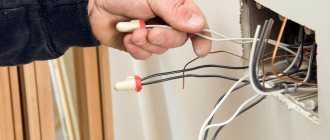
- In order to keep your hands free and the measurement contact more durable, when working with probes, experts advise using specialized clamp tips, which in everyday life are called “crocodiles”.
- Before checking the wiring with a multimeter, it is completely de-energized, including from low-current power sources, for example, batteries. This must be done before determining the phase.
- Before measuring resistance, look to see if there is a capacitor in the circuit being measured. It must first be discharged, otherwise the measuring device may burn out.
- When checking an extended cable, do not touch bare areas with your hands. Since it is disconnected from the power supply, it does not pose a threat to human life, but does affect the accuracy of the measurement.
- When testing a multi-core electrical cable, both ends are first stripped and separated, then the test is carried out alternately using “crocodiles”.
- The tester should not be used in a humid environment.
- It is not allowed to use probes with defects.
- When taking measurements, it is unacceptable to change measuring modes and rearrange the position of switches.
- You cannot check the properties of conductors if their parameters are higher than the permissible limits of the tester.
Important! The rotary lever is always set to the highest value first, to avoid damaging the multimeter. In the future, they gradually move to lower gradations until the readings of the measured value reach 2/3 of the established scale. In this case, the most accurate measurements with minimal error will be provided.
Compliance with safety precautions and rules for working with a multimeter
All electrical work must be carried out in a de-energized room.
It is necessary to connect electrical wires and work with a multimeter, following the safety rules:
- Testing elements that are disconnected from a circuit to prevent them from interfering with the circuit.
- De-energize the circuit by turning off the circuit breakers in the switchboard.
- Discharge capacitors by shorting them to prevent data corruption.
- Take into account the distortion of results from network diodes.
- Leaking current when touching the wires and probe tip with your hands will lead to incorrect results.
- Use crocodile tips at the ends of the meters to ensure reliable contacts.
If the circuit breakers do not work
In this case, all electrical equipment and devices that are powered from this line are checked.
For example, if the lighting in a room stops working or 2 sockets on the wall do not work at the same time, then check the following nodes one by one:
- Turn off the power supply to the house network completely.
- Before checking the resistance, check whether the multimeter is working. This is done by short-circuiting the probes. The display should show “0”. If the readings are slightly different, for example, 0.1, this will indicate that the device has an error.
- Check the serviceability of the light bulb by unscrewing it from the socket. One probe touches the cartridge, and the other touches the end part. A buzzer and meter readings other than “0” and “1” indicate that the device is working.
- Check the wall switch by removing the panel, removing the screws, and removing it from the box. If there are no visible violations, then check the switch with a tester, installing probes on its contacts. The absence of a buzzer indicates that the switch is faulty and needs to be replaced. As a rule, after this the light appears in the room.
Specifics of dialing of some devices
You can use a multimeter not only for cable measurements. Experts use it to measure electrical equipment.
Fuse
Checking the fuse by resistance
Devices in the form of a small box with a thin internal cable prevent overheating and fire of circuit elements. Models without wiring are tested as follows:
- The device is switched to dialing mode.
- The probes are applied to both sides of the fuse.
- When the resistance is 0 Ohm and there is sound, the device works.
- The number 1 appears, there is no sound - the fuse is broken.
Diodes and LEDs
Checking the LED with a tester
The polarity of diodes is represented by a positively charged anode and a negatively charged cathode. For this reason, it only allows current to flow in one direction. When testing, the multimeter is switched to a special mode:
- Probes are placed on anodes and cathodes without reference to color.
- The tester is activated.
- The probes are swapped and the tester is turned on again.
The serviceability of the diode backlight is determined based on the appearance of voltage in the first case and the number 1 in the second.
The polarity of the LED is opposite. It works when there is a plus on the anode and a minus on the cathode. Probes work in a similar way. If the voltage appears and then disappears, the LED is working.
Lamps
After switching the tester to dialing mode:
- Place the first probe on the central contact of the light source.
- Place the second probe on the side contact.
- A malfunction is determined by a buzzer and a 3-200 Ohm indicator.
If the circuit breakers have tripped
This option indicates that there has been a serious failure in the electrical networks of the house, perhaps even a short circuit. Most likely, the wiring has failed, which can be checked by continuity.
To do this, the owner must sequentially complete the following steps:
- Use a screwdriver to disconnect the wire. Usually, it is located below and taken to the side. The “0” wire of this group is usually located at the 0 terminal under the circuit breaker.
- Before finding a fault, remove the light bulb from the socket and then check the lighting line with a multimeter, connecting the 1st probe to “0” and the 2nd to the disconnected wire. When a sound signal appears, the wire is shorted.
- At the top of the room they find and open the panel, disconnect the wires.
- Each pair is checked for the presence of a short circuit.
- After identifying the defective area with a short circuit, it is again tested with a circuit meter on the input panel. If there is a sound from the tweeter, then repairs must be made on the wire from the switchboard to the box. If not, then continue to examine other wires using a similar method.
Searching for electrical wiring for preventive purposes
Usually, electricians or residents start looking for cables running through the apartment when there are problems with the light.
Meanwhile, you should take care of this in other situations:
- Before the planned redevelopment of the apartment. For any manipulations that even affect non-load-bearing structures (for example, when dismantling a partition or moving a doorway), it is important to take into account the location of electrical communications.
- Before installing sconces, hanging pictures or other wall accessories. To carry out such work, it is important to know where the cable is located so as not to stumble upon it when drilling holes or driving nails.
- When purchasing a home. Immediately after purchasing an apartment, it is advisable to draw up a plan for the electrical networks located along the walls and ceiling. On the diagram it is also worth noting the locations of sockets, switches, and junction boxes. Such markings will help when performing major/cosmetic repairs of the apartment, as well as when arranging furniture.
Read also: Small figures made from rubber bands on a slingshot
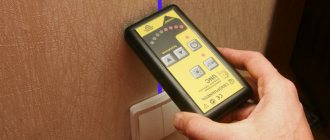
To search for an electrical route, you can use homemade or professional devices, which were described above.
Checking the antenna cable
It should be noted that it is impossible to fully measure the quality of a TV signal with a standard multimeter. On sale you can find a special multimeter that has a built-in frequency meter. In this case, when setting up a specific channel, you can test for compliance between the specified and actual values of this parameter. In other cases, the tester can only be used to measure the antenna cable for resistance and wire integrity.
Important! Before you can test the antenna cable, you will need to have access to both ends. Then you can correctly measure the resistance with a multimeter.
In this case, an ohmmeter is used to determine the actual resistance between the pin and ring pin contacts. If, when checking the cable with a multimeter, the resistance is less than 20 ohms, then it is in good condition. If it shows infinity, then there is a break in the antenna cable. A resistance value of zero or close to it indicates a high risk of short circuit occurrence.
Causes of malfunctions
If the operating rules for electrical communications are observed, they can serve regularly for decades. But in practice, damage to electrical networks is quite common, which can be caused by various reasons.
These factors include:
- Long-term operation of the cable . Wiring can function flawlessly for many years, but after a certain time limit it begins to deteriorate. In this case, twists scatter in the network and leaks appear, which regularly knock out the RCD (its absence affects the increase in leaks). Sooner or later, such violations lead to interruptions, and then to a complete cessation of the power supply.
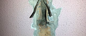
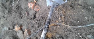
- Mechanical damage . Without knowing the layout of electrical networks, when drilling holes and driving nails into the wall, you can easily touch a wire, causing it to break and sometimes short circuit. Sometimes minor mechanical damage has a delayed effect: in this case, the integrity of the core may not be damaged immediately, but after several months or even a year.
- Defective wire or poorly executed electrical installation . Damaged cables tend to become constantly hot, which can have fatal consequences. After a sudden power surge, such wires may break.
- Incorrect use of adapters . Electrical wiring malfunctions can be caused by improper use of extension cords or tees. This can happen if several high-power household appliances are connected to the device, for example, a washing machine and dishwasher.
If the adapter is used incorrectly, the cables that come from it are subject to overheating and increased stress, which can lead to melting of the insulation.
In all cases, it is necessary to identify the location of the cable damage in order to immediately repair the damage.
How to check the intercom wire
The intercom may not work due to incorrect switching or a damaged communication line. In order to restore functionality, you will need to determine the breakdown points and correctly establish their polarity.
The need to test this network arises if during the installation process “+” and “−” are mixed up and you need to correctly identify them with a tester. To do this, select the constant voltage mode, setting the indicator to 20 V. The black probe (–) is connected to COM, and the red probe (+) to the V, mA socket.
Then the probes are pressed to the wire or to the contact group. If the meter display shows values without unnecessary icons, the poles are selected correctly. If a minus appears on it, the wires are mixed up, they need to be swapped.
The test is carried out for each pair of wires. The multimeter readings will indicate the condition of the intercom wire:
- Operating condition, 600–800 Ohms, when changing probes, it tends to infinity;
- 1200–1300 Ohm, the line is broken or there is a failure in the intercom handset;
- 0–260 Ohm - short circuit on the communication line.
Testing electrical wires and cables at the installation stage
Installing new home wiring is always associated with certain difficulties, due to which the integrity of the conductors may be compromised even before the main line is used.
The new line is most often laid inside the grooves, or simply on top of the wall, which is then covered with a layer of plaster and subjected to other finishing work. The initial check of the electrical wiring is carried out before the groove is sealed or the wall is plastered.
If the master is too lazy to do this, then it is possible that, after an unsuccessful attempt to turn on the light or use the socket, he will have to chisel the plaster or open a groove in the thickness of the wall.
A wire break at the initial stage can occur due to the fault of both electricians and finishers. To avoid unpleasant consequences and unnecessary work, it is necessary to lay the electrical line according to a diagram drawn up in advance. Before burying wires in the wall, you need to check the electrical wiring for breaks.
How can you make sure the wiring is working properly?
First of all, you need to make sure that the phase and neutral cables, as well as the ground wire, are not in contact with each other - that is, there is no short circuit. If the quality of the conductor insulation leaves much to be desired, then under the influence of high voltage it can be damaged, which will most likely lead to a short circuit. Therefore, when buying an electrical wire, you should not save too much and purchase the cable, focusing on the lowest price. If you doubt the integrity of the insulating layer, check the line with a megohmmeter.
Having laid the line, you should not seal the groove and plaster the wall without first inspecting the surface of the cable along its entire length to ensure there are no mechanical damages.
If the line is not closed, and a visual inspection reveals no damage, it is called for a break.
How to check the wiring during installation is shown in the following video:
Checking wiring integrity using improvised means
If the home technician does not have a multimeter, and the wiring needs to be checked urgently, then you can use improvised means. Before wiring electrical wiring using improvised means, you will need:
- Standard 4.5 V square battery;
- mini light bulb 3.5 V;
- a pair of mounting wires and an alligator clip.
The simplest circuit is assembled on their basis. If you connect it to the ends of the wire under test and the light comes on, then the line is working. Otherwise, the conductor has a break.
Thus, we can draw a line. For a home handyman, if necessary, it will not be difficult to test all the wires located in the house and apartment with a multimeter: lighting lines, intercom and TV cables. The main thing is that before checking the integrity, choose the right measurement interval correctly and adhere to safety rules when working on electrical installations.
Finding the exact location
Having identified the approximate location where the broken wire is located, they begin a thorough search. You can find the exact location of the breakdown in different ways.
Opening walls during renovation
Opening up old electrical wiring is the best way to check it.
The simplest and most effective way to check the condition of wiring and eliminate tears is to completely clean the walls of finishing materials. Only in this case can you familiarize yourself in detail with the condition of the grooves, which were made specifically for hidden wiring. They differ from other surfaces in color, and several layers of putty are additionally applied to them.
This method is advisable only during a major overhaul, accompanied by the complete dismantling of all decorative coatings.
Logical search methods
Patch wiring lines are usually located above the outlets
If the owner of the living space does not have a diagram of the electrical network, it can be recreated using logical methods. You should familiarize yourself with the basic principles of laying electrical communications:
- Most often, wiring is carried out at intervals of 10-15 cm from the ceiling or floor (the first option is more common).
- Installation of electrical communications is carried out strictly along vertical and horizontal grooves. Errors are possible, but small.
- Communication lines that are located above switches and sockets are always laid straight up. In these areas, hammering nails and using drills and hammer drills is prohibited.
DC current measurement
This circuit measures direct current (DC). A number of devices, for example, the DT 830V, are used to measure exclusively DCA current. When measuring current, the device is used as an ammeter with a parallel connection to the object. Procedure for determining electric current:
- Probe connections: black - COM socket, red - VΩmA socket (up to 200 mA) and switch on the DCA icon, 10A connector (200 mA - 10 A) and MMA switch lever for 10A sector. When in doubt, measurements should begin with the highest scale point. Connect the MM to the measuring circuit and turn it on, set the switch to the desired position, break the electrical circuit into which we connect: the red cable (V) to the positive pole of the power source, and the black wire (COM) to the negative. The display shows the current current value.
- You must be extremely careful; if the device is mistakenly connected in parallel in voltmeter mode, not only the fuse and the device itself may fail.
- You cannot measure large currents in a multimeter switch set to 200 mA, otherwise the MM fuse will fail (it will need to be replaced with a 200 mA, 250 V). The 10A multimeter input is generally not protected by any fuse! You need to measure a large current very quickly and you cannot keep the MM turned on for a long period, otherwise a real failure of the device may occur. Many device manufacturers recommend measuring current more than 5A for about 15 seconds.
Read also: Service life of a gas reducer on a cylinder
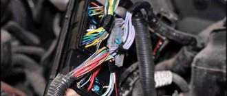
Scheme of connecting a computer to a UTP network using a twisted pair cable
To check a twisted-pair cable, it is advisable to competently imagine the electrical diagram of how a twisted-pair cable connects a computer’s network card to other devices, a hub, a switch or another computer. The figure shows a diagram of a section of the network connecting a computer to active equipment, a hub or switch.
To check the twisted pair cable, the part of the network card or hub circuit to which the RJ-45 twisted pair cable connector is connected is of interest. As you can see, each pair is connected to the transformer in a symmetrical circuit (a tap is made from the middle of the transformer winding, which is connected to a common wire, sometimes through a resistor or capacitor). Thanks to this connection, all induced noise in the cable arrives at the input in antiphase and is mutually destroyed, while the useful signal arrives in phase and its magnitude does not change. The transformer circuit has another advantage: it protects active equipment from short circuits and entanglement of wires in a twisted pair cable when connected.