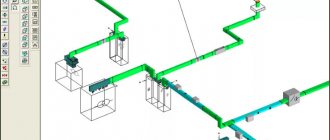
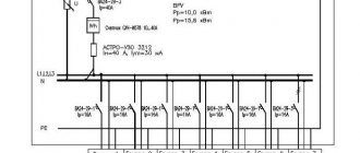
The power supply system (SPS) combines sources, systems for conversion, transmission, and distribution of electricity. Electricity receivers (consumers) are not included in the SES. Power supply systems for industrial enterprises are based on electrical installations that are needed to provide consumers with electrical energy. The consumer can be an electrical receiver or another unit that converts electrical energy into another type of energy. There may also be several of these mechanisms. In this case, they are combined into one technological group and placed in a separate space.
The power supply of industrial enterprises is built on the basis of supply, distribution, transformer, converter substations, as well as on cable, overhead networks, and conductors (low and high voltage) connecting them. The design of power supply for industrial enterprises must take into account the most important requirements that determine:
- reliability;
- convenience;
- safety;
- ensuring the required quantity/quality of energy;
- uninterrupted supply of electrical energy in normal mode and after an emergency;
- cost-effectiveness of energy, materials and equipment.
It is possible to comply with the above requirements by using mutual redundancy of enterprise paths and consolidation of power supply to industrial and municipal (as well as rural) consumers. At the time of construction of an enterprise’s own power station, it is necessary to take into account nearby energy consumers (off-site).
Receivers providing power supply to industrial facilities
- 1 Receivers providing power supply to industrial facilities
- 2 Power supply of industrial buildings. Voltage
- 3 Power supply diagrams for industrial enterprises
- 4 Power supply to industrial enterprises and installations in unfavorable climatic conditions
Since electrical networks and substations are elements of the overall structure of the enterprise, they must be coordinated with technological and construction parts, as well as with the building plan. For example, large enterprises of non-ferrous and ferrous metallurgy have high requirements for reliable and high-quality power supply. They are distinguished by high values of the total installed power of electrical receivers, which can reach 1700-2000 MW.
Electrical receivers can be divided into 3 categories:
1. Electrical receivers that, due to interruptions in power supply, may pose a danger to people, cause damage to equipment, products, etc. Such receivers must be powered from two separate sources. An interruption in power supply is possible only for the period of automatic switching on of the reserve. Examples: production steam boiler houses, blast furnace shops, cupola drives, critical pumping stations, casting cranes, etc.
2. Electrical receivers, interruption in operation of which is associated with undersupply of products, downtime of workers, machinery, and transport. Power interruptions are acceptable for the time required to manually switch on the reserve.
3. Other electrical receivers that are allowed to have a power supply interruption for the duration of repairs (no more than one day). For example, auxiliary workshops, non-critical warehouses, non-serial production workshops, etc.
In order to correctly solve reliability issues, it is necessary to accurately establish the modes that arise during an accident and after it. Emergency mode is a temporary mode that occurs due to a disruption in the acceptable operation of the power supply system or its individual elements. Post-emergency mode is a mode after the elimination of an accident, which lasts until normal operation is completely restored.
It is obvious that the power supply system must be built in such a way that, in a post-emergency mode, it can ensure the functioning of the main production facilities of an industrial enterprise (after the necessary reconnections). In post-emergency mode, interruptions in the power supply to receivers of the third and partly second categories are allowed for a short time.
Requirements for electrical networks of industrial facilities
In addition to the above principles of power supply to industrial enterprises (uninterruption, efficiency, flexibility, proximity to power sources, the minimum number of transformation stages, the use of reliable backbone circuits, etc.), there are also certain regulatory requirements for the electrical networks of industrial facilities.
In industrial enterprises, the power source can be an electrical station from the central power supply system or the enterprise's own station. An own power plant is necessary when there is a large energy consumption, when there are special requirements for the reliability of the power supply system, and when the enterprise is remote from the power systems.
Power supply requirements:
- At enterprises with electrical receivers of categories I and II there must be two or more independent mutually redundant power sources.
- For electrical receivers of special group I category, a third independent power source must be provided.
- Energy-intensive enterprises should be powered from the power grid at a voltage of 110 or 220 kV.
- Enterprises with a light load can operate at voltages of 6, 10 and less often 35 kV.
- At low loads, a voltage of 0.4 kV from the power grid or a neighboring enterprise is sufficient.
- The distribution network of industrial enterprises must operate at a voltage of 10 kV, in some cases - 6 kV, and for energy-intensive enterprises - at a voltage of 110 kV.
With compact placement of electricity receivers, there can be only one receiving point. Two collection points are required under the following conditions:
- if the enterprise has two or more relatively powerful separate groups of consumers;
- with increased requirements for the reliability of power supply for category I electrical receivers;
- during the phased development of the enterprise to power the second-stage loads.
The electrical requirements for various types of facilities are extensive and regulated by a large number of regulations. Regarding the power supply of industrial enterprises, the following documents can be distinguished:
- Rules for the construction of electrical installations (PUE) are a group of normative documents that are not a document in the field of standardization.
- NTP EPP-94. Technological design standards. Design of power supply for industrial enterprises.
- CH 357-77. Instructions for the design of power and lighting electrical equipment of industrial enterprises.
- SNiP 3.05.06-85. Electrical devices.
- GOST 30852.0-2002 (IEC 60079-0:1998). Interstate standard. Explosion-proof electrical equipment. Part 0. General requirements of NTP EPP 94. Design of power supply for industrial enterprises.
Electrical supply design plays a key role when commissioning industrial facilities. Any errors at the design stage in the future will lead to problems in the functioning of the entire enterprise.
Power supply of industrial buildings. Voltage
The voltage suitable for a particular plant depends on:
- power consumption by the enterprise;
- the distance from the enterprise to the source;
- the rated voltage at which power can be supplied.
For large enterprises, voltages in the range of 6-220 kV are used. In some cases, the voltage can reach 330-500 kV.
Medium-sized enterprises use a voltage of 35 kV. For large enterprises, such tension is insufficient. A voltage of 20 kV is also not enough for such buildings, but this indicator has advantages. For example, for a voltage of 20 kW, lighter, more economical devices are used than for 35 kW. The annual costs when using this voltage are significantly reduced. But, as mentioned above, a voltage of 20 kW is not suitable for a large industrial enterprise.
At the second and subsequent stages of electricity distribution in large and medium-sized plants, a voltage of 10 (6) kV can be used. As for the first stage, in large enterprises such voltage is possible using conductors.
A voltage of 6 kV can be applied when the voltage of the generators of the own thermal power plant is equal to 6 kV. Also, this voltage is permissible with the advantage of electrical receivers with a voltage of 6 kV (electric motors).
The 3 kV voltage is not used as the main voltage of the distribution network. Its use can be used for existing electrical installations before reconstruction.
Other voltages apply:
- for electrical installations up to 1000 V – voltage 380-220 V;
- at reconstructed industrial enterprises - voltage 220-127 V (quite rare);
- in a high-risk area – 36 V;
- for powering portable lamps - voltage up to 12 V;
- at chemical and petrochemical industrial enterprises - 660 V (quite rare).
Power supply diagrams for industrial enterprises
The most reliable, economical power supply system is one in which the highest voltage sources are as close to consumers as possible, and the reception of electrical energy is distributed across all points. During the construction of a system, all its elements are formed under load. In this case, the “cold” reserve is not used. Thus, electrical energy losses are reduced and reliability increases. Why is this happening? Backup elements that have been inactive for a long time may not work when turned on due to a faulty condition. In order to avoid the consequences of this situation, the scheme provides for a “hidden” reserve, which in a post-emergency state will be able to take on the main load of the non-working element.
Resumption of power supply to consumers occurs automatically using alternating operating current. In this case, faulty consumers are automatically switched off for the post-emergency period. By the way, separate operation of elements is often successfully used. In this case, the short-circuit current is reduced and switching is simplified.
Automation ensures reliable power supply in separate operation. The quality of power supply is no worse than with parallel operation. Partitioning of all elements with ATS circuits (automatic switching on of a reserve) is used. This method helps to increase the reliability of power supply. Unfortunately, not in all cases, separate work with ATS shows the desired result. It is not always possible to achieve a quick system recovery.
Electrical supply diagrams are formed in stages, which indicate the power of the enterprise and the location of electrical loads. Most often, 2-3 stages are used. If there are more of them, then protection, operation, and switching become more complicated. Such schemes are applicable in peripheral areas, on individual transformers.
Single-stage schemes are used in small and medium-sized enterprises, applied to:
- main, radial lines of deep wires 110-220 kV - power more than 50 MV-A;
- main, radial current conductors 6-10 kV - power more than 15-80 MV-A;
- trunk, radial cable networks 6-10 kV - power 15-20 MV-A.
Schemes with deeper inputs and main current conductors require compliance with certain points. For example, if it is possible to easily implement the principle of splitting substations and deep 110 kV inputs, then there is no need to use conductors. In the event that the location of a considerable number of 35-220 kV substations, and the passage of overhead lines of deep inputs is difficult, then current conductors are used. Based on these calculations, the final decision on constructing the circuit can be made.
Elements of the enterprise power supply system
The main elements of the power supply system include:
- power supply;
- power lines from the power source to the enterprise;
- electrical energy collection point;
- distribution networks;
- receivers (electricity consumers).
The main components of the power supply system are the supply and distribution networks. The supply network is the lines extending from the power source to the point where electrical energy is received. Distribution networks are lines that supply electricity from receiving points directly to electrical equipment. In this case, power supply circuits can be radial, mainline or mixed. The trunk circuit involves power supply to nodes and powerful consumers via separate lines connected to the trunk at various points.
The main circuit is relevant for energy-intensive industries in mechanical and instrument engineering, non-ferrous metallurgy, and experimental production. Trunk power supply circuits for enterprises are highly reliable and are used in rooms with a normal environment and a fairly uniform distribution of equipment. Radial power supply circuits are used in rooms with any environment. With this scheme, each consumer is connected to a substation or distribution point via a separate line. With a mixed scheme, each mainline feeds a number of points, from which radial lines extend directly to receivers. Radial circuits are used to power concentrated loads and powerful electric motors.
Power supply to industrial enterprises and installations in unfavorable climatic conditions
Most enterprises have contaminated areas that arise due to the formation of harmful substances. They negatively affect current-carrying elements of electrical installations. Sources of pollution are chemical, ferroalloy production, as well as production of steel, magnesium, etc. Such pollution has five degrees (the first degree is the most powerful).
For contaminated areas, special standards are established to determine the type of insulation, substations, and power lines. The minimum gaps from pollution sources are also calculated. The distance depends on the production class. For example, for the fifth degree - from fifty meters, for the first - up to 1500 meters.
The problem of pollution requires special attention and necessary measures.


