Do-it-yourself single-line power supply diagram | ProElectrika.com
Graphic display of power supply diagrams
A diagram is a graphical representation of the elements of a particular structure indicated in the drawing.
In addition, there are diagrams of electronic devices, including integrated ones, and presentation of any material in a simplified form. A single-line power supply diagram, for example, of a private house, is also no exception to the basic definition. Regarding the term “single-line power supply diagram,” we mean a graphical representation of the three phases of the power supply network connecting various electrical elements in the form of a single line. This introduction of a symbol greatly simplifies and makes power supply circuits less cumbersome. By definition, an electrical diagram is a document containing, in the form of symbols and images, the component elements of products, the principle of operation of which is based on the use of electrical energy and their connection with each other. The rules according to which all types of electrical circuits are implemented, including a single-line power supply circuit, are defined by GOST 2.702-75, and the implementation of digital electronics and computer technology circuits are determined by GOST 2.708-81. A conditional display of a three-phase supply voltage, for example, is shown in Figure “a”, and its simplified display, which was the reason for the appearance of single-line diagrams, is shown in Figure “b”.
In addition, to visually display a three-phase connection on the diagrams, several symbols are used, such as a crossed out line with the number “3” located next to the input or output of the wiring, and a straight line crossed out by three oblique segments. For single-line power supply diagrams, the designations of devices, starters, contactors, switches, sockets and other elements are used in accordance with GOST and European rules for the design, design and installation of electrical appliances.
The linear power supply diagram, examples of which are shown in Figures 1 and 2, displays the simplest connection and interaction of lighting elements, power supply and sockets for household appliances.
Industrial circuits for providing electricity to enterprises and connecting equipment do not differ fundamentally from a single-line power supply circuit for a private home or other structure.
Types of power supply schemes
When designing power supply systems, there are schemes of operational responsibility, balance sheet, executive and calculation, which are designed to reflect both the planned work and the existing system or the division of systems by consumers in order to establish safety boundaries.
Executive power supply diagram
is a document drawn up at an operating facility, reflecting the current state of networks, devices included in these networks, and recommendations for eliminating shortcomings and defects, if any were identified as a result of the appropriate set of measures.
In cases of designing new construction projects, a design installation diagram is drawn up. This element of a construction project includes a structural electrical diagram, a functional electrical diagram, an electrical installation diagram, and, if necessary, cable plans and schematic electrical drawings. In addition, if, for example, a power supply diagram for a cottage is drawn up, then, in accordance with the latest trends in suburban construction, a fire safety project is included in it.
Structural diagrams
represent general information about the electrical installation, expressed in indicating the interconnections of power elements, such as transformers, distribution boards, power lines, tie-in points, etc.
Functional diagrams
are performed mainly to abstractly transfer the functions of the mechanisms to which power is supplied, their interaction with each other and the impact on the overall situation from a safety point of view. Such projects are used mainly in the design of industrial facilities with a high occupancy of areas with machines, mechanisms and equipment, which can be indicated on the diagram in any way convenient for the designer. In addition, these documents often do not indicate the dimensions of objects, and they are not planning documents.
Schematic diagrams
It is customary to perform in accordance with GOST and standards in force in countries that were not previously part of the USSR. The standards in force in the global community meet the requirements of national manufacturers agreed with government agencies. These include IEC, ANSI, DIN and other standards.
How to make a three-phase connection at home
When the issue of three-phase connection of a private house is acute, you will have to:
- prepare technical documentation
- solve technical issues
What documents need to be prepared
Only the following certificates and passports can ensure the legality of a three-phase connection:
- technical specifications from the energy supply organization
- building power supply project
- act of differentiation by balance sheet
- protocols for measuring the main electrical parameters of the assembled house wiring diagram by the electrical laboratory (installation is permitted after receipt of the first three documents) and an inspection report of electrical equipment
- conclusion of an agreement with an energy sales organization, giving the right to receive a power supply order
Specifications
To obtain them, you must submit an application in advance to the power supply organization, which must reflect the requirements for the subscriber and the electrical installation, indicating:
- connection methods
- use of protections
- locations for electrical appliances and switchboards
- restricting access of unauthorized persons
- load characteristics
Power supply production project
It is developed by a design organization on the basis of current standards and operating rules for electrical installations in order to provide a team of electricians with detailed information on the technology of installing an electrical circuit.
The project includes:
- explanatory note with the report
- executive schematic and installation diagrams
- statements
- requirements of regulatory documents and regulations
Act of differentiation by balance sheet
The boundaries of responsibility between the power supply organization and the consumer are determined, the permitted power, the reliability category of the power receiver, the power supply circuit, and some other information are indicated.
Protocols of electrical measurements
They are carried out by the electrical measuring laboratory after complete completion of installation work. In case of receiving positive measurement results reflected in the protocols, an equipment inspection report is provided with a conclusion giving the right to contact the electricity sales organization.
Agreement with energy sales
After its conclusion, based on documents from the electrical laboratory, you can contact the electricity supply organization to include the installed electrical installation in work according to a special order.
Electrical network design
Based on the diagram for a private house, when preparing a detailed design of the electrical network, you will need to calculate the required number of groups, and then distribute consumers
In addition, it is important to decide on how to install the line and calculate the possible load on all devices connected to it
Choosing a wiring installation method
Let's start by choosing the method of installing the electrical network. Electrical wiring of a private house can be done in an open or hidden way. And not only the number of groups, wire cross-section and total installation cost, but also the appearance of the entire house depends on the right choice.
The photo shows exposed electrical wiring in a wooden house.
So:
- First of all, we note that any type of wiring installation can be implemented in a house of any design and from any building materials. The only question is the cost of installation work. We will not provide installation standards for different types of wiring in different conditions. You can find this information in other articles on our website. Let's focus only on generally accepted norms.
- Open wiring has found wide application in houses made of flammable materials. First of all, this is wood, SIP panels and other types of flammable building materials. For such houses, the cost of installing open wiring is often significantly lower. Hidden wiring will require considerable financial investment, and its installation is labor-intensive.
- Hidden wiring is used mainly in houses made of brick, foam blocks and other non-combustible materials. After all, this type of wiring allows you to completely hide utility networks, while at the same time, in houses made of non-combustible materials, it does not impose any special requirements.
Calculation of the total load of the house
At the next design stage, you need to calculate the total load on the house and on individual electrical receivers. This is necessary for the subsequent formation of groups.
- To do this, we first need to determine the number of electrical points and their maximum power consumption. This often becomes the most serious problem for non-professionals, but de facto there is nothing difficult about it.
- Each socket or switch in the house is mounted for a specific electrical appliance or group of electrical appliances. We just need to select the most powerful of them and then carry out calculations for it.
- The power of an electrical appliance can be viewed in the device passport. It may also contain an instruction manual. If you don’t have one or the other, then you can find out the approximate power in our table.
Table of power of electrical appliances.
But in most cases, the power of devices is indicated in Watts, and we need to convert it into Amperes. To do this, you can use Ohm's law - . In general, this is a simplified version of the formula, but for our purposes it is quite sufficient. Based on this formula, it turns out that an electrical appliance with a power of 1 kW for a 220V network consumes an electric current of approximately 4.5A.
Distribution of loads by groups
After we have calculated the total load in the house and for each individual electrical point, we can begin to directly create groups.
So:
According to clause 9.6 of VSN 59 - 88, the rated power of circuit breakers for powering group lines of sockets and lighting networks should not exceed 16A. Starting from this point, we distribute our loads into separate groups.
Scheme of a combined electrical group.
It is also worth remembering that it is not easy to install electrical wiring in a private house yourself. Therefore, you should not place different electrical receivers of the same group in different parts of the house.
Usually these are 1 - 2 adjacent rooms. Another aspect that is worth paying attention to is clause 7.2 of VSN 59 - 88. It requires connecting sockets in the kitchen and living rooms to different groups
Quite often, the kitchen outlet group also includes an outlet in the bathroom.
- As a result, we can get from 3 to 7 groups depending on the total load. Some may end up with more than 10 groups. But here everything depends on the size of the house and the number of electrical appliances. But according to the technical conditions, the introductory circuit breaker, which is installed in a house, rarely exceeds the value of 25A, sometimes 40A.
- This should be remembered when dividing the load into groups with your own hands. After all, the likelihood that all electrical appliances will work at the same time is quite low. Therefore, you should approach this issue soberly and perform the distribution more carefully, taking into account such a factor as the utilization rate.
A little about 127, 220, 380 volts and more.
The question is, why can such voltages be found quite often in the network? This issue is worthy of separate scientific research. But we are more interested in the question, we were convinced that 380 volts is better, how to connect? Pretty simple when it comes to wires:
Let's start with the fact that any connection of a private house to the power grid is a matter of coordination with power engineers, and at the first stage you will have to agree on:
- Allowable power;
- Number of phases (i.e. 220 or 380 volts);
- Type of input line and energy meter (below a comment on why there will be no question about how to choose a device);
- Metering tariff (this will depend on the stage of registration of a private home and the number of tariffs that the meter takes into account - by default it is day and night);
- Connection diagram depending on the quality of insulation of the house electrical network;
- Reliability of grounding of the electrical network of your home. We have already written about how to do grounding correctly.
It is most correct to handle the requirement to the maximum - from the requested power (at least 15 kW, up to three-phase input). Further, depending on the price of the issue and local conditions, the requirements can be reduced.
Now to the issue of stress. 127 volts is the safest
voltage, which at a standard current strength does not kill, but only “shakes” the victim well. To reduce the current in such networks, thicker wires are used. Another advantage is the ability to remove 127 volts from two-phase generation at 220 volts.
This is roughly how the energy sector in some countries works, but this is a separate topic. And if we talk about numbers, then this is the same trigonometry that was mentioned above:
220 volts is the borderline “safe” voltage at standard currents, which is why it is accepted as a standard.
We hope you understand what the main disadvantage of the 380 volt network is. which they didn’t really know how to connect, but they installed clean 3 phases. Electric shock in such a network can kill, even with circuit breakers. Hence the required security measures.
Programs for drawing electrical circuits
But there are three main schemes of an electrical project, but on which not only the entire project is based, but also all future work of electricians or electricians. It is performed when there is a need to introduce serious changes to the project based on the results of an inspection of an existing electrical installation and the identification of inconsistencies with existing standards and rules. In addition to design and executive diagrams, single-line diagrams are as follows: structural – contain general data about the electrical installation, which is expressed in indicating the connections of power elements, in particular, transformers, power lines, tie-in points and much more; functional - they are made primarily for the purpose of abstractly conveying the actions of the mechanisms to which the power supply is connected; their interaction with each other and how they affect the general state of affairs from a safety point of view are also indicated. There are several wonderful free programs for drawing electrical circuits in a house or apartment in Russian: Electrical Compass. At its core, there are no particularly fundamental differences between them, with the exception of the purpose of each type
It is important to know that all specified elements and dimensions must be accurate and clear. Therefore, upon completion of the work, the customer receives not only a diagram, but also recommendations for eliminating defects identified during the inspection. Electrical installation work and safe operation of the electrical network will depend on such a scheme. There are several wonderful free programs for drawing electrical circuits in a house and apartment in Russian: Compass electrician
When compiled correctly, complete electrical and fire safety for people and objects is ensured.
New design technologies
Single-line diagrams can be executive and calculation. Depending on the type of electrical circuit, the stages of its creation will be different: In the executive electrical circuit, the first step in construction will be the compilation of calculation and computational materials. Up to the connection point, the electricity supplier and the network owner bear operational responsibility; after that, the electricity consumer bears operational responsibility. The calculated single-line electrical diagram is performed for new construction projects. These are automatic machines, RCDs, contactors, switches and other parts of the electrical network. Such a single-line power supply diagram for a particular residential or non-residential facility is a key document that is responsible for the operational responsibilities of different parties.
Single-line electrical diagram of power supply To simplify the drawings and their perception, various techniques are used. This connection is perfectly demonstrated by a single-line diagram of a KTP transformer: Photo - single-line diagram of a KTP transformer Examples of what a single-line typical power supply diagram of a clinic, apartment, country or country house, factory or other premises should include: The point where the object is connected to the electrical network; All ASU input and distribution devices; The point and brand of the device that is used to connect the room in most cases, the parameters of the shield are also needed; It is necessary not only to draw the power cable, but also to mark its cross-section and brand on the diagram; sometimes craftsmen mark the nominal value; The project must contain data about the rated and maximum currents of the equipment used at the facility. A general idea of a linear power supply diagram. A diagram is a graphical representation of any structural elements indicated on the drawings. Electrical installation work and safe operation of the electrical network will depend on such a scheme.
But at the same time, single-phase wiring is indicated by one line with one stroke. It indicates everything that an electrician needs to install the electrical wiring of an apartment, except for connecting sockets and lamps at the installation site. The number in such a diagram is responsible for determining the number of phases, and the line crossed out by oblique segments is the definition of the phase. How to read electrical diagrams. Lesson #6
Electricity metering board diagram 380V for a private house 15 kW
technical specifications for connection from the electricity supply company (Mosenergo, Lenenergo, Sverdlovenergo, etc., depending on the region) . It is this document that contains the main characteristics of the electrical network available to you, including the requirements for the electricity metering panel.
In this article we will examine in detail the diagram of a typical metering panel , as well as its modifications, which require collecting the requirements of technical specifications.
In such cases, the standard network parameters for connecting a private home are:
– 3 phase
– Voltage: 380V
– Power allocated: 15 kW
– Input cable: SIP 4-core (3 phase conductors and PEN)
I would like to note that one of the main tasks of technical specifications is not only to ensure the safety of the electrical installation, but also to prevent the possibility of theft of electricity by consumers.
That is why all protection or switching devices in the electrical panel located before the electric meter must be protected from the possibility of illegal connection. Usually they are hidden in separate boxes, which are sealed when connected.
In addition, the technical specifications require that the metering board be placed in a place accessible for inspection - on the border of the site, on a lighting pole or fence.
Most often, such external panels are used exclusively for accounting, without additional capabilities, and provide only basic functions. The main distribution board (PDB), in this case, is installed inside the house, where all consumers are divided into groups, the load is distributed, the appropriate automatic protective equipment is installed, etc.
All the diagrams presented below will be designed for the two most popular grounding systems in private homes TT and TN-CS . Under each connection option there will be links to step-by-step assembly instructions, with detailed comments.
If you have not decided which grounding system to choose, the following information will help you:
TN-CS is the grounding system recommended by the rules. It has a number of disadvantages; it is worth using it if you are confident in the condition of the electrical networks suitable for the house, if they are new enough and regularly maintained.
TT is a relatively safer system. The main disadvantages include only the high costs of installing protective equipment and installing a ground loop, as well as regular maintenance. Which, for safe operation, must always be maintained by you in working condition.
You will learn more about the differences in the design of grounding systems in one of the following articles. Subscribe to our VKontakte group and stay tuned for new materials.
Which circuit breakers to choose for the electrical panel
The main question that affects many users is: how to decide on slot machines? The rated current of the circuit breaker is calculated based on such parameters as the consumer’s load or its power.
For example. The rated power of simultaneously switched on electrical appliances and the lighting network will be 15 kW. There is a formula: P=U×I, where P is power, U is voltage, I is current. If P = 15000 W, then the current strength will be (rounded) 68 A. This means the sum of the rated values of the machines should not exceed 68 A. But it should be remembered that a three-phase network is connected to the switchboard, so the rated amperes must be divided by 3, which will give approximately 23 A. This means that the input circuit breaker should be set to 25 A.
For lighting networks, it uses 6.3 or 10 A automatic machines. These are generally accepted standards, which are convenient to resort to to save time. If you still have free time, then you can calculate the amperage of the machine for light using the above formula, only P will be equal to the sum of the powers of all lamps used in a separate or common lighting line.
The amperage of automatic circuit breakers for power circuits should not be less than 16 A. It is this nominal value that will allow you to use electrical appliances uninterruptedly for a long time. If you install a circuit breaker with a lower rated threshold, then turning on the household appliance will be perceived by the device as a short circuit on the line and the circuit breaker will turn off the voltage.
There may also be more powerful electrical appliances in the house: hobs, ovens, refrigerators. And if several sockets can be combined into one group, then such devices will require the installation of a separate circuit breaker with a value of at least 25 A. The power of a modern electrical panel can reach 7 kW and higher.
Single-line power supply diagram for a private house
When developing the power supply for private houses, a single-line diagram is most often used as the most optimal option. It allows for simple design and installation, even in-house. The single-line diagram has proven itself to be effective and easy to use. At its core, it is a highly simplified circuit diagram, where all types of connections and network laying are made with one line of the same thickness. This is where the name single-line diagram came from.
There are two options for single-line diagrams - calculation and executive. The first option is used in the process of building a house. This diagram determines the procedure for installing cable lines at a specific facility and the selection of protective equipment. Calculations of all power loads on this network are preliminarily performed. The calculated single-line diagram indicates all available powers and their values. The location of the ASU must be noted. electrical panels are marked.
The executive diagram is carried out for existing electrical installations when the house has already been built. By this time, the results of a building survey have already been received from the design organization to prepare the most suitable location of all elements and power supply devices.
Advantages and disadvantages of a three-phase power supply system
It is no secret that three-phase power supply to a private home is becoming more and more relevant, and this is connected not only with the voltage level. Let's look at all the advantages of 380 Volts and here is a list of them:
- Connection of the most common asynchronous electric motors with a squirrel-cage rotor in everyday life and in production. When connected to a single-phase circuit, their power, torque, and efficiency are lost. After all, they were originally designed for three phases. The use of such electric machines in a private home may be necessary when installing a grinding, drilling or woodworking machine and other types of equipment. An owner who has the skills to operate such equipment will always find a use for it. A powerful pump is always useful at the dacha, so running 380 Volts won’t hurt here either.
- By connecting three phases, the owner of a private house receives, by and large, three independent single-phase networks at once, which he can dispose of at his own discretion. To do this, in order to obtain a single-phase voltage of 220 Volts, you need to connect one wire to the phase and the other to zero. It will be called phase. The voltage between two phases is 380 Volts and is called linear. You can read more about phase and line voltage in the article: https://samelectrik.ru/linejnoe-i-faznoe-napryazhenie.html.
- In the event of a breakdown or emergency at a distribution substation, one or even two phases may burn out. At the same time, the owner of a private house with three phases will at least have lighting and a refrigerator working. It must be remembered that for three-phase motors, operation on two phases will entail its inevitable failure.
Keep in mind that there are pitfalls here too. A three-phase network is needed if the power of a single-phase network is not enough. And even if single-phase is not enough, there is no need to rush to connect three phases, it is better to clarify the possibility of increasing the power limit for a single-phase network - this procedure is much simpler than coordinating and connecting three phases.
Three phases must be connected if it is necessary to power three-phase electric motors that cannot operate in single-phase mode, or if a large number of electrical appliances and equipment are used simultaneously, for example, if the house has a large household or some small-scale production has been established.
Several other disadvantages of the three-phase power supply system should also be noted. One of the disadvantages is the need to distribute loads evenly across each phase. The second drawback is the great difficulty in connecting, purchasing another shield, protective devices, etc. The third drawback is a great danger from the point of view of electric shock, since the house will have not only a single-phase voltage of 220 V, but also a linear voltage of 380 V
As you can see, the advantages of powering the consumer from a 380 Volt network are not always obvious. Now it’s worth figuring out what documents are needed to connect a three-phase network. This is what we will talk about now.
Single-phase and three-phase connection
There are many technical differences between single- and three-phase connections. For example, a three-phase connection is made using four or five wires. Of these, three are phase, through which current is supplied, and the remaining two are the neutral wire and grounding. In some cases, one common wire is used for neutral and ground.
When connecting using a single-phase circuit, two or three wires are used. This corresponds to phase zero and grounding. Using two wires means that neutral and ground are on a single conductor. Knowing the number of phases in advance, you can make calculations of the permissible power and determine the amount of electrical equipment that can be simultaneously connected to the network on each line.
In the case of a single-phase connection, all the supplied voltage is concentrated on one line, which often leads to overloads. The thickness of the wires on the internal lines of a home network is much higher than those used in a three-phase circuit. This is due to the higher load that falls on only one line. Taking into account all of the above factors, when installing power supply for a private home, preference is most often given to three phases.
Three-phase connection at home, technical issues
The principle of supplying electrical energy to a detached residential building is carried out according to the following principle: voltage is supplied from the transformer substation via the power line through four wires, including three phases (L1, L2, L3) and one common neutral conductor PEN. Such a system is carried out according to the standards of the TN-C scheme, which is still the most widespread in our country.
The power line can most often be overhead or, less commonly, cable. Faults can occur on both structures, which can be resolved more quickly with overhead power lines.
Some useful tips for assembling a shield
When assembling an electrical panel, it is necessary to use only high-quality and reliable electrical products
You should not pay attention to cheaper Chinese analogues; personal safety is much more important
To connect wires to machines, it is best to use special lugs for crimping. Of course, then you will have to purchase pliers with which crimping is performed, but their cost is not too high.
The use of insulating tape is no longer relevant; many electricians use exclusively heat-shrinkable tubing. This consumable is convenient and reliable, and it is not necessary to purchase a hair dryer; you can use an ordinary lighter.
For ease of use, all elements of the electrical cabinet must be marked. Only then will it be possible to quickly and easily turn off the voltage in a certain room. You can make notes on the body of the device or make small signs and attach them to the product with tape.
AVR shields
The power supply system of a private home usually includes this element. AVR panels are designed to provide backup power in the event of a power failure in the main source. Additional inputs of these devices can be connected both to a fixed network and to a generator. There are these types of shields:
- With first input priority. In this case, when the voltage disappears at the main input, switching to the backup one occurs automatically. If a current appears, the reverse process occurs.
- No priority. Such devices do not automatically switch back to the main input when voltage appears on it. In this case, this procedure is performed manually.
- With partitioning. In such devices, power is supplied through a system of switches installed at the inputs. If the voltage fails on any of them, the third switch begins to function, supplying voltage to de-energized consumers from the working input.
- With DGU. In this case, when the voltage on both inputs fails, the generator starts. When main power is restored, the system returns to its original state. The power supply to a private home using this option will be uninterrupted in any case.
ATS shields, among other things, can differ in design. For a current of 25-160 A, wall-mounted models are used, for 160-400 A, floor-standing models are used. Cables enter and exit through a hatch at the bottom of the housing. The components are installed inside the cabinet on a special panel.
Optimal diagram of a 380V electricity metering board for a private house 15 kW
It differs from the previous one in the presence of a selective Safety Shutdown Device (number 6), it works immediately for all consumers in the house, it is also called fire protection. The installation of an RCD at the entrance to the house is recommended by the Electrical Installation Rules - PUE.
Recommended metering board diagram for a private house 380V using selective RCD, TN-CS grounding
Metering board diagram for a private house with selective RCD, For TT grounding system
This is the most balanced scheme that can be implemented for a remote electrical metering panel at home, simple and reliable. It is suitable for everyone, and this is what I recommend collecting.
Who connects and where to get permission?
Before connection, an agreement is drawn up with the electrical network organization and the owner of the site. Connection should be made with equipment specially designed for this purpose - these are HEGEL 733 clamps up to 35 sq. mm
All work inside the site on wiring electrical cables is carried out by the owner of the site himself. After this, you will need to draw up a diagram of the location of electrical communications; if the network organization approves the work carried out, then within 30 days they are required by law to make the connection, with the issuance of documents.
Application and permission to connect to the city power grid:
What is the connection cost?
The cost of connection depends on the region; each region has its own tariffs, but on average it does not exceed 550 rubles for connecting to a 15 kW line. This depends on the distance to nearby power grids.
Initial data for design
Without going into technical details unnecessary for the customer, the entire process from making a decision about connection to receiving the finished project consists of two main parts:
- Technical conditions (TU);
- Technical specifications (TOR).
Specifications
Obtaining specifications is the first step towards a finished project. Technical specifications are issued by the energy supply organization upon written application. They describe in detail what can be done within the framework of SNiP and other regulatory documentation. To obtain technical conditions, the body responsible for the distribution of energy resources is provided with a number of documents:
- Electrical equipment layout diagram. It shows in general terms the arrangement of household appliances intended for installation in a private home.
- Linear power supply diagram. Provided only for houses with power consumption greater than 35 kW.
- Three-line diagram. Performed for 380V networks.
- List of power plants with a description of their power.
- Documents confirming ownership of the house.
There is an exception and relaxation for individuals who apply for a connection with a power of less than 15 kW. They just need to contact the energy supply organization with a passport and a list of household electrical appliances, which indicates their total power consumption.
In practice, there are cases when permission to connect was denied due to an overestimation of the required power. This needs to be monitored closely.
Technical task
Based on the technical conditions, you can draw up a technical specification. It will be the basis for the design. TOR can be compiled in three ways:
- The contractor, based on the customer’s words, draws up a technical specification. It is then signed by the customer and sent for execution.
- The customer independently draws up the technical specification and gives it to the contractor in signed form.
- The parties to the transaction jointly draw up the terms of reference.
The technical specifications for the design are drawn up based on the following data:
- a detailed description of all equipment that is planned to be installed;
- object location addresses;
- architectural features of the building;
- house plan with a description of the functional purpose of each room;
- design project. It is carried out to fit the designed energy supply system into the exterior and interior.
- individual wishes of the customer.
If the terms of reference are drawn up correctly and in detail, there is enough information in it for design. Electrical calculations will be performed correctly.
Connection procedure
Standard operating procedure:
- concluding an agreement and obtaining technical specifications from the energy supply organization. An application and a list of documents specified above are submitted to obtain technical specifications;
- receiving a commissioning certificate, which is issued by the district electrical network. This is preceded by the installation of a meter, an input distribution device and the laying of a cable from the energy consumer to the nearest power line;
- Based on the input act, a “Act of delineation of balance sheet ownership” is issued. The document delineates responsibility for the operation of electrical networks;
- obtaining a “Certificate of Compliance with Specifications” from the energy supplying organization after inspecting the meter and ASU;
- connecting the cable from the power source to the input into the house. Produced only by an authorized body. Doing the work yourself is strictly prohibited.
How to distribute the load among phases in a private house?
When introducing 3-phase electricity into the house, the most difficult issue in electrical installation is assembling the distribution board.
How to correctly distribute the load among phases in a private house? Let's take a closer look at how to do this. If the shield is “poorly” assembled, without taking into account the power of consumers, a phase imbalance will occur. What does this mean and why is it dangerous?
First, I will tell you why this happens. Then I will give recommendations on how to distribute the load across phases in a private house and at the end of the article I will describe a certain standard circuit.
Drawing up and approval of the project
The internal electrical wiring project for a private house consists of:
- calculation of power, input devices and required wire cross-section;
- calculation of grounding and lightning protection systems;
- electrical wiring diagrams;
- layout plan for cable lines and power equipment in the building;
- estimates for consumables.
Such a full-fledged project of in-house wiring is done only under a contract with a specialized company with a license. If it then has to be approved by the electrical energy supplier, then the drawings and calculations made independently will not be accepted for consideration.
You can only make an electrical and/or wiring diagram yourself, which will facilitate the work when installing electrical wiring yourself. They schematically indicate protection devices and wire lines to simplify the preparation of estimates and assembly of the entire system.
House wiring diagram
Phase selection
One of the most important considerations in design and wiring diagrams is the type of input voltage. There is no need to analyze specifically here, such as, for example, the numerous pros and cons of a pile foundation. It can be single-phase or three-phase, 220 or 380 Volts. When choosing, you must proceed from the available capabilities of the supply transformer (which can be provided by power engineers) and current-consuming electrical equipment.
In other situations, when a private house does not exceed 100 square meters in area and does not have electric water heaters, you can get by with ordinary single-phase 220 V. The requirements for three-phase electrical wiring are higher. It costs more, but is not always needed. It should be taken into account that 380 V on three phases may be required in the future. And then the approvals will have to start all over again. Here everything needs to be weighed and foreseen in advance.
How to calculate power consumption when wiring
To calculate the total power consumption and the electrical wiring required for this at home, it is necessary to sum up the kilowatts of all household and lighting fixtures in the home. These parameters are available in equipment data sheets and in special tables. Plus, starting loads and 20% in reserve are added here.
The most energy-intensive in a cottage are instantaneous water heaters (about 4–5 kW), electric stoves with ovens (up to 3 kW), electric heaters (1.5–3 kW), vacuum cleaners (about 1.5 kW) and washing machines (about 2–3 kW). 2.5 kW). Ventilation in a private house also consumes a lot if it is made with supply and exhaust and heated air without a recuperator.
Average power consumption of household appliances
Light, especially if it is LED, requires relatively little (up to 0.5 kW). Televisions, computers and other household appliances currently consume approximately the same amount. But all this must be taken into account and added up in order to calculate the total power of the cottage. It is needed to obtain specifications and calculate the cross-section of electrical wiring.
How to calculate the carrying capacity of electrical wiring
Consumer groups
To ensure that the load in the intra-house network is distributed evenly, consumers are divided into several groups in the wiring diagram. For example, one goes to the street lighting of the local area, the second to the outbuildings, the third to the lighting fixtures in the cottage and the fourth to the sockets in it. If the house is large, then such a breakdown can be made by floors and rooms.
Main consumption groups
Each individual line has its own automatic circuit breakers and RCDs (residual current devices). This increases the safety of operation of the home electrical network and simplifies the search for problem points in the system when the protection is triggered. The electrical wiring diagram must indicate all protective devices and the current consumption on the circuit that is powered from each of them.
The group RCD and the wire cross-section behind it are selected so as to correspond to the consumption of a specific group. It is recommended to allocate your own power line for powerful equipment, but for other equipment the number of consumers should not be higher than 5–6 sockets. It is better to include more of them in the project, but with less risk of core burnout due to long-term overloads.
Several rules when connecting 380 volts in a private home
Outdated power lines are gradually being modernized and transferred to the new TN-CS model. With this method, the fourth PEN wire is laid from the supply substation not with one wire, but with two disconnected wires: PE and N.
Input of three-phase voltage into the building
To connect 380 volts to a private house, you must follow some rules:
- voltage is transmitted from the transformer substation via power lines (four wires), which include three phase conductors (L1, L2, L3) and one common neutral wire PEN;
- Most often such a line is overhead and less often cable.
A three-phase connection is based on the connection of all conductors to the input apparatus of the object. Next, the current enters the metering device and passes into the distribution panel, for the purpose of subsequent distribution to electrical receivers.
In the middle of the input device, the working zero N and the protective zero PE are separated. Then they are connected to the main ground bus (GZSh). Then it is connected to the repeated grounding circuit of the room.
The last section of the line from the support to the entrance to the house is carried out by air or underground. It is also called a branch. It is listed on the balance sheet of the power supply organization, so the connection of the house is made with the permission of the owner of the power line.
If the cable line runs underground, then the branch is mounted in a metal cabinet, which will be located near the route, and for overhead power lines - directly on the support. In both cases, the owner is obliged to ensure their safe operation and prevent unauthorized people from invading the electrical panel.
Important! Carrying out work on the end of the PEN conductor located on the support by residents of the house is prohibited by the rules.
Outgoing lines
With three-phase power supply, an input distribution board (IDB) is installed on the facade of the house. It is in it that the PEN conductor is separated and the input circuit breaker is installed, as well as circuit breakers for the group circuits of the house.
All three phases L1, L2, L3 are connected to a three-pole input circuit breaker (3). An electricity meter is also installed there in order to keep track of the resource consumed. Three conductors from the input machine and conductor N from the main generator are connected to the input terminals of the metering meter. The electricity meter output is connected to a common circuit breaker (four-pole) for protecting the entire house. If it goes off, the entire house will be cut off from power.
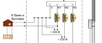
The operating voltage between phases is 380 V, and between phases and zero 220 V. After all, this voltage represents three phases in three different wires, only with different instantaneous potentials and a frequency of 50 Hz.
Electrical wiring in the house should be divided into groups, each lighting line is protected by a single-pole circuit breaker (5). Each group is powered from different phases.
In rooms with high humidity levels, you need to use a difavtomat (6), which is triggered when the current reaches no more than 30 milliamps.
For a kitchen group, it is advisable to install a three-pole circuit breaker (9) and a four-pole circuit breaker (10). This is due to the fact that the kitchen power supply is three-phase, so if a phase is short-circuited to zero, it will be necessary to cut off the zero worker and all phase conductors at the same time.
Three-phase connection
First of all, you need to prepare all the necessary documentation. It includes technical operating conditions that are issued by the organization that supplies electricity. Based on the technical conditions, design documentation for the electrical supply of the facility is drawn up.
You will need the following documents:
- Agreement with the energy supply organization.
- Inspection report of existing electrical equipment.
- Conclusion of a laboratory study of a circuit designed for a specific object.
- The act of delimiting electrical networks by balance sheet.
The project being drawn up takes into account the specifics of further electricity consumption. All consumers are divided into groups, which include sockets and lighting systems. Each group can be switched off separately if repair work is required. At this time, the other group continues to be used without causing unnecessary inconvenience to the owners.
For all groups, calculations of the maximum power consumption of electricity are performed. In accordance with this, the most optimal cross-section of conductors is selected. As a rule, lighting lines are laid with a cable whose cross-section is 1.5 mm2, and for sockets no less than 2.5 mm2 is required. Each group is connected to automatic protective devices that prevent fires in the wiring in the event of a short circuit.
Thus, if you have a connection project, you can calculate the need for materials, instruments and equipment, as well as determine the dimensions of the electrical panel in advance. The attached diagrams mark all the places where switches, sockets, stabilizing devices and other stationary equipment are located.
Direct connection can be made underground or overhead. As a rule, in private homes the second option is used, which has a number of significant advantages. In this case, you can use any connection diagrams with minimal time spent on completing the work. During further operation, overhead lines are much easier to repair. Of great importance is the cost of connection, which is much lower than when using an underground cable line.
When making an air connection, the distance from the house to the pole should be taken into account. which should not exceed 15 m. In the case where the distance is greater than specified, the installation of an additional pole is required. Due to this, severe sagging or breakage of the wire is eliminated under the negative influence of external factors
You should also pay attention to ensure that the wires do not interfere with pedestrians and vehicles. The mounting height of a three-phase line is at least 2.7 m or more
The wires themselves are installed on special insulators, and only then they are brought from the pole to the power panel.
It is recommended to install the power shield on the facade of the building, then the wires go from it to all rooms. If there are electrified extensions, the supply line is also supplied to them from the panel. To connect and account for consumed electricity, a three-phase meter is required. Mostly direct switching devices are used, the operating principle of which resembles a single-phase meter. In this case, you just need to correctly follow the device connection diagram located on its back cover or in the technical data sheet.
In some cases, a semi-indirect connection scheme for a three-phase meter can be used in a private house. The connection diagram is supplemented with a voltage transformer. To pay for consumed electricity, the device readings must be multiplied by the transformation ratio indicated on the transformer.
Possible connection diagrams for a three-phase socket
Safe mounting option for five-pin connectors
In practice, two options for using protection are used:
- only by circuit breaker;
- automatic and RCD.
Let us explain their connection with illustrations.
Socket protection circuit with circuit breaker
All phase and working zero wires from the electric meter to the outlet pass through the circuit breaker. In some cases, the neutral may be allowed to pass without its power contact.
The PE protective conductor is mounted in a continuous manner with a single piece of wire from its busbar in the apartment panel directly to the grounding contact at the socket.
Socket protection circuit by circuit breaker with RCD
In this situation, the machine is mounted in the same way as in the previous case, and the RCD is inserted sequentially after it. To simplify work and save space in the apartment panel, you can use the connection of a differential switch that combines both types of these protections in its housing.
A safe option for installing a 4-pin socket in a five-wire circuit
A slight simplification is made here related to the connection of the protective neutral wire. Since there is no room for it on the plug and socket, the PE conductor is directly laid and connected to the body of the three-phase electrical consumer.
The method is quite suitable for permanently installed electric stoves or machines with asynchronous motors. When the need arises to move an electrical device, for example, three-phase welding, to a more convenient place, then to ensure its safe use, the issue of reconnecting the protective zero will have to be resolved.
After assembling the electrical circuit with a three-phase socket and plug, they must be checked by measuring resistance and voltage.
It is important to do this before connecting to the network
Some useful tips for assembling a shield
When assembling an electrical panel, it is necessary to use only high-quality and reliable electrical products
You should not pay attention to cheaper Chinese analogues; personal safety is much more important
To connect wires to machines, it is best to use special lugs for crimping. Of course, then you will have to purchase pliers with which crimping is performed, but their cost is not too high.
The use of insulating tape is no longer relevant; many electricians use exclusively heat-shrinkable tubing. This consumable is convenient and reliable, and it is not necessary to purchase a hair dryer; you can use an ordinary lighter.
For ease of use, all elements of the electrical cabinet must be marked. Only then will it be possible to quickly and easily turn off the voltage in a certain room. You can make notes on the body of the device or make small signs and attach them to the product with tape.
Branch design features
Most often, a three-phase connection to a house on a power line is carried out by an overhead line, on which a short circuit or break may occur. To prevent them, you should pay attention to:
- the overall mechanical strength of the created structure
- quality of outer layer insulation
- current-carrying material
Modern self-supporting aluminum cables are lightweight and have good conductive properties. They are well suited for installing an air branch. With three-phase power supply to consumers, a SIP core cross-section of 16 mm2 will be sufficient for long-term production of 42 kW, and 25 mm2 - 53 kW.
When a branch is made using an underground cable, pay attention to:
- the configuration of the route being laid, its inaccessibility to damage by unauthorized people and machinery when working in the ground
- protection of ends coming out of the ground with metal pipes to a height no less than average human height
The best option is to completely place the cable in the pipe up to the entry into the control unit and the distribution cabinet.
For underground installation, use only a single piece of cable with strong armor tape or protect it with pipes or metal boxes. In this case, copper conductors are preferable to aluminum ones.
The technical aspects of three-phase connection of a private house in most cases require greater costs and effort than with a single-phase circuit.