The USB interface began to be widely used about 20 years ago, to be precise, since the spring of 1997. It was then that the universal serial bus was implemented in hardware in many personal computer motherboards. Currently, this type of connecting peripherals to a PC is a standard, versions have been released that have significantly increased the data exchange speed, and new types of connectors have appeared. Let's try to understand the specifications, pinouts and other features of USB.
What are the advantages of Universal Serial Bus?
The introduction of this connection method made it possible:
- Quickly connect various peripheral devices to your PC, from the keyboard to external disk drives.
- Make full use of Plug&Play technology, which simplifies the connection and configuration of peripherals.
- Refusal of a number of outdated interfaces, which had a positive impact on the functionality of computing systems.
- The bus allows not only to transfer data, but also to supply power to connected devices, with a load current limit of 0.5 and 0.9 A for the old and new generations. This made it possible to use USB to charge phones, as well as connect various gadgets (mini fans, lights, etc.).
- It has become possible to manufacture mobile controllers, for example, a USB RJ-45 network card, electronic keys for entering and exiting the system
Conclusions and useful video on the topic
The video below explains the main points of pinout of connectors of the 2.0 series and others, and visually explains individual details of the production of soldering procedures.
Having complete information on the pinout of Universal Serial Bus connectors, you can always cope with a technical problem associated with conductor defects. This information will also come in handy if you need to connect some digital devices in a non-standard way.
Would you like to supplement the above material with useful comments or valuable tips on do-it-yourself desoldering? Write comments in the block below, add, if necessary, unique photographic materials.
Maybe you still have questions after reading the article? Ask them here - our experts and competent site visitors will try to clarify unclear points.
Types of USB connectors - main differences and features
There are three specifications (versions) of this type of connection that are partially compatible with each other:
- The very first version that has become widespread is v 1. It is an improved modification of the previous version (1.0), which practically did not leave the prototype phase due to serious errors in the data transfer protocol. This specification has the following characteristics:
- Dual-mode data transfer at high and low speed (12.0 and 1.50 Mbps, respectively).
- Possibility of connecting more than a hundred different devices (including hubs).
- The maximum cord length is 3.0 and 5.0 m for high and low transfer speeds, respectively.
- The rated bus voltage is 5.0 V, the permissible load current of the connected equipment is 0.5 A.
Today this standard is practically not used due to its low throughput.
- The dominant second specification today... This standard is fully compatible with the previous modification. A distinctive feature is the presence of a high-speed data exchange protocol (up to 480.0 Mbit per second).
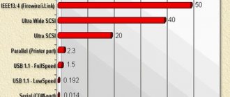
A clear demonstration of the advantages of USB 2.0 over other interfaces (transfer speed 60 MB per second, which corresponds to 480 Mbit per second).
Thanks to full hardware compatibility with the younger version, peripheral devices of this standard can be connected to the previous modification. True, the throughput will decrease up to 35-40 times, and in some cases more.
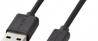
Since these versions are fully compatible, their cables and connectors are identical.
Please note that, despite the bandwidth specified in the specification, the actual data exchange speed in the second generation is somewhat lower (about 30-35 MB per second). This is due to the implementation of the protocol, which leads to delays between data packets. Since modern drives have a read speed four times higher than the throughput of the second modification, that is, it does not meet current requirements.
- The 3rd generation universal bus was developed specifically to solve problems of insufficient bandwidth. According to the specification, this modification is capable of exchanging information at a speed of 5.0 Gbit per second, which is almost three times the reading speed of modern drives. Plugs and sockets of the latest modification are usually marked blue to facilitate identification of belonging to this specification.
USB 3.0 connectors have a characteristic blue color.
Another feature of the third generation is an increase in the rated current to 0.9 A, which allows you to power a number of devices and eliminate the need for separate power supplies for them.
As for compatibility with the previous version, it is partially implemented; this will be discussed in detail below.
Features of cable wiring on connector contacts
There are no special technological nuances associated with soldering cable conductors on the contact pads of connectors.
The main thing in this process is to ensure that the color of the pre-insulated cable conductors matches the specific contact (pin). Also, if you are wiring modifications of outdated versions, you should take into account the configuration of the connectors, the so-called “male” and “female”. The conductor soldered on the male contact must match the soldering on the female contact. Take, for example, the option of wiring the cable to USB 2.0 pins. The four working conductors used in this embodiment are usually marked in four different colors:
- red;
- white;
- green;
- black.
Accordingly, each conductor is soldered onto a pad marked with a connector specification of a similar color. This approach greatly simplifies the work of the electronics engineer and eliminates possible errors during the desoldering process.
A similar soldering technology is applied to connectors of other series. The only difference in such cases is the larger number of conductors that have to be soldered. To simplify your work, it is convenient to use special tools - a reliable soldering iron for soldering wires at home and a stripper for removing insulation from the ends of the wires.
Regardless of the connector configuration, screen conductor soldering is always used. This conductor is soldered to the corresponding contact on the connector; Shield is a protective screen. There are frequent cases of ignoring the protective screen, when “experts” do not see the point in this conductor. However, the lack of a screen dramatically reduces the performance of the USB cable. Therefore, it is not surprising when, with a significant length of cable without a screen, the user experiences problems in the form of interference.
Classification and pinout
Connectors are usually classified by type, there are only two of them:
- A is a plug connected to the female socket installed on the PC system board or USB hub. Using this type of connection, you can connect a USB flash drive, keyboard, mouse, etc. These connections are fully compatible between the initial version and the second generation. With the latest modification, compatibility is partial, that is, devices and cables from earlier versions can be connected to third-generation sockets, but not vice versa.
Type A connectors - B – plug for connecting to a socket installed on a peripheral device, for example, a printer. The dimensions of the classic type B do not allow it to be used for connecting small-sized devices (for example, tablets, mobile phones, digital cameras, etc.). To correct the situation, two standard reduced modifications of type B were adopted: mini and micro USB.
Note that such convectors are compatible only between earlier modifications.
Various Type B Connector Models
In addition, there are extension cables for the ports of this interface. At one end there is a type A plug, and at the other there is a socket for it, that is, in fact, a “female” - “male” connection. Such cords can be very useful, for example, to connect a flash drive without crawling under the table to the system unit.
USB Extension Cable
Now let's look at how contacts are wired for each of the types listed above.
How to choose?
When choosing a cable, you need to decide on the length. The assortment of computer stores has wires of various lengths that allow you to connect devices at the required distance. The optimal wire length is 2-3 meters. There are cords up to 5 meters
It is important to choose the appropriate length so as not to use adapters and extensions in the future. When installing them, the quality of signal transmission is lost, and the operation of the printer may be disrupted
It is also worth paying attention to the data transfer speed. This option is selected based on the characteristics of the printer model. The quality of the wire depends on its width
The wide cable has a high data transfer rate. The HP printer uses a high speed cable. When choosing a USB cable, you need to pay attention to the connection standard. A cable with the USB 2.0 AB standard will be the optimal solution. There is a higher standard of 3.0. The difference between the interfaces is the data exchange speed - 370 Mbit and 5 GB
The quality of the wire depends on its width. The wide cable has a high data transfer rate. HP printer uses high speed cable
When choosing a USB cable, you need to pay attention to the connection standard. A cable with USB 2.0 AB standard will be the optimal solution
There is a higher standard of 3.0. The difference between the interfaces is the data exchange speed - 370 Mbit and 5 GB.
The optimal length of a USB cable is 1.8 m. There are wires 3 meters long. But it is worth remembering that the shorter the cord, the better the transmission of information. The presence of ferrite rings on the cable is an important factor when choosing. The rings are able to reduce noise flows and also suppress electromagnetic interference. A large number of ferrite rings on the cable is characterized by clear and fast transmission of information. Another aspect when choosing a cable for an HP printer is shielding. Thick, durable wires have high signal quality and a long service life.
There are criteria for choosing a power cord. The power cord may have several conductors. The thickness of each of them should be 0.5 millimeters. The higher the value, the better the quality of the cable. When purchasing, you need to check that bending does not leave marks on the insulation. If the cable is deformed or small cracks appear, then you should not purchase the product. The material of the network wires is copper. This wire is safe and can last for many years.
The choice of wire is based on the purpose and model of the HP printer. There are different wires for different purposes. They have their own characteristics and features. Choosing a wire for a printer requires special responsibility. The cable must comply with technical requirements. The device and cable must be compatible. A poor choice can lead to failures and equipment malfunction.
How to install and connect the printer using a cable, see the following video.
USB 2.0 connector pinout (types A and B)
Since the physical plugs and sockets of early versions 1.1 and 2.0 do not differ from each other, we will present the wiring of the latter.
Figure 6. Wiring the plug and socket of type A connector
Designation:
- A – nest.
- B – plug.
- 1 – power supply +5.0 V.
- 2 and 3 signal wires.
- 4 – mass.
In the figure, the coloring of the contacts is shown according to the colors of the wire, and corresponds to the accepted specification.
Now let's look at the wiring of the classic socket B.
Wiring of plug and socket type B
Designation:
- A – plug connected to the socket on peripheral devices.
- B – socket on a peripheral device.
- 1 – power contact (+5 V).
- 2 and 3 – signal contacts.
- 4 – ground wire contact.
The colors of the contacts correspond to the accepted colors of the wires in the cord.
HDMI cable pinout by color
The HDMI cable is divided into 5 groups of 3 cores. And 4 more wires go separately. The connector provides switching of four groups of shielded symmetrical circuits for transmitting digital video signals (aluminum foil shield), separate wires for service data and power.
| Contact number | Purpose | Wire color | Note |
| 1 | Video signal 2+ | White | Red group |
| 2 | Video signal 2 screen | Screen | |
| 3 | Video signal 2- | Red | |
| 4 | Video signal 1+ | White | Green group |
| 5 | Video signal 1 screen | Screen | |
| 6 | Video signal 1- | Green | |
| 7 | Video signal 0+ | White | Blue group |
| 8 | Video signal 0 screen | Screen | |
| 9 | Video signal 0- | Blue | |
| 10 | Tact + | White | |
| 11 | Tact screen | Screen | |
| 12 | Tact - | Brown | |
| 13 | CEC Signal | White | |
| 14 | Utility | White | Yellow group |
| 15 | Asymmetric bus signal SCL | Orange | |
| 16 | Asymmetric bus SDA signal | Yellow | |
| 17 | Earth | Screen | Yellow group |
| 18 | Power supply +5 V | Red | |
| 19 | Connection detector | Yellow | Yellow group |
There is no single color marking for cores and each cable manufacturer may have its own marking. This is exactly what was used in the test HDMI cable.
USB 3.0 pinout (types A and B)
In the third generation, peripheral devices are connected via 10 (9 if there is no shielding braid) wires; accordingly, the number of contacts is also increased. But they are located in such a way that it is possible to connect devices of earlier generations. That is, the +5.0 V contacts, GND, D+ and D-, are located in the same way as in the previous version. The wiring for Type A socket is shown in the figure below.
Figure 8. Pinout of Type A connector in USB 3.0
Designation:
- A – plug.
- B – nest.
- 1, 2, 3, 4 – connectors fully correspond to the pinout of the plug for version 2.0 (see B in Fig. 6), the colors of the wires also match.
- 5 (SS_TX-) and 6 (SS_TX+) connectors for data transmission wires via the SUPER_SPEED protocol.
- 7 – ground (GND) for signal wires.
- 8 (SS_RX-) and 9 (SS_RX+) connectors for data receiving wires using the SUPER_SPEED protocol.
The colors in the figure correspond to those generally accepted for this standard.
As mentioned above, a plug from an earlier model can be inserted into the socket of this port; accordingly, the throughput will decrease. As for the plug of the third generation of the universal bus, it is impossible to insert it into the sockets of the early release.
Now let's look at the pinout for the type B socket. Unlike the previous type, such a socket is incompatible with any plug of earlier versions.
Wiring USB 3.0 type B
Designations:
A and B are plug and socket, respectively.
Digital signatures for contacts correspond to the description in Figure 8.
The color is as close as possible to the color markings of the wires in the cord.
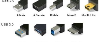
Connector types
The second and third versions of connectors are distinguished by size: Mini USB (small sizes), Micro USB (even smaller sizes); and also by types: A, B.
USB 2.0 type A connector.
A reliable connector whose main characteristic is the ability to withstand more than one connection without losing its integrity.
The cross-section of the connector has a rectangular shape, which creates additional protection when connecting.
Its disadvantage is its large size, and all modern devices are portable, which influenced the development and production of connectors of a similar type, but of a smaller size.
USB 2.0 Type A was introduced in the nineties and is currently still the most used.
A significant number of low-power devices have it: keyboard, mouse, flash drive and others.
USB connector version 2.0 type B.
We mainly find its application in stationary devices of large dimensions. These include scanners, printers, and less commonly ADSL modems.
It is rare, but it still happens that cables of this type are sold separately from the equipment itself, because they are not part of the technical device kit. Therefore, check the complete set of devices.
Connectors of this type are not as popular as type A connectors.
The square and trapezoidal shape is inherent in all type B connectors.
These include both Mini and Micro.
The peculiarity of the cross-section of type “B” connectors is their square shape, which distinguishes it from other types.
Mini USB connectors of the second version, type B.
The name of this type of connector indicates that it has very small dimensions. And this is not surprising, because the modern market increasingly offers miniature goods.
Thanks to the use of personal hard drives, card readers, players and other small devices, USB Mini connectors related to type B have become very popular.
It should be noted that such connectors are unreliable. It becomes loose with frequent use.
But the use of USB Mini Type A connector models is extremely limited.
Micro USB 2.0 type B connectors.
Micro USB connector models are more advanced than Mini USB models.
This type of connector is incredibly small in size.
Unlike the previous mini types presented, these connectors are very reliable with their fastenings and connection fixation.
The Micro USB 2.0 connector type “B” has been recognized in its qualities as uniform for universal use for charging all portable devices.
What will happen over time, when all manufacturers begin to produce equipment adapted specifically to such connectors. It probably won't take long to see it.
But this decision was already made in 2011 by all modern manufacturers, although the Micro USB 2.0 type “B” connector is not yet present on all devices.
USB third version type A connectors.
USB 3.0 connectors have greater speed for information transfer due to additional contacts.
With such changes, feedback compatibility is still maintained. Its use has been established in computers and laptops of the latest generation.
USB connectors third version type B.
The third version of USB type “B” connectors are not suitable for connecting USB connectors of the second version.
It is used in the operation of peripheral devices with medium and large productivity.
Micro USB 3.0.
Modern high-speed external drives, as well as SSD-type drives, are basically all equipped with a connector that is characterized by a high speed of information exchange.
It is increasingly occupying a leading position due to the fact that it has very high-quality connections.
The connector is easy to use due to its compact size. Its predecessor is considered to be a Micro USB connector.
USB connector pinout .
Micro USB connector pinout
To begin with, we present the wiring for this specification.
Micro USB v 2.0 connector wiring
As can be seen from the figure, this is a 5 pin connection; both the plug (A) and socket (B) have four contacts. Their purpose and digital and color designation correspond to the accepted standard, which was given above.
Description of the micro USB connector for version 3.0.
For this connection, a characteristically shaped 10 pin connector is used. In fact, it consists of two parts of 5 pin each, and one of them fully corresponds to the previous version of the interface. This implementation is somewhat confusing, especially considering the incompatibility of these types. Probably, the developers planned to make it possible to work with connectors of earlier modifications, but subsequently abandoned this idea or have not yet implemented it.
MicroUSB connector layout for version 3.0
The figure shows the pinout of the plug (A) and the appearance of the micro USB socket (B).
Contacts 1 to 5 fully correspond to the second generation micro connector, the purpose of the other contacts is as follows:
- 6 and 7 – data transmission via high-speed protocol (SS_TX- and SS_TX+, respectively).
- 8 – mass for high-speed information channels.
- 9 and 10 – data reception via high-speed protocol (SS_RX- and SS_RX+, respectively).
Functions of the “legs” of the micro-USB connector
The micro-USB connector is used to charge small and portable volatile devices and synchronize data between PCs and gadgets. It consists of five "legs". Two “legs” are separated on opposite sides of the case: one is the positive 5V rating, the second is the negative one. This arrangement reduces the likelihood of breakdown.
Close to the negative leg there is another contact, which can easily break if connected to the port carelessly. If this “leg” is damaged, the cable fails
The battery icon may indicate connection progress, but may not actually charge. Most often, this damage results in the gadget not responding to the plug being connected.
The two remaining “legs” are used for data exchange and synchronization between devices. With their help, you can upload and download files from the gadget to your PC and back, transfer videos, photos, and audio. The work is carried out synchronously. If only one contact is damaged, the second one stops working. Knowing the color pinout allows you to solder the wires correctly and resume the plug’s operation.
Mini USB pinout
This connection option is used only in early versions of the interface; in the third generation this type is not used.
Mini USB connector pinout
As you can see, the wiring of the plug and socket is almost identical to the micro USB, respectively, the color scheme of the wires and the contact numbers are also the same. Actually, the differences are only in shape and size.
In this article we have presented only standard types of connections; many manufacturers of digital equipment practice introducing their own standards; there you can find connectors for 7 pin, 8 pin, etc. This introduces certain difficulties, especially when the question arises of finding a charger for a mobile phone. It should also be noted that products are in no hurry to tell how the USB pinout is done in such contactors. But, as a rule, this information is easy to find on thematic forums.
Can it be charged?
If peripherals are connected to the device via OTG, then it will have to power it, which can significantly reduce the overall operating time of the device from the built-in battery. In this regard, many people wonder whether it is possible to recharge such a device through an external source. This is possible, but this requires support for a special mode in the device, as well as a separate wiring of the USB connector for charging.
In fact, the charging mode is most often provided by modern gadget developers, but not everyone allows such a procedure. It should be noted that to switch to this charging mode, a separate USB connector wiring diagram must be used, in which the contacts are closed through a separate resistor.
Pinout of micro usb charging connector
- The USB bus connector appeared around the beginning of 1990, and its main purpose was to be used in household radio equipment. Today, the micro USB connector has become extremely popular not only in household devices, but also in professional multimedia devices. However, its “everyday” origins are clearly visible in the fact that these plug-in format connectors are installed on almost any audio-video equipment, without exception.
The first connecting connectors differed from modern ones in their large sizes, although its socket was normally installed in small-sized portable devices. Over time, the sizes of USB connectors have acquired compact forms in various variants, such as MINI-USB, MICRO-USB and simply USB. These types of connecting devices made it possible to carry out its main functional purpose. At the same time, they differed significantly in size and ease of use from the earlier created analogue.
Device and pinout of micro usb charging connector
The micro usb connecting device consists of five contact pads, an insulated mounting wire is connected to each pad. For precise orientation of the connector when connecting to the mating part of the connector, a special chamfer is made on the edge of its upper shielding part. The contact pads of the connector are numbered from one to five, which are read from right to left. For clarity, this is shown in the picture below. The wiring diagram for the micro USB connector, as well as the purpose of its contacts isolated from each other, are shown in the table:
Micro USB pinout by wire color
The shielding shell also serves as a wire, but is not soldered to a separate contact pad.
Modern connecting devices such as micro USB connectors have fairly good performance characteristics and a relatively low price. Therefore, given the availability of a huge number of different connecting wires of this type in the trade, repairs of such auxiliary equipment are carried out extremely rarely. But still, if you have to replace a defective connector socket, then pinout the micro USB connector will not cause much trouble. Structurally well-made micro USB connectors, even despite their miniature dimensions, they will not allow you to make serious mistakes in installation.