Basic definitions
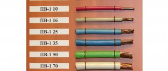
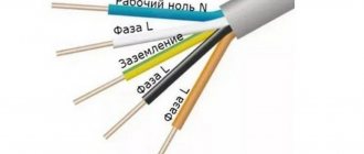
In AC electrical networks up to a thousand volts, the color marking of wires and cables is strictly regulated by state regulations, such as the “Rules for Electrical Installations” (PUE), and this is what the section of the seventh edition in Chapter 1, paragraphs 1.1.29 - 1.1.30 is responsible for. It states that “Identification of wire cores by colors or digital designations” must be used in accordance with GOST P 50462-92 (IEC 446-89). The marking has the following basic designations:
- PE – protective neutral conductor (ground) – bright yellow with a green stripe, or alternating green and yellow stripes;
Important! It is recommended not to use or produce wires of green and yellow shades to avoid resemblance to the grounding conductor.
In 3-phase AC distribution boards, the busbars are painted:
- yellow – L1 (phase A);
- green – L2 (B);
- red – L3 (C);
- blue – block of neutral working conductor N;
- alternating longitudinal or transverse stripes of the same width of yellow-green color - PEN grounding bus.
Important! If the electrical panel housing also serves as a grounding contact, then the location where the wires are connected is indicated by a sign (ground) and is colored yellow-green.
The PUE allows you to designate the color of the main wires, phase and zero, not along the entire length of the bus, but only at the points of connection to the contacts; if the bus is invisible, you are allowed not to color it.
Important! When installing electrical equipment located in the same building, it is necessary to use color marking of wires and cables using the same color schemes.
We must not forget that the designation of wires by color should in no case reduce the degree of electrical safety and convenience when repairing or servicing electrical equipment.
Methods for determining phase and neutral wires
Knowing that in electrical engineering, a phase is a wire through which electricity flows to a device, the user may be interested in whether it is possible to find the phase and zero without using devices. There is a way to do this, although it is not particularly reliable, since network installers do not always comply with the standards for color marking of different types of wires. According to standards, the insulation of the neutral cable should be blue or dark blue, and the ground cable should be painted with yellow and green stripes. For phase wires, the color is not regulated; it can be different, but only different from other cables.
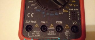
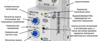
You can find the phase by voltage, which is measured with a multimeter. In the settings, indicate an alternating voltage of more than 220 V. Make contact between two probes with the V and COM sockets. The probe located in V touches the wires - when you touch zero, the device will not show anything, but in phase it will detect a voltage of 7-15 V.
You can also use an automatic machine and an indicator screwdriver. 1-2 cm of insulation is removed from the wires. Turn on the machine and bring the screwdriver with the working side to the wire, while keeping your finger on the metal piece next to the handle. When brought to the phase, the light comes on.
Neutral conductor
The neutral conductor or, as it is also called, neutral performs a simple but important function. It equalizes the loads in the network, providing a voltage of 220 Volts at the output. Eliminates phase jumps and distortions, neutralizing them. Not surprisingly, its symbol is the letter n - derived from the English word Neutral. And the combination of designations n, l in electrics always go side by side.
In the distribution panel, all cables of a given color are grouped on one, zero bus with the corresponding letter abbreviation. The sockets also have the necessary markings.
Therefore, the master will never confuse where to attach the special zero contact.
This marking and operating principle are applicable to both single-phase and three-phase networks.
Electric current and electric charge
Electric charge is a physical scalar quantity that determines the ability of bodies to be a source of electromagnetic fields. The carrier of the smallest or elementary electric charge is the electron. Its charge is approximately -1.6 to 10 to the minus nineteenth power of Coulomb.
Electron charge is the minimum electrical charge (quantum, portion of charge) that occurs in nature in free, long-lived particles.
Charges are conventionally divided into positive and negative. For example, if we rub an ebonite stick on wool, it will acquire a negative electrical charge (excess electrons that were captured by the atoms of the stick upon contact with the wool).
Static electricity on the hair has the same nature, only in this case the charge is positive (the hair loses electrons).
By the way, you can read more about what current, voltage and resistance are in our separate article on Ohm’s law.
Electric current is the directed movement of charged particles (charge carriers) along a conductor. The very movement of charged particles occurs under the influence of an electromagnetic field - one of the fundamental physical fields.
Electric current can be direct or alternating . With constant current, the direction and magnitude of the current do not change. Alternating current is a current that changes over time.
The DC source is, for example, a battery. But it is alternating current that is used in household sockets that are in our homes. The reason is that alternating currents are much easier to receive and transmit over long distances.
By the way! For our readers there is now a 10% discount on any type of work
The main type of alternating current is sinusoidal current . This is a current that first increases in one direction, reaches a maximum (amplitude), begins to decrease, at some point becomes equal to zero and increases again, but in a different direction.
What is the difference between a phase conductor and a neutral conductor?
The purpose of the phase cable is to supply electrical energy to the desired location. If we talk about a three-phase electrical network, then there are three current-supply wires per single zero wire (neutral). This is due to the fact that the flow of electrons in a circuit of this type has a phase shift of 120 degrees, and the presence of one neutral cable in it is quite sufficient. The potential difference on the phase wire is 220V, while the zero wire, like the ground wire, is not energized. On a pair of phase conductors the voltage value is 380 V.
Line cables are designed to connect the load phase to the generator phase. The purpose of the neutral wire (working zero) is to connect the zeros of the load and the generator. From the generator, the flow of electrons moves to the load along linear conductors, and its reverse movement occurs through neutral cables.
The neutral wire, as mentioned above, is not energized. This conductor performs a protective function.
Thus, damage to the installation will be followed by its rapid disconnection from the general network.
In modern wiring, the sheath of the neutral conductor is blue or light blue. In old circuits, the working neutral wire (neutral) is combined with the protective wire. This cable has a yellow-green coating.
Depending on the purpose of the power transmission line, it may have:
- Solidly grounded neutral cable.
- Insulated neutral wire.
- Effectively grounded neutral.
The first type of lines is increasingly used in the design of modern residential buildings.
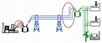
In order for such a network to function correctly, the energy for it is generated by three-phase generators and is also delivered through three phase conductors under high voltage. The working zero, which is the fourth wire, is supplied from the same generator set.
Visually about the difference between phase and zero in the video:
Phase is plus or minus
In the process of carrying out apartment renovations or repairing home electrical equipment, many, usually unexperienced amateur electricians, have questions about what color of wire
needs to be connected to a particular cable core,
where is the phase and where is the zero
in the socket, and others. All these questions are very correct and necessary, because not only the safety of the electrician and the people around him, but also the uninterrupted operation of the electrical network in the house or apartment depends on the correct answer to them. Color marking of each core in a modern cable is not a whim or an advertising “trick” of manufacturers. On the contrary, this is a strict standard that is followed all over the world, determined by safety regulations, and also significantly simplifies the installation procedure and speed.
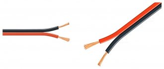
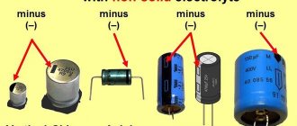
Color of wires plus (+) and minus (-) in DC networks
Is the red wire positive or negative? Such questions arise when working with DC electrical circuits.
Red
To remember which plus is red or black, they use the name of a well-known international organization - the Red Cross. This phrase suggests that red means plus.
Black
Black color indicates the negative conductor. These markings can be seen on typical household equipment:
- power supplies;
- audio, video equipment;
- other devices with electronic software control units.
Plus
The polarity of conductors must be observed when repairing standard electrical equipment of cars. In some situations, confusion with plus and minus is accompanied by a violation of the functional state.
Minus
The high power of connected consumers increases the responsibility for performing repair and adjustment work. In such situations, it is necessary to eliminate errors in determining polarity. Strong direct current is used to supply electricity:
- warehouse and municipal transport;
- lifting mechanisms;
- sensors and automation.