By appearance
If the markings are worn out or unclear, determining the polarity of the capacitor is sometimes possible by analyzing the appearance of the case. In many containers with terminals located on one side and not mounted, the positive leg is longer than the negative leg. Products of the ETO brand, now obsolete, look like 2 cylinders placed on top of each other: a larger diameter and small height, and a smaller diameter, but significantly higher. The contacts are located in the center of the ends of the cylinders. The positive terminal is mounted at the end of a cylinder with a larger diameter.
For some powerful electrolytes, the cathode is located on the body, which is connected by soldering to the chassis of the electrical circuit. Accordingly, the positive terminal is isolated from the housing and located on its upper part.
The polarity of a wide class of foreign, and now domestic, electrolytic capacitors is determined by the light stripe associated with the negative pole of the device. If the polarity of the electrolyte cannot be determined either by the markings or by its appearance, then even then the problem of “how to find out the polarity of a capacitor” is solved by using a universal tester - a multimeter.
Results and practical recommendations
There is little point in buying complex and expensive equipment in order to test capacitors. It is quite possible to use a regular multimeter with a suitable range for this purpose. The most important thing is to use its capabilities wisely and correctly.
Although the multimeter is not a highly specialized device and its capabilities are limited, it is quite enough for diagnostic activities and repair of a huge number of popular radio-electronic devices.
Please add your comments to the block below, post photos and ask questions of any complexity on the proposed topic of the article. Tell us about your experience, how you diagnosed capacitors for efficiency and performance. Share recommendations and useful information that may be useful to site users.
You may also be wondering how to connect the wires to each other.
What happens if you reverse the polarity?
If you make a mistake with the polarity of an electrolytic capacitor, it will definitely fail! The resistance of the capacitor with reverse polarity is small, so a significant current will flow through its circuit. This will cause rapid overheating, boiling of the electrolyte, the vapors of which will rupture the housing. The same effect will be caused by an increase in operating voltage above that indicated on the case. To eliminate bad consequences, the top cover of the case is made profiled, with grooves-recesses on the top cover.
It will be interesting What is the difference between a starting capacitor and a working capacitor?
With increased pressure inside, the lid diverges along these grooves, releasing vapors out. It should be noted that electrolytic capacitors used in computer power supplies and motherboards may fail after several years of normal operating conditions. The fact is that in capacitors, due to the presence of electrolyte, electrochemical processes constantly occur, aggravated by heavy operating conditions and elevated temperatures.
Parallel connection of capacitors
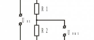
Several capacitors can be connected in series or in parallel. When connected in parallel, the capacitances of all capacitors are summed. With a series connection, the total capacitance of the capacitor bank is less than the smallest one, since the reciprocals of the capacitances are added. But the voltage at which such a battery can operate will be greater than the operating voltage of one capacitor.
On motherboards, the low-voltage voltage source circuit that powers the processor core uses several similar capacitors connected in parallel.
An interesting question: why not put one capacitor with a capacity equivalent to the capacitance of a bank of capacitors?
The fact is that for parallel-connected capacitors, the total ESR will be much less than the ESR of one capacitor. Because when resistances are connected in parallel, the total resistance decreases.
What other parameters characterize capacitors?
Generally speaking, there are many such parameters. We are not having a Nobel lecture here, so we will limit ourselves to only the necessary minimum, which will be useful in practical activities. Rated operating voltage. The capacitor can be used in modes when the voltage across it does not exceed the operating voltage.
For example, you can use an electrolytic capacitor with an operating voltage of 10 V in +5 V or +3 V circuits.
The higher the operating voltage of an electrolytic capacitor with equal capacity, the larger its dimensions.
The operating voltage on ceramic and other capacitors may not be explicitly stated or not stated at all - especially if the capacitor is small.
Complete information about all parameters of the capacitor is available in the corresponding datasheet (reference data), which is available on the website of the manufacturer.
ESR (Equivalent Series Resistance) - equivalent series resistance. The capacitor terminals and their contacts with the plates have non-zero, although very small, resistance. This resistance is active, therefore, in accordance with Ohm's and Joule-Lenz's laws, when current flows through this resistance, heat will be dissipated.
This will cause the capacitor to heat up.
Therefore, electrolytic capacitors usually indicate the maximum operating temperature.
Computer power supplies and motherboards use special capacitors with reduced ESR.
The ESR value for such capacitors can range from hundredths to tenths of an Ohm.
The ESR value can be determined by special markings (most often 2 Latin letters) on the capacitor body. The correspondence of these letters to real ESR values is indicated in the datasheet.
Features of testing different types of capacitors
There are many types of radio components that differ in the material of the dielectric, plates, and type of electrolyte, so they have different methods for diagnosing the operating condition.
To check the suitability of a ceramic capacitor, set the highest measurement limit of the ohmmeter. A sign of serviceability will be a measured resistance of at least 2 MOhm. For other values, the part is changed.
To test a tantalum capacitor, select the largest measurement limit in ohms. If the resistance is 0, change it. Before testing a high-capacity, high-voltage electrolytic capacitor, maximum discharge is necessary. Residual voltage will damage the device.
SMD capacitors are non-polar, so they are tested like ceramic ones, determining suitability using an ohmmeter.
For a film capacitor with a short circuit, the reading will be 0. If there is an internal break, the analog multimeter will show infinity, the digital multimeter will show 1.
Testing without soldering
It is impossible to examine a radio component without desoldering; the reading will be incorrect due to the influence of other elements of the circuit. The proximity of transformers, inductance, and fuses introduces an error into the measurement. Connecting them in parallel or in series will increase or decrease the test result. To correctly assess the condition, the capacitor is desoldered.
Without soldering, you can approximately determine the operation of a section of the circuit. To do this, touch the legs of the part with probes and measure the resistance. If the reading increases and then decreases, the part is working properly.
It must be remembered that capacitor monitoring is only possible up to a maximum value of 200 µF. Electrical measuring instruments do not measure large parameters. If the value is less than 0.25 µF, the capacitors are checked only for short circuits.
LED polarity: how to determine plus and minus
When using LEDs in creating various circuits, they must be installed correctly. Soldering in most cases does not create problems; determining the polarity is a little more difficult if you do not have experience working with testing equipment.
How to determine polarity with a multimeter tester
The easiest way to check the LED is with a multimeter. When connecting the pins in the “dialing” mode to the electrodes, you can get 2 results: the LED lights up and displays a number on the screen depending on the color of the radiation, or shows a very large number. With the first option, we can conclude that the light source is working and connected to the multimeter correctly (plus to plus, minus to minus).
The second method of using a multimeter is to switch to resistance testing. If the red probe touches the plus, the black probe touches the minus, a value in the range of 1600–1800 appears on the screen.
If the multimeter has a PNP compartment, the E (emitter - “+”) and C (collector – “-”) compartments are required to determine the polarity of the LED. The light source glows if the cathode is inserted into “C” and the anode into “E”.
If an NPN multimeter compartment is used, the LED will light if the legs are swapped.
By appearance
In the production of LEDs, different housings are used. DIP elements with a cylindrical body of various diameters are widely used. There are many surface mount SMDs being manufactured. Ultra-bright light sources differ in the size of their housings and crystals. An experienced radio amateur determines the cathode and anode by external signs.
- longer anode leg;
- the silhouette in the flask is smaller at the anode, the shape of the cathode resembles a flag;
- a source with a power of more than 1 W has a “+” marking on the anode leg.
- the cathode is indicated by a cut on the body;
- the heat sink on the back of the case is located closer to the anode;
- The “P” pictogram is facing the anode with the top shelf, the top of the “T” pictogram is facing the cathode.
Some manufacturers put certain symbols on SMD LED housings that allow you to determine the polarity.
Important! There are SMDs made according to a different principle (some manufacturers do not comply with the standards). On complex models there are always symbols “+” and “−”
Any non-semiconductor radio tube (zener diode) consists of an anode, cathode and grid. The cathode is always a heated electrode made in the shape of a cylinder. During thermionic emission, electrons move to the anode (box or plate) - a tungsten conductor with high resistance.
To determine the performance of the zener diode, use a multimeter in ringing mode. If a positive probe is applied to the anode, a negative probe to the cathode, the zener diode will open and the voltage value will be visible on the screen. If you swap the probes, the zener diode will close and the number 1 will appear on the screen.
By supplying power
To use power connection testing, a 3-6V source and any wattage resistor of 300-470 ohms are required. The resistor is soldered to one leg of the multimeter. Then you need to touch the leads with the probes. The LED lights up if the positive probe touches the anode, and the negative probe touches the cathode.
Technical documentation
A large amount of information (dimensions, pinout, electrical parameters) about the semiconductor light source is provided by manufacturers in the technical documentation. It is issued when purchasing large quantities of electronic components along with other accompanying documentation. If you buy one or more LEDs, the seller will not provide technical documentation.
If the brand of the product is known, the data can be found in reference books and on the Internet.
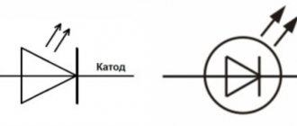
In the diagram, a semiconductor light source is indicated by a pictogram in the shape of a triangle, at the top of which a line is drawn perpendicular to the base. The top is directed towards the cathode. The LED is indicated by 2 arrows above the image.
How to determine where is the anode and where is the cathode?
When determining the cathode and anode, you must first focus on the direction of the current, and not on the polarity of the power source. Despite the fact that these concepts are closely related to the polarity of the current, they are more determined by the directions of the electricity vectors.
For example, in batteries, when recharging, the roles of the cathode and anode change. This is due to the fact that during charging the direction of the electric current changes. The electrode that acts as an electrode when the battery is operating in power source mode during charging performs the functions of a cathode and vice versa - the cathode turns into an anode.
In Fig. 1, the electrolysis process is depicted, during which the movement of anions (negative ions) and cations (positive ions) occurs. Anions rush towards the anode, and positive cations move towards the cathode.
Rice. 1. Electrolysis
During electrolysis, charge carriers of different signs move, however, by definition, the anode is the electrode into which current flows. In the figure, the anode is connected to the positive pole of the current source, which means that current conditionally flows into this electrode.
Pay attention to Figure 2, which shows a diagram of a galvanic cell. Rice
2
Galvanic cell
2. Galvanic cell
Rice. 2. Galvanic cell
The positive terminal of the current source is the cathode, and not the anode, as one might expect. By carefully studying the operating principle of a galvanic cell, you can understand why the anode is the negative pole.
Pay attention to the diagram of the structure of a galvanic current source. The arrows (above) indicate the direction of movement of electrons, but the direction of current is conventionally considered to be movement from plus to minus
That is, when the circuit is closed, the current enters precisely the negative pole, which is the anode on which the oxidation reaction occurs
In other words, the current from the positive electrode passes through the load to the anode, which is the negative pole of the galvanic cell. With a thoughtful approach, everything falls into place
That is, when the circuit is closed, the current enters precisely the negative pole, which is the anode on which the oxidation reaction occurs. In other words, the current from the positive electrode passes through the load to the anode, which is the negative pole of the galvanic cell. With a thoughtful approach, everything falls into place.
When determining the positions of the anode and cathode in radio-electronic elements, reference materials are used.
The purpose of the electrodes is indicated by:
- body shape (Fig. 3);
- lead length (for LEDs) (Fig. 4);
- marks on the housings of devices or the anode mark;
- different thickness of diode leads.
Rice. 3. Diode
Rice. 4. LED electrodes Determining the pin assignments of semiconductor diodes can be determined using measuring instruments. For example, all types of diodes (except zener diodes) conduct current in only one direction. If you connect a tester or ohmmeter to a diode and it shows insignificant resistance, then the anode is connected to the positive probe of the device, and the cathode is connected to the negative probe.
If the conductivity type of the transistor is known, then using the same tester you can determine the emitter and collector terminals. Between them, the resistance is infinitely high (there is no current), and between the base and each of them there will be conductivity (only in one direction, like a diode). Knowing the type of conductivity, by analogy with a diode, you can determine where the anode is and where the cathode is, and therefore determine the terminals of the collector or emitter (see Fig. 5).
Rice. 5. Transistor on the circuits and its electrodes
As for vacuum diodes, they cannot be checked by measuring with conventional instruments. Therefore, their pins are located in such a way as to eliminate connection errors. In electronic tubes, the terminals exactly match the location of the contacts of the socket intended for this radio element.
Using a multimeter
Before conducting experiments, it is important to assemble the circuit so that the test voltage of the direct current source (DC) does not exceed 70-75% of the nominal value indicated on the drive case or in the reference book. For example, if the electrolyte is designed for 16 V, then the power supply should produce no more than 12 V. If the electrolyte rating is unknown, the experiment should be started with small values in the range of 5-6 V, and then gradually increase the voltage at the power supply output.
The capacitor must be completely discharged - to do this, you need to short-circuit its legs or leads for a few seconds with a metal screwdriver or tweezers. You can connect an incandescent lamp from a flashlight to them until it goes out or a resistor. Then you should carefully inspect the product - there should be no damage or swelling of the body, especially the protective valve.
The following devices and components will be required:
- IP - battery, accumulator, computer power supply or specialized device with adjustable output voltage;
- multimeter;
- resistor;
- installation accessories: soldering iron with solder and rosin, side cutters, tweezers, screwdriver;
- marker for applying polarity marks to the body of the electrolyte being tested.
Then you should assemble the electrical circuit:
- parallel to the resistor, using “crocodiles” (i.e., probes with clamps), connect a multimeter configured to measure direct current;
- connect the positive terminal of the IP to the terminal of the resistor;
- Connect the other terminal of the resistor to the contact of the capacitor, and connect its 2nd contact to the negative terminal of the IP.
If the polarity of the electrolyte connection is correct, the multimeter will not record the current. Thus, the contact connected to the resistor will be positive. Otherwise, the multimeter will show the presence of current. In this case, the positive contact of the electrolyte was connected to the negative terminal of the IP.
According to method 3, a device measuring DC voltage is connected in parallel not to the resistance, but to the capacitance being tested. If the poles of the capacitance are correctly connected, the voltage on it will reach the value set on the IP. If the minus of the IP is connected to the plus of the capacitance, i.e. incorrectly, the voltage on the capacitor will rise to a value equal to half the value output by the IP. For example, if there is 12 V at the power supply terminals, then there will be 6 V at the capacitance.
After completing the checks, the container should be discharged in the same way as at the beginning of the experiment.
An electrolytic capacitor is a strange electronic component that combines the properties of a passive element and a semiconductor device. Unlike an ordinary capacitor, it is a polar element.
Instructions
1.
For domestically produced electrolytic capacitors, the ends of which are located radially or axially, to determine the polarity, find the plus sign located on the housing. The outcome closest to which it is placed is positive. Some old Czech-made capacitors are marked in a similar way.
2.
Capacitors of coaxial design, in which the housing is designed to be connected to the chassis; usually prepared for use in anode voltage filters of devices made on lamps. Because it is correct, in most cases the negative plate is placed on the body, and the positive plate is placed on the central contact. But there may be exceptions to this rule, therefore, if in doubt, look for markings on the device body (plus or minus designation) or, if there is none, check the polarity using the method described below.
3.
A non-standard case appears when checking electrolytic capacitors of type K50-16. Such a device has a plastic bottom, and the polarity marking is placed directly on it. Occasionally, the minus and plus signs are arranged in such a way that the totals pass directly through their centers.
4.
An outdated type capacitor could be mistaken for a diode by the uninitiated. Typically, the polarity on its body is indicated by the method described in step 1. If there is no marking, know that the result, located on the side of the body thickening, is connected to the correct lining. Do not disassemble such capacitors under any circumstances - they contain toxic substances!
5.
The polarity of modern imported electrolytic capacitors, regardless of their design, can be determined by the strip located next to the negative result. It is applied in a color contrasting to the color of the body, and is intermittent, i.e. seems to consist of minuses.
6.
To determine the polarity of an unmarked capacitor, assemble a circuit consisting of a continuous voltage source of several volts, a one-kilo-ohm resistor and a microammeter, combined in steps. Completely discharge the device, and only then connect it to this circuit. Once fully charged, read the device readings. After this, disconnect the capacitor from the circuit, completely discharge it again, plug it into the circuit, wait until it is fully charged and read the new readings. Compare them with the previous ones. When connected in positive polarity, the loss is noticeably less.
Automotive stores sell lead-acid batteries of direct polarity (all domestic cars are equipped with them) and reverse polarity (installed on some foreign-made cars). Before purchasing a battery, you need to determine its polarity
.
You will need
- Voltmeter
Instructions
1.
The service life of every battery is limited and, as usual, is no more than five years.
Having worked for the allotted time, the time inevitably comes to replace the power unit. And if the task of owners of domestically produced cars is to choose a battery of the appropriate capacity and give preference to a certain brand, then owners of imported cars need to find out the polarity
of the battery before purchasing.
2.
To achieve this task, the battery is removed from the battery socket and positioned in such a way that when visually inspected from above, its terminals must be at the bottom. Please note that one of them is slightly thinner than the other (it is negative).
3.
If the negative terminal is located on the left (bottom) of the battery, then the battery has reverse polarity.
4.
In cases where the thinner terminal on the right is larger, the battery has straight polarity.
5.
To finally make sure that the polarity of the battery is determined correctly, attach a voltmeter to it. In this case, the scarlet probe of the device removes voltage from the thick terminal, and the black probe from the thin one. The reading on the scale without the minus sign confirms the battery parameters being studied.
Video on the topic
Note!
Installing a battery with the wrong polarity into a car is scary because you won't be able to connect cables to its terminals.
Any diode changes its conductivity depending on the polarity of the voltage applied to it. The location of the electrodes on its body is not indicated invariably. If there is no corresponding marking, you can determine which electrode is connected to which output on your own.
Instructions
1.
First of all, determine
the polarity
of the voltage on the probes of the measuring device you are using.
If it is universal, set it to ohmmeter mode. Take any diode on the body of which the location of the electrodes is indicated. In this designation, the “triangle” corresponds to the anode, and the “stripe” corresponds to the cathode. Try connecting the probes to the diode in different polarities. If it conducts current, then the probe with the correct potential is connected to the anode, and with a negative potential - to the cathode. Remember that the polarity
in the resistance measurement mode on pointer instruments may differ from that indicated for the voltage and current measurement modes. But on digital devices it is traditionally identical in all modes, but it still doesn’t hurt to check.
2.
If you are testing a directly heated vacuum diode, first of all, find that it has a combination of pins between which the current passes independently of the polarity of the connection of the measuring device.
This is the filament, which is also the cathode. the diode's
rated filament voltage . Apply a continuous voltage of the appropriate magnitude to the filament. Connect the probe of the device on which the negative potential is located to one of the pins of the filament, and with the positive probe touch the remaining ends of the lamp in turn. Having found a pin that, when touched with a probe, displays a resistance less than infinity, conclude that this is the anode. Directly heated strong vacuum diodes (kenotrons) can have two anodes.
3.
In an
indirectly heated diode Having found it, apply alternating voltage to it, the effective value of which is equal to that indicated in the reference book. After this, among the other results, find two of them, between which current flows at a certain polarity. The one to which the probe with a positive potential is connected is the anode, the opposite one is the cathode. Remember that many indirectly heated vacuum diodes have two anodes, and some have two cathodes.
4.
A semiconductor diode each has two outputs. Accordingly, everyone can connect the device to it using two methods. Find the arrangement of the element in which current passes through it. A probe with a positive potential will be connected to the anode, and a probe with a negative potential will be connected to the cathode.
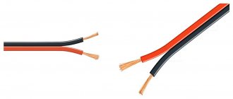
At first glance, indicate the polarity
It makes no sense that alternating voltage is applied to it.
But when there are several dynamic heads in the speaker system, they need to be turned on in phase. It is customary to indicate on the results of the head the polarity
at which the diffuser moves forward.
Instructions
1.
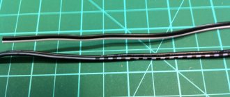
Make a special probe to test the speakers.
To do this, take a regular pocket flashlight based on an incandescent lamp. Remove the switch from it, and instead of the latter, connect two probes. They must strictly have insulated handles, so that at the moment the voltage is turned off, a self-induction voltage appears on the head outputs. Check the polarity
of the voltage on the probes using a test voltmeter. Label them accordingly. Make sure that if the probes are shorted, the lamp lights up.
2.
Unplug the amplifier and each stereo system (including the outlet).
Disconnect both speaker outputs from the rest of the speaker system. Connect the probes to the ends of the head without touching either the ends or the metal parts of the probes. At this moment, keep an observant eye on the diffuser. If it moves outward when connected and inward when disconnected, the polarity
is positive.
If the opposite pattern is observed, change the polarity
of connecting the probes, and then repeat the test.
After this, mark on the frame of the dynamic head with a permanent felt-tip pen the polarity
corresponding to the polarity of connecting the probes.
3.
Carry out a similar operation for the remaining speakers within one speaker system. Regardless of how they are connected (directly or via a crossover), connect them in phase in such a way that the red contact on the rear wall of the speaker corresponds to the positive results of the heads.
4.
Also check and, if necessary, alter the second speaker system. After closing the cabinets of both speakers, check whether they are correctly connected to the amplifier. The cable used to make this connection has special red marks. In all cases, connect the conductor with a mark to the red terminal, and the conductor without a mark to the black one.
5.
Turn on the stereo system. Compare its sound with the one that took place before the alteration.
Video on the topic
It would seem, why indicate the polarity on the speaker of a stereo system? It is supplied with alternating voltage. However, if there are several acoustic heads in the system, they must be turned on in phase. The results of one or the other head indicate the polarity value at which the diffuser moves in the forward direction.
You will need
- – pocket flashlight with incandescent lamp;
- – probes with insulated handles;
- – indelible marker;
- – voltmeter.
Instructions
1.
To determine the polarity of the speaker, make a probe device. Take an ordinary pocket flashlight with an incandescent lamp. Disconnect the switch from it, instead of which you will need to connect two probes. The probes must have insulated handles, since when the voltage is turned off, a self-induction voltage appears at the head ends.
2.
With the support of a test voltmeter, check the polarity on the probes, and then apply the appropriate markings to the probes. When the probes close, the lamp should light.
3.
Turn off the amplifier and the entire speaker system, and unplug the cord from the outlet. After this, disconnect the results of the dynamic head from the rest of the system circuits. Next, connect both probes to the results of the head, avoiding touching the results and the metal parts of the probes themselves. And look at the diffuser carefully. If it moves outward when connected, and inward when disconnected, then the polarity is positive. If the opposite picture is observed, it is necessary to change the polarity of connecting the probes, and then repeat the test.
4.
On the head frame, mark the polarity, preferably with a permanent marker, which corresponds to the polarity of connecting the probes.
5.
Do the same operations for the remaining speakers of the speaker system. And it doesn’t matter whether they are connected through a crossover or directly, it is necessary to connect them in phase so that the positive results of the heads correspond to the red contact on the back wall of the speaker itself.
6.
Check and modify, if necessary, the second speaker system. Check by closing the housings of the 2 speakers whether their connection to the amplifier is positive. You can mark the cable making such a connection with red marks. In any case, the conductor with the mark should be connected to the red terminal, and the one without the mark should be connected to the black terminal.
7.
Turn on the stereo system and compare the sound it makes now with the sound it made before your intervention.
Physicians and psychophysiologists long ago drew attention to the fact that one color or another has an identical effect on all people. For example, scarlet color has a stimulating effect, purple disturbs, blue calms, and green creates a feeling of stability in life.
The most famous expert, the one who studied the effect of colors on people’s state of mind, is Max Luscher. He identified four psychotypes of people, based on their color preferences.
Color Personality Types
Red psychotype
People who prefer red are very energetic, they can be compared to an “indestructible motor”. They, as usual, are constantly excited and love this state. As a result of stress, they often experience nervous exhaustion and irritation.
Yellow psychotype
For people of this type, the most important thing is their personal will and the likelihood of self-realization. They love experiments and are not afraid of changes in life. Because of their autonomy, they often feel unsatisfactorily loved and lost.
Blue Psychotype
For these people, the most important thing in life is a peaceful pace of life; they love peace and tranquility. Because they choose to live a “smooth existence” without surprises or unplanned actions, these people often feel sad and alienated when they are around the people who love them.
Green psychotype
People of this temperament love to control the situation and themselves. They calculate the development of events in advance, know what they want to get and what they are willing to give for it. Spontaneity is not one of their qualities. For these people, it is important how they look in the eyes of others and they will take advantage of every opportunity in order to increase their rank.
Video on the topic
Note!
Completely discharge the capacitor before checking and touching its results. When assembling or repairing the structure, always install the device only in the correct polarity; on the contrary, it may break.
Electrical capacitors are common components of any pulse, electrical or electronic circuit. Their main task is to accumulate charge, which is why they are called passive devices. Electric capacitors consist of two metal electrodes in the form of plates (plates). A dielectric is placed between them, the thickness of which is much less than the dimensions of the plates themselves.
How to test a non-polar capacitor with a multimeter
The operation of radio electronics also involves troubleshooting equipment. Therefore, when considering non-polar capacitors, one cannot abstract from the topic of diagnosing their performance.
As practice shows, in most cases the cause of tank failure is breakdown, which leads to a decrease in leakage resistance. That is, the element practically becomes a conductor. Such a malfunction can often be determined by the appearance of the container (see Figure 5); if this does not help, you will need a simple digital or analog multimeter.
Figure 5. “Burnt” (broken) container
Using the device, you should measure the leakage resistance; in the working elements it should be infinitely large. The check is performed as follows:
- it is necessary to completely dismantle the part, or unsolder one of its terminals, in order to exclude the influence of other circuit elements on the multimeter readings;
- set the device to continuity testing or resistance measurement mode (select the maximum limit);
- we connect the probes to the output contacts (Figure 6), while trying not to touch them, otherwise the device will show skin resistance;
Figure 6. Connecting the container to the measuring device
We carry out a measurement; if the capacitance is in good condition, one will be displayed on the screen (Figure 7), which indicates an infinitely large resistance between the plates.
Figure 7. The device in dialing mode shows an infinitely high resistance
Unfortunately, this method can only test the capacitance for breakdown; this method is not suitable for determining an internal break. In this case, you can distinguish a broken part from a functional one by measuring its capacity; some models of multimeters have this functionality. The principle of testing is practically the same as testing for breakdown, with the exception that the device must be switched to capacitance measurement mode.
Capacitor Capacitance Measurement
Capacitance is the main characteristic of a capacitor. It is indicated on the outer shell of the device, and if you have a tester, you can measure the real value and compare it with the nominal value.
The multimeter switch is switched to the measurement range. The value is set equal to or close to the value indicated on the component. The capacitor itself is installed in special holes –CX+ (if they are on the multimeter) or using probes. The probes are connected in the same way as when measuring in resistance mode.
When connecting the probes, the resistance value should appear on the monitor. If it is close to the nominal characteristic, the capacitor is working. When the discrepancy between the received and nominal values differs by more than 20%, the device is broken and needs to be replaced.
Purpose of the diode
Semiconductor diode elements are present in almost all household electrical appliances. LEDs are used in the production of lighting fixtures and LED TVs.
Semiconductor diodes are classified according to:
- crystal material (silicon, selenium, indium phosphide, germanium);
- sizes (microalloy, spot, flat);
- pn junction production technologies (diffusion, alloy, epitaxial);
- frequency (low-frequency, high-frequency, ultra-high-frequency, impulsive);
- area of use (rectifiers and special ones).
Rectifier diodes are designed to convert alternating voltage to direct voltage. They are installed in the circuit in the form of a diode bridge, which can be used in radio equipment, power supply, charger.
Rectifiers are divided into:
- low current (up to 0.3 ampere);
- average power (0.3-10 amperes);
- power (10-100,000 A, up to 6 kV).
Semiconductor special diode elements:
- varicaps (capacitive diodes);
- thyristors (with an additional output for switching to the open state);
- triacs (current passes in 2 directions);
- Zener diodes (stabilize voltage from 2 volts in a breakdown state, a separate type of stabiistors (normistors) for a voltage of 0.7-2 volts);
- Schottky diodes (for low-voltage circuits paired with a zener diode);
- tunnel diode elements (low negative resistance);
- dinistors (do not contain control electrodes, are mounted in switches);
- magnetic diodes (volt-ampere characteristics change in a magnetic field, mounted in motion sensors, control devices);
- photodiodes (convert light energy into electrical energy);
- LEDs (convert electrical energy into light).
Using a battery
If there is no power source, you can try to determine the location of the leads from the galvanic cell, but you should keep in mind the features of such a test:
- The battery may produce a voltage that is insufficient to open the pn junction.
- household galvanic cells have low power, and the output load current is small - it depends on the initial power of the battery and on the residual charge.
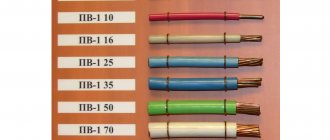
The table shows the parameters of some domestic LEDs. Obviously, common one-and-a-half-volt chemical current sources will not be able to ignite any device on the list.
| Device type | Forward voltage drop, V | Operating current, mA |
| AL102A | 2,8 | 5 |
| AL307A | 2 | 10 |
| AL307V | 2,8 | 20 |
To increase the voltage, you can connect the batteries in series. To increase power - in parallel (only for elements of the same voltage!). The result may be a cumbersome design that does not guarantee the final result. Therefore, it is better to use this method in cases where there are no other ways.
Capacitor positive symbol
On domestic Soviet products, only the positive contact was indicated with a “+” sign. This sign was applied to the case next to the positive terminal. Sometimes in the literature the positive terminal of electrolytic capacitors is called the anode, since they not only passively accumulate charge, but are also used to filter alternating current, i.e. have the properties of an active semiconductor device. In some cases, the “+” sign is also placed on the printed circuit board, close to the positive terminal of the drive located on it.
On products of the K50-16 series, polarity markings are applied to the bottom, made of plastic. For other models of the K50 series, for example K50-6, the “plus” sign is painted on the bottom of the aluminum case, next to the positive terminal. Sometimes imported products produced in the countries of the former socialist camp are also marked on the bottom. Modern domestic products meet global standards.
The marking of SMD (Surface Mounted Device) capacitors intended for surface mounting (SMT - Surface Mount Technology) differs from ordinary ones. Flat models have a black or brown body in the form of a small rectangular plate, part of which at the positive terminal is painted over with a silver stripe with a plus sign on it.
Methods for determining capacitor polarity
By labeling
For most domestic electrolyte capacitors, as well as a number of states of the former socialist camp, only a positive conclusion is indicated. Accordingly, the second one is a minus. But the symbolism may be different. It depends on the country of manufacture and year of manufacture of the radio component. The latter is explained by the fact that regulatory documents change over time and new standards come into force.
Examples of capacitor plus designation
- There is a “+” symbol on the body near one of the legs. In some episodes it passes through its center. This applies to cylindrical capacitors (barrel-shaped), with a plastic “bottom”. For example, K50-16.
- For capacitors of the ETO type, the polarity is sometimes not indicated. But you can determine it visually by looking at the shape of the part. The “+” terminal is located on the side with a larger diameter (in the figure there is a plus at the top).
If the capacitor (the so-called coaxial design) is intended for installation by connecting the housing to the “chassis” of the device (which is a minus of any circuit), then the central contact is a plus, without any doubt.
Minus symbol
This applies to imported capacitors. Next to the “–” leg, on the body there is a kind of barcode, which is a broken strip or a vertical row of dashes. Alternatively, a long strip along the center line of the cylinder, one end of which points to the minus. It stands out from the general background with its shade.
By geometry
If the capacitor has one leg longer than the other, then this is a plus. Basically, imported products are also labeled in a similar way.
Using a multimeter
This method of determining the polarity of a capacitor is practiced if its markings are difficult to read or completely erased. To check, you need to assemble a circuit. You will need either a multimeter with an internal resistance of about 100 kOhm (mode – I= measurement, limit – microamps)
or DC source + millivoltmeter + load
What to do
- Completely discharge the capacitor. To do this, it is enough to short-circuit its legs (with the tip of a screwdriver or tweezers).
- Connect the container to the open circuit.
- After the charging process is completed, record the current value (it will gradually decrease).
- Discharge.
- Include it in the diagram again.
- Read the instrument readings.
Recommendation. It is advisable to determine the polarity with the device in any case. This will allow you to simultaneously diagnose the part. If an electrolyte with a large nominal value is charged relatively quickly from a source of 9±3 V, then this is evidence that it has “dried up”. That is, it has lost part of its capacity. It is better not to put it in the circuit, since its operation may be incorrect, and you will have to make additional settings.
Marking
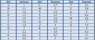
There are three main parameters that characterize a capacitor: the nominal capacity, tolerance and nominal voltage. In most cases, two marking methods are used - alphanumeric and numeric.
In the first case, the letter denotes the capacitance value (μ, nF, pF) and plays the role of a decimal point. For example, if a non-polar capacitor is marked 1 μ, then it is a part with a capacity of 1 μF, and the inscription 3μ3 means 3.3 μF.
A letter encoding can be used to indicate tolerance; its decoding is presented in Figure 8.
Figure 8. Decoding of letter marking of tolerance
The operating voltage of the capacitance can also be indicated by a letter code; its decoding is given below.
Table: explanation of the letter marking of permissible voltage
Small containers, for example, in SMD version, are usually marked with a three-digit digital code.
Three-digit digital code for capacity parameter
In order not to remember all the table values, use the following decoding rule: the values are given in picofarads, the first and second values are the mantissa, the third is a power with a base of 10. For example, the inscription 331 will mean 330 pF (33*10).
Polar and non-polar capacitors - what is the difference
All kinds of capacitors, used today almost everywhere in electronics and electrical engineering, contain various substances as dielectrics
However, with regard specifically to electrolytic capacitors, in particular also tantalum and polymer ones, when they are included in the circuit, it is important to strictly observe polarity. If such a capacitor is connected incorrectly to the circuit, it will not be able to work normally.
These capacitors are therefore called polar capacitors. What is the fundamental difference between a polar capacitor and a non-polar one? Why is it that some capacitors do not care how they are included in the circuit, while for others it is fundamentally important to maintain polarity?
It will be interesting Formula for calculating capacitor resistance
Let's try to figure this out now. The point here is that the manufacturing process for electrolytic capacitors is very different from, say, ceramic or polypropylene. If for the latter two both the plates and the dielectric are homogeneous in relation to each other, that is, there is no difference in the structure at the plate-dielectric interface on both sides of the dielectric, then electrolytic capacitors (cylindrical aluminum, tantalum, polymer) have a difference in the structure of the dielectric transition -plating on both sides of the dielectric: the anode and cathode differ in chemical composition and physical properties.
When an electrolytic aluminum capacitor is made, they do not simply roll up two identical foil plates lined with electrolyte-impregnated paper. On the side of the anode plate (to which + is applied) there is a layer of aluminum oxide applied to the etched surface of the foil in a special way. The anode is designed to give electrons through an external circuit to the cathode during the charging of the capacitor. The negative plate (cathode) is simply aluminum foil; during the charging process, electrons come to it through an external circuit. The electrolyte here serves as a conductor of ions.
Polar and non-polar capacitors.
The same is the case with tantalum capacitors, where tantalum powder serves as the anode, on which a film of tantalum pentoxide is formed (the anode is connected to the oxide!), which functions as a dielectric, then there is a layer of semiconductor - manganese dioxide as an electrolyte, then a silver cathode, from which electrons will leave during the discharge process.
Polymer electrolytic capacitors use a lightweight conductive polymer as the cathode, but otherwise the processes are similar. The essence is oxidation and reduction reactions, like in a battery. The anode is oxidized during the electrochemical discharge reaction, and the cathode is reduced.
When an electrolytic capacitor is charged, there is an excess of electrons at its cathode, on the negative plate, imparting a negative charge to this terminal, and at the anode, a lack of electrons, giving a positive charge, thus obtaining a potential difference. If a charged electrolytic capacitor is connected to an external circuit, then excess electrons will run from the negatively charged cathode to the positively charged anode, and the charge will be neutralized. In the electrolyte, positive ions move at this moment from the cathode to the anode.
If such a polar capacitor is connected incorrectly to the circuit, then the described reactions will not be able to proceed normally, and the capacitor will not work normally. Non-polar capacitors can operate in any connection, since they have neither an anode, nor a cathode, nor an electrolyte, and their plates interact with the dielectric in the same way as with the source.
Capacitor polarity.
But what if you only have polar electrolytic capacitors at hand, but you need to connect the capacitor to a current circuit with changing polarity? There is one trick for this. You need to take two identical polar electrolytic capacitors and connect them together in series with terminals of the same name. You will get one non-polar capacitor from two polar ones, the capacitance of which will be 2 times less than each of its two components.
It will be interesting What is a variable capacitor
On this basis, by the way, non-polar electrolytic capacitors are made, in which an oxide layer is present on both plates. For this reason, non-polar electrolytic capacitors are significantly larger than polar capacitors of similar capacity. Based on this principle, electrolytic starting non-polar capacitors are also manufactured, designed to operate in alternating current circuits with a frequency of 50-60 Hz.
Polar and non-polar capacitor