How to determine the rotation speed of an electric motor
The rotation speed of an asynchronous electric motor is usually understood as the angular frequency of rotation of its rotor, which is shown on the nameplate (on the motor nameplate) as the number of revolutions per minute. A three-phase motor can also be powered from a single-phase network; to do this, it is enough to add a capacitor in parallel to one or two of its windings, depending on the network voltage, but this will not change the design of the motor.
So, if the rotor under load makes 2760 revolutions per minute, then the angular frequency of this motor will be equal to 2760 * 2pi/60 radians per second, that is, 289 rad/s, which is not convenient for perception, so the sign simply says “2760 rpm” min". In relation to an asynchronous electric motor, this is the speed taking into account slip s.
The synchronous speed of this motor (without taking into account slip) will be equal to 3000 revolutions per minute, since when the stator windings are powered by a mains current with a frequency of 50 Hz, every second the magnetic flux will make 50 complete cyclic changes, and 50 * 60 = 3000, so This turns out to be 3000 rpm - the synchronous speed of an asynchronous electric motor.
In this article, we will talk about how to determine the synchronous rotation speed of an unknown three-phase asynchronous motor simply by looking at its stator. By the appearance of the stator, by the location of the windings, by the number of slots, you can easily determine the synchronous speed of the electric motor if you do not have a tachometer at hand. So, let's start in order and look at this issue with examples.
3000 rpm
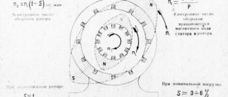
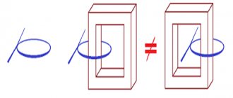
About asynchronous electric motors (see - Types of electric motors) it is customary to say that a particular motor has one, two, three or four pairs of poles. The minimum is one pair of poles, that is, the minimum is two poles. Take a look at the picture. Here you see that the stator contains two series-connected coils for each phase - in each pair of coils, one is located opposite the other. These coils form a pair of poles on the stator.
One of the phases is shown in red for clarity, the second in green, and the third in black. The windings of all three phases are arranged in the same way. Since these three windings are powered in turn (three-phase current), then for 1 oscillation out of 50 in each phase, the stator magnetic flux will turn once a full 360 degrees, that is, it will make one revolution in 1/50 of a second, which means 50 revolutions will be completed in give me a sec. So it turns out to be 3000 rpm.
Thus, it becomes clear that to determine the synchronous speed of an asynchronous electric motor, it is enough to determine the number of pairs of its poles, which is easy to do by removing the cover and looking at the stator.
Divide the total number of stator slots by the number of slots per section of the winding of one of the phases. If you get 2, then you have a motor with two poles - with one pair of poles. Therefore the synchronous frequency is 3000 rpm or approximately 2910 including slip. In the simplest case, there are 12 slots, 6 slots per coil, and 6 such coils - two for each of the three phases.
Please note that the number of coils in one group for one pair of poles may not necessarily be 1, but also 2 and 3, however, for example, we considered the option with single groups for a pair of coils (we will not focus on winding methods in this article).
1500 rpm
To obtain a synchronous speed of 1500 rpm, the number of stator poles is doubled so that in 1 oscillation out of 50 the magnetic flux would make only half a revolution - 180 degrees.
To do this, 4 winding sections are made for each phase. Thus, if one coil occupies a quarter of all slots, then you have a motor with two pairs of poles formed by four coils per phase.
For example, 6 slots out of 24 are occupied by one coil, or 12 out of 48, which means you have a motor with a synchronous speed of 1500 rpm, or taking into account sliding, approximately 1350 rpm. In the photo shown, each winding section is made in the form of a double coil group.
1000 rpm
As you already understand, to obtain a synchronous frequency of 1000 revolutions per minute, each phase already forms three pairs of poles, so that in one oscillation of 50 (hertz) the magnetic flux would turn only 120 degrees, and would turn the rotor accordingly.
Thus, a minimum of 18 coils are installed on the stator, with each coil occupying a sixth of all slots (six coils per phase - three pairs). For example, if there are 24 slots, then one coil will occupy 4 of them. The resulting frequency, taking into account slip, is about 935 rpm.
750 rpm
To obtain a synchronous speed of 750 rpm, it is necessary that three phases form four pairs of moving poles on the stator, this is 8 coils per phase - one opposite the other - 8 poles. If, for example, for 48 slots there is a coil for every 6 slots, you have an asynchronous motor with a synchronous speed of 750 (or about 730 taking into account sliding).
500 rpm
Finally, to obtain an asynchronous motor with a synchronous speed of 500 rpm, 6 pairs of poles are needed - 12 coils (poles) per phase, so that for each oscillation of the network the magnetic flux rotates 60 degrees. That is, if, for example, the stator has 36 slots, while there are 4 slots per coil - you have a three-phase motor with 500 rpm (480 including slip).
See also: How to distinguish an induction motor from a DC motor
Andrey Povny
General statements
In fact, the number of poles is always an even number (because of this, it is pairs of points that are counted, and not individual elements). In modern asynchronous electric motors, two types of winding are implemented:
Read also: Why are physical exercises needed in class?
- concentrated;
- distributed.
Concentrated winding is suitable for brushless motors. You can easily change the number of antipodes by changing the connection of the coils. The six-winding stator allows two key connection types. One has vengeance on two sides, the other on four or eight. However, changing the number of poles of a finished motor to four or eight is unwise. Distributed winding, which is often used to provide 12 points on a nine-slot stator, is suitable for induction motors. In this case, the quantity is selected even before starting to wind the motor.
Although small motors typically have four poles, two-pole motors are also used for high-speed applications requiring 50 or 60 revolutions per second. Before brushless motors were introduced, a technique was once used to change the number of poles in squirrel cage induction power units. The basis of the method involves changing the connection type of complex windings, which cannot be classified as a distributed coil or a concentrated winding. This method was an attempt to allow operation at two different speeds by changing the synchronous speed. Motor models with coils of this variety are called split-side motors.
Connecting an asynchronous motor to a single-phase network
Let us turn to the design of a three-phase asynchronous motor. As we know, there are 3 working phases of the engine, and there are also 3 terminals for connecting them. And in a single-phase household network of 220 Volts there are only two wires - phase and zero. What should I connect to the third terminal of the motor? If we connect a branch from any of these two wires to it, then we will simply get a short circuit with all the ensuing consequences.
The solution is to connect such a branch through a capacitor. The word “capacitor” is translated into Russian as “storage”. As you know, it works on the “charge-discharge” principle. That is, a capacitor connected to the network accumulates charge for some time, and then, when discharged, releases it back into the network. The time during which the capacitor accumulates charge is quite enough for the phase from which it is powered to “move” forward, to move in time. By moving, the phase seems to “free up space” for the discharge that the capacitor will produce, and eliminates the possibility of a “short” circuit. Due to the fact that the capacitor “shifts” the phases by its operation, it is called phase-shifting. You can read more about the operation of a capacitor in an alternating current circuit in this article. This creates the third wire necessary to connect the motor.
Connection diagrams for a single-phase network
Everything is quite simple here. We have to connect a capacitor between two phases. In a star scheme it will look like this.
Read also: Brands of turnout crosses
In order to change the rotation of the motor, we just need to swap phase (L) and zero (N) places.
Read also: Pig weight table by measurements
Well, the same thing applies to the “triangle” connection diagram.
How to choose a capacitor
When selecting a capacitor, you need to remember that it has two characteristics: the voltage for which it is designed and its electrical capacitance. The rule for selecting voltage can be expressed in simple words: the operating voltage of the capacitor indicated on its body must be greater than the operating voltage of the network into which the motor is connected. More precisely, this rule is expressed by the formula:
It may well be that the resulting value will be intermediate. That is, one for which capacitors are not produced. For example, for a 220 V network, the formula gives 311.13 V. Capacitors were not produced for this voltage. Then the capacitor is selected to the nearest value upward. In our case, you can take a capacitor of 380 Volts or more.
Capacitor capacitance calculation
The capacitor capacity is calculated using a formula that takes into account the connection diagram of the motor windings. The fact is that when calculating capacity, not only the operating voltage of the network is taken into account, but also the current flowing through the motor windings. An important role is also played by the fact that when the engine starts, a so-called starting current arises in the windings, which is much greater than the operating current of the engine. And since the operating current of the motor depends on the winding circuit, it is natural that the starting current will also depend on this circuit.
So, the formula for calculating a capacitor is:
Where
C – the required capacitance of the capacitor, µF
K – coefficient depending on the winding connection diagram
IN – rated motor current, Amperes
Table for selecting a circuit breaker based on load power
Table of consumption and current of the circuit breaker according to the power of devices
It can be seen that the manufacturer recommends different time-current characteristics for different electrical appliances. Where the load is purely active (different types of heaters), the characteristics of the machine “B” are recommended. Where there are electric motors - “C”. Well, where powerful engines with difficult starting are used - “D”.
The time-current characteristic D is not included in this table because it is not for domestic use. More details about starting engines are described in the article about connecting an electric motor through a magnetic starter. And also about turning on the solid-state relay.
Asynchronous electric motors
In previous sections, we discussed why AC motors are also called induction motors, or squirrel wheel motors. Next, we will explain why they are also called asynchronous electric motors. In this case, the relationship between the number of poles and the number of revolutions made by the rotor of the electric motor is taken into account.
The rotation frequency of the magnetic field is generally considered to be the synchronous rotation frequency (Ns). The synchronous speed can be calculated as follows: line frequency (F) multiplied by 120 and divided by the number of poles (P).
If, for example, the mains frequency is 50 Hz, then the synchronous speed for a 2-pole electric motor is 3000 rpm.
The synchronous speed decreases as the number of poles increases. The table below shows the synchronous speed for different numbers of poles. Synchronous speed for different number of poles
| Number of poles | Synchronous speed 50 Hz | Synchronous speed 60 Hz |
| 2 | 3000 | 3600 |
| 4 | 1500 | 1800 |
| 6 | 1000 | 1200 |
| 8 | 750 | 900 |
| 12 | 500 | 600 |
Circuit breaker current
Automatic currents come from the following series:
0,5, 1, 1,6, 2, 3,15, 4, 5, 6, 8, 10, 13, 16, 20, 25, 32, 40, 50, 63.
The denominations most often used in everyday life are highlighted in bold. There are other denominations, but we won’t talk about them now.
This current for the circuit breaker is rated. If it is exceeded, the switch will turn off. True, not immediately, as stated below:
Electric motor parameters: table
| Parameter name | Unit | Note |
| Type | ||
| Rated power | Kilowatt | |
| Rated current | Ampere | For three-phase electric motors depends on the type of winding connection |
| Rated voltage | Volt | |
| Power factor (efficiency) | ||
| Efficiency factor (cos ϕ) | % | |
| Rated rotation speed | Revolutions per minute |
But sometimes the sign is missing or impossible to read. During operation, the engine is painted several times, often along with the nameplate. Therefore, it is necessary to determine its parameters by measurement.
Electric motors as part of gearmotors
Electric motors have long been included in various gearmotors. They find their application in three-stage MTs3U type. and in two-stage type MTs2U. Electric motors have almost 90% efficiency and do not require constant maintenance. An important parameter is the exceptional environmental friendliness of the electric motor; there are no harmful emissions at all, which makes it indispensable for indoor installation. In short, electric motors are currently recognized as 3 or even 4 times more efficient than traditional internal combustion engines.
But sometimes, in the event of an electric motor failure, the buyer finds out that absolutely no accompanying documentation is attached to it. Marking nameplates, even if they have been preserved, may be in a worn-out, shabby state, so that it is simply impossible to see anything on them. How, then, can you determine the engine power and its speed? Here are some step-by-step tips to help you do this.
It should be borne in mind that the number of revolutions refers to the so-called asynchronous speed. Synchronous speed is the speed of rotation of the magnetic field. Asynchronous speed is slightly lower than synchronous due to the presence of mass in the rotating element, as well as the influence of friction forces, which can significantly reduce the efficiency of the motor. However, in practice these differences are almost never of decisive importance.
There are currently 3 main categories of asynchronous electric motors on the market. The first category of the catalog is motors operating at 1000 rpm. In practice, this number is about 950-970 revolutions, but for clarity, it is still rounded to the nearest thousand. The second category is motors producing 1500 rpm. This is also rounded as the actual range is 1430-1470. The third is 3000 rpm. Although in reality such a motor produces 2900-2970 rotations.
How to find out the speed of an electric motor yourself
Often, when buying an electric motor secondhand, the car owner (and not only) subsequently discovers that there is no documentation for it. In this case, as a rule, you have to independently determine the speed of the electric motor, and many, as practice shows, do not know how to do this. This article will tell you how to determine the speed of an electric motor yourself and what you should know.
Step-by-step instructions for determining speed
1. Today, asynchronous electric motors are divided into three groups, each of which indicates an individual rotation of the rotor per minute. The first group is electric motors that make 1000 revolutions per minute. It is worth immediately noting that this figure is slightly exaggerated, since the motor is asynchronous.
As a rule, it makes about 950-970 revolutions, but for convenience, experts decided to round such numbers. The second group includes engines whose rotor revolutions number 1,500 per minute. This figure is also rounded; in fact, the electric motor makes 1430-1470 revolutions per minute.
The third group of asynchronous electric motors is the group that includes a part whose rotor rotates around itself three thousand times in one minute. The real speed figure is 2900-2970.
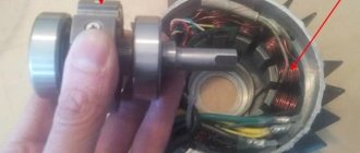
2. In order to determine the speed of the electric motor, you first need to identify which of the above groups it belongs to. To do this, open one of its covers and find the winding coil underneath. Remember, such a coil can consist of one part or several, in particular three or four. Among other things, know that there can be several such coils in an electric motor. You only need one, which requires the least amount of effort to look at.
3. Attention! The coils are connected to each other by certain details, which sometimes make it difficult to view the necessary information. Under no circumstances should anything be disconnected from each other. Take a close look at the part you have chosen and try to approximate the size of the coil relative to the stator ring.
4. To find out the speed of the electric motor, this distance does not need to be determined accurately. Approximate calculations will work for you.
If the size of the coil approximately covers half of the stator ring, then the rotor rotation speed is three thousand revolutions per minute.
If the size of the coil covers approximately a third of the ring itself, the electric motor will belong to the second group and, therefore, the number of revolutions it can make will not exceed 1500 per minute.
When the size of the coil is equal to one fourth in relation to the ring, the speed of the electric motor will be 1000 revolutions per minute and, accordingly, the engine will belong to the third group.
Do not forget that the indicated figures are just an approximate picture of rotation; in reality they may differ and this depends on many factors.
These articles will also be useful to you:
Now watch this helpful video:
Many have probably seen and already have such wonderful accessories made from kanzashi flowers in their wardrobe. This article will teach you the technique for making them. Flowers made from satin ribbons - kansasi.
In this lesson you will learn what modular origami is and for your study a diagram of the assembly of a double swan will be presented, which you can assemble with your own hands.
For owners of garden plots, greenhouses, garages and any premises that need insulation. Having loaded such a stove once with firewood, you can then not approach it at all for a couple of days.
Nowadays there are more and more lollipops, Twixes and other overseas products on sale. Why don’t you make a cockerel on a stick today and please your child with such a non-standard gift.
How to prepare a product for smoking in camping, home and country conditions, select smoking wood, make homemade smokehouses, smoke a product, and do it all with your own hands.
Electric motor parameters: winding connection type
This is a very important parameter of a three-phase electric motor. All six terminals of the beginnings and ends of the windings are brought out into the engine bar. They can be connected either in a star or in a triangle.
Next to triangle/star
The plate indicates the rated voltage
– “220/380 V”
. This means that when a three-phase current with a voltage of 380 V is connected to the network, the motor windings must be connected in a star. An error in the connection will result in motor failure.
The rated current is also indicated as a fraction. In the described case, the value specified in the denominator is required.
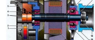
Components of an electric machine
The basis for an electric machine is the rule of electrical induction with magnetic induction. Such a device includes a stator or, as it is called, a constant part (typical for asynchronous, synchronous machines of variable current) or an inductor (for devices of constant current) and a rotor, it is called an active or moving part (for asynchronous and synchronous machines of variable current) or an armature (constant current devices). Magnets (of a constant state) are actively used as a constant part for current machines with low power.
Mechanical characteristics of the engine
The mechanical characteristic is the dependence of torque on slip at constant voltage and network frequency.
In Fig. Figure 19 shows the mechanical characteristics of the engine. When starting, the engine develops a starting torque MP
(S = 1); if the starting torque is greater than the resistance moment of the working machine MS
, then the engine rotor will turn and the engine will operate at point a of the characteristic.
Increasing the moment of resistance of the working machine MS
, we will increase the slip, and point a will begin to move along the characteristic to point At point 1, the engine develops maximum torque, slip corresponding to the maximum torque, which is called critical - SKR
.
MC
increases above the torque
Mm
, the slip quickly increases and the motor rotor stops (the motor “rolls over” occurs).
The ratio of the starting torque to the nominal is called the starting torque multiple:
Rice. 19. Mechanical characteristics of an asynchronous motor
The starting torque multiplicity is indicated in the reference data catalogs; it must be greater than 0.9.
The ratio of the maximum torque to the nominal torque is called the overload capacity of the motor:
The overload capacity is indicated in the catalogues. It is usually in the range of 1.7-2.5. The mechanical characteristic has two characteristic branches: branch ( A-B
) is the stable part of the characteristic (with increasing slip, the engine torque increases); branch ( B
-
C
) - unstable part of the characteristic (with increasing slip, the engine torque decreases). If an active resistance is introduced into the circuit of a motor with a wound rotor, then the maximum torque, without changing in value, moves to the region of higher slips (Fig. 20, mechanical characteristic II). You can select such a resistance in the rotor circuit that the maximum torque will occur at start-up.
Rice. 20. Mechanical characteristics of an asynchronous motor with a wound rotor
Curve I for normal motors shows that the asynchronous motor has a rigid speed characteristic. An asynchronous motor with a wound rotor with resistance in the rotor circuit has a softer characteristic (curve II). By increasing the resistance in the rotor circuit, you can shift the maximum torque and make it equal to the starting torque.
Great Encyclopedia of Oil and Gas
Number - pairs - pole - stator
The number of stator pole pairs is always equal to the number of rotor pole pairs. [1]
If the numbers of pairs of stator and rotor poles are equal, and the speeds of rotation of the fields are the same (synchronous mode), then a constant electromagnetic attraction of opposite poles of the stator and rotor occurs (Fig. 4 - 2), which causes the appearance of an electromagnetic torque. This torque, called synchronous, is on average zero if the rotor speed is different from synchronous. Therefore, a permanent magnet-only synchronous motor has no starting torque. [3]
When the number of stator pole pairs is greater than one, this process is repeated 1/2 times. [4]
The synchronous speed of the field sos is determined by the frequency of the supply network and the number of pole pairs of the stators of the machine. It is assumed that there is one power source, and the number of pole pairs for the three stators is the same. [5]
An asynchronous motor with the same number of pairs of stator poles as a synchronous motor or a DC motor is used as an accelerating motor. [6]
It follows that the rated speed of an asynchronous motor can be changed by changing the number of stator pole pairs. Engines that use this method of changing the speed are called multi-speed. [7]
In Fig. 10.5, a shows a detailed diagram of a single-layer winding of a four-pole stator (the number of pairs of stator poles p2), on which the sections are conventionally depicted as one turn. The diagram shows three phase windings: A-X, B-Y, C-Z, each consisting of two series-connected coil groups, each group having two sections. [8]
The number of revolutions of the magnetic field per minute is determined by the formula: n - -, where P is the number of pairs of stator poles, / is the current frequency. [10]
Since the speed of rotation of the flow mainly determines the number of revolutions of the rotor of an asynchronous motor [see formula (187)], we come to the conclusion that the number of revolutions of an asynchronous motor at a given frequency of alternating current is almost exactly inversely proportional to the number of pairs of stator poles. [eleven]
The three-phase stator winding of an alternator is similar to the stator winding of an asynchronous motor. The number of stator pole pairs is always equal to the number of rotor pole pairs. [12]
If the clutch is excited by a permanent magnet, then the torque is adjusted by changing the air gap, but if there is a winding on the stator, then the excitation current is varied. The damping effect of the coupling is proportional to the number of pairs of stator poles, the volume of the hysteresis layer of the rotor and the specific losses in it during the magnetization reversal cycle. The magnitude of the torque is practically independent of the rotor speed. [14]
Determining the exact quantity
Above, we have already described how to adjust speed indicators using the number of pole pairs of the motor. How can you independently determine the exact number of these pairs?
The rotation speed of an asynchronous type motor in most situations is interpreted as the angular speed of its rotor. As a rule, the exact value of the indicator is indicated on a technical plate mounted on the side of the engine housing. The indicator is expressed in revolutions per 1 minute.
Three-phase power units support the possibility of power supply from networks with one operating phase, but to implement such an idea, you need to connect a capacitor. It’s not easy to do this, but simultaneously one or more of its windings, focusing on the voltage level of the power supply network. This will not fundamentally affect the design of the engine.
If during operation the rotor, under load, rotates 2760 times in 1 minute, then its angular frequency will be equal to 289 radians per second. It's quite easy to calculate:
2760 * 2pi/60rad.
The resulting indicator is more technical and inconvenient for the average user to understand. That is why the performance indicators of the motor are indicated simply and clearly - in revolutions per minute.
The level of coordinated speed of such a motor (without taking into account such an important value as sliding) is equal to 3000 rotations. This is due to the fact that the power supply to the starter windings of the network has a frequency of 50 Hz. Every working second, the magnetic flux will carry out 50 full changes. Based on this - 50 * 60 = 3 thousand. The effective indicator is the synchronous speed of an asynchronous type electric motor.
Next, we will look at another method for determining the speed level of a conventional three-phase unit by conducting a visual inspection of the stator. By assessing the appearance of the stationary part, the location of the copper windings and the exact number of slots, it is possible to easily accurately determine the number of motor revolutions. This feature is especially useful if you do not have a measuring device such as a tachometer.
Additionally
Electrical wear resistance (switching) - the number of operating cycles (on-off) under load for which the protective automatic equipment is designed. Based on this value, the service life of the device is estimated. The optimal choice is a circuit breaker, RCD or automatic machine that can withstand up to 10,000 operating cycles.
Mechanical wear resistance - the number of operating cycles without load. This parameter is always greater than the previous characteristic, but in practice it is not taken into account.
Methods for determining the characteristics of an electric motor
To determine which of these groups the engine belongs to, you do not need to disassemble it, as some experts advise, in order to secure a work order. The fact is that disassembly of an electric motor can only be carried out by a sufficiently qualified master. In fact, it is enough to open the protective cover (another name is the bearing shield) and find the winding coil. There may be several such coils, but one is enough. If a coupling half or pulley is attached to the shaft, you will also need to remove the lower shield.
If the coils are connected using parts that interfere with viewing the information, these parts must not be disconnected under any circumstances. You need to try to determine by eye the ratio of the size of the coil and the stator.
The stator is the stationary part of the electric motor, while the moving part is called the rotor. Depending on the design features, either the coil itself or magnets can act as a rotor.
If the coil covers half of the stator ring, such an engine belongs to the third group, that is, it is capable of delivering up to 3000 revolutions. If the size of the coil is a third of the size of the ring, this is a motor of the second type; accordingly, it is capable of developing 1500 rpm. Finally, if the coil only covers a quarter of the ring, it is type 1. The electric motor develops a power of 1000 rpm.
There is another way to determine the rotation speed of the rotor shaft. To do this, you also need to remove the cover and find the upper part of the winding. The location of the winding sections determines the speed. Typically the outer section occupies 12 slots. If you count the total number of slots and divide by 12, you can get the number of poles. If the number of poles is 2, the motor has a rotation speed of about 3000 rpm. If there are 4 poles, this corresponds to 1500 rpm. If 6, then 1000 rpm. If 8, then 700 rpm.
The third way to determine the number of revolutions is to carefully examine the tag on the engine itself. The number on the marking at the end corresponds to the number of poles. For example, for marking AIR160S6, the last digit 6 indicates how many poles the coil uses.
The easiest way to measure the speed is with a special tachometer. But due to the narrow specialization of application, this method cannot be considered as generally available. Thus, even if no technical documentation has been preserved, there are at least 4 ways to determine the speed of an electric motor.
How to determine the rotation speed of an electric motor?
It is obvious that the correct operation of any electric machine requires compliance of such an important technical parameter as the rotation speed with the operating conditions.
All the main parameters of an asynchronous electric motor are indicated by the manufacturer on a metal tag - nameplate attached to its body. And of course, the given technical data necessarily contains information about the rotation speed at rated load.
However, in practice, there are quite often cases when it is necessary to determine the speed of an engine with a missing nameplate or with unreadable - erased inscriptions on it.
Of course, in such cases, an experienced electric drive technician will certainly be able to determine the rotation speed, but novice electricians involved in servicing electrical equipment may have some difficulties in resolving this issue.
The easiest way to determine the rotation speed of the shaft of a working “asynchronous machine” is with a tachometer. But, given that due to the narrow specificity of use, the presence of this measuring device is very rare, this method is not considered here.
We hope the method suggested below will be useful. It is applicable for small and medium power asynchronous electric motors with single-layer stator windings.
So, in our case, determining the rotation speed of an electric motor involves inspecting its stator winding. Therefore, you will need to remove the cover (bearing shield) from the engine. If a pulley or coupling half is attached to its shaft to transmit motion, we recommend removing the rear shield.
Having removed the cover and the fan impeller from the shaft, unscrew the screws, remove the rear bearing shield, and then inspect the end part of the stator winding. Next, you need to count the number of slots occupied by sections of one coil.
The total number of core slots divided by the number of slots occupied by sections of one coil (quotient) will be the number of poles. Knowing its value, we determine the rotation speed of the asynchronous electric motor:
2 – 3000 rpm; 4 – 1500 rpm; 6 – 1000 rpm.
Here it is worth considering one feature of asynchronous motors - the discrepancy between the speed of rotation of the magnetic field and the rotation of the rotor, so the speed can be 940 rpm instead of 1000 or 2940 rpm instead of 3000.
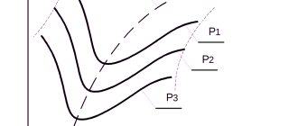
As you can see, this method of determining the rotation speed from the winding is not particularly complicated, however, it can be simplified; You will need to visually determine which part of the circumference of the stator core is occupied by sections of one coil:
The ½ part of the engine stator core occupied by sections of one coil indicates its rotation speed is 3000 rpm, ⅓ – 1500 rpm, ¼ – 1000 rpm.
>How to determine the power and speed of an electric motor without disassembling it.
How to find out the characteristics of an electric motor without markings.
Calculation of the number of revolutions of an asynchronous motor
A common motor in machine tools and lifting devices is a squirrel-cage motor, so the calculation example should be taken for this type. The mains voltage is supplied to the stator winding. The windings are offset from each other by 120 degrees. The resulting electromagnetic induction field excites an electric current in the winding. The rotor begins to operate under the influence of EMC. The main characteristic of engine operation is the number of revolutions per minute. We calculate this value:
n = 60 f/p, rpm;
where f is the network frequency, hertz, p is the number of stator poles (in pairs).
There is a plate with technical data on the motor housing. If it is not there, then you can calculate the number of revolutions of the equipment shaft yourself using other available data. The calculation is made in three ways.
- The calculation of the number of coils, which is compared with the standards for different voltages, follows the table:
- Calculation of operating speed by pitch of winding diameter using the formula:
2 p = Z 1 / y, where 2p is the number of poles, Z 1 is the number of slots in the stator, y is the winding pitch.
Select the appropriate engine speed from the table:
- We calculate the number of poles based on the core parameters using the formula:
2p = 0.35 Z 1 b / h or 2 p = 0.5 D i / h,
where 2p is the number of poles, Z 1 is the number of grooves, b is the tooth size, cm, h is the height of the back, cm, D i is the diameter of the teeth, cm.
Based on the results of calculation and induction, the number of turns of the winding follows and is compared with the values of the motor according to the passport.
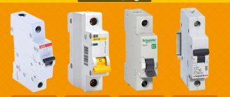
What is it and how does it work?
Automatic machines make life easier by protecting appliances from combustion. Sudden changes in network parameters cause short circuits or overloads, to which not every equipment is resistant. Small devices with conductors turn off a section during sudden changes in network indicators and save electrical appliances from imminent death.
Modular machines consist of blocks of the same size and functionality. Each part is 1 pole. 2-, 3- and 4-pole combinations are assembled. The number of poles of the circuit breaker depends on the parameters of the electrical network.
Modular machine design:
- electromagnetic coil;
- arc extinguishing device;
- contacts;
- bimetallic plate;
- screw terminals;
- release mechanism;
- pen.
The designs are practically indistinguishable. Cost and reliability depend on the manufacturer, who, in turn, uses more or less high-quality materials. The devices may have different electromagnets and differently designed thermal protection, an arc extinguishing system, other elements are the same.
Rotation speed measurement
Measuring the speed of rotation of shafts, gears, wheels and other elements is usually carried out using electronic tachometers. A typical diagram of an electronic tachometer is shown in Fig. 26.
Tachometers measure rotation speed n with dimension . Already the first glance at this dimension makes it clear that the tachometer must perform two types of measurements simultaneously. First, measure the number of revolutions (shaft, gear, wheel, etc.). Secondly, measure time. To perform such measurements, the electronic tachometer (Fig. 26) contains an electronic stopwatch, a photoelectric sensor and a LU logic device.
We got acquainted with the structure and operation of an electronic stopwatch in the previous section. Now let's get acquainted with the device and operation of the photoelectric sensor. It consists of a LED - an LED emitter, a photodiode - an FD receiver and an electrical pulse shaper FS1. The LED emits light onto the photosensitive surface of the photodiode of the PD receiver. In this case, the resistance of the photodiode drops. If an opaque material is placed on the light line between the LED and the PD photodiode, the resistance of the PD photodiode will increase sharply.
Rice. 26. Functional diagram of an electronic tachometer
This property of a photoelectric sensor is widely used in engineering and measurement. To measure the rotation speed, a disk 1 with holes rotating on shaft 2 is placed between the optocoupler (LED emitter and photodiode receiver) (Fig. 26). As the shaft rotates, 2 holes in the disk will interrupt the light flow between the LED LED and the PD photodiode. In this case, the resistance of the PD photodiode will continuously change synchronously with the shaft rotation frequency. The FS1 pulse shaper responds to changes in the resistance of the photodiode, converting each of them into rectangular electrical pulses at its output, standard in voltage and duration (see Fig. 27, (a). The faster disk 2 rotates, the higher the pulse repetition rate at the output of the shaper FS1.
Now let's get acquainted with the operation of the logical device of the LU (Fig. 26). A logic device has two inputs and one output. The principle of its operation can be formulated as “2-I”. That is, if voltage is applied to both the first and second inputs of the logical device LU (the “2-I” condition is met), then there will also be voltage at its output. If there is no voltage at at least one of the inputs of the LU (condition two “AND” is not met), then there will be no voltage at its output. This principle of LU operation is well illustrated by the graphs presented in Fig. 27.
Rice. 27. Graphs of electrical pulses during operation of the electronic tachometer circuit, (A) – pulses at the output of the FS1 driver at point A; (B) – pulses of counting time periods (from the output of the dividing decade DD4); (B) – pulses at the output of the logical device (at the input to SchD1); (D) – pulses that reset the counting decades at the start of a new counting period
In the process of measuring the rotation speed of shaft 2 with a tachometer (Fig. 26), electrical pulses are generated at the output of the FS1 driver at point (A) with the repetition rate of the holes in disk 1. These pulses are supplied to the first input of the logical device LU. At the same time, pulses of counting time periods arrive at the second input of the LU at point (B) from the output of the dividing decade DD4.
Looking at Fig. 27. It is not difficult to see that the “2-I” condition can be periodically fulfilled only at the moment when a voltage of 5 volts is applied to the second input of the LU at point (B) for 1 second. At the same time, electrical pulses caused by the rotation of disk 2 arrive from the output of the FS1 driver to the first input of the LU at point (A). Thus, at the output of the logical device of the LU at point (B), rectangular electrical pulses are formed, which in appearance repeat the pulses coming from the FS1 driver. They arrive at the counting decades of the SChD, which is why this mode is called “counting”.
After the pulse counting period, during the next period of time lasting 1 second, the voltage at the second input of the LU becomes zero. At the output of the LU, the voltage also becomes zero, since the “2-I” principle is not fulfilled. Accounting is not possible. On the counting decades, the counting result is displayed for one second. This mode is called "indication".
After the “indication” mode, the automatic control device for resetting the UUS (Fig. 26) generates at its output at point (D) a short electrical pulse, which is supplied simultaneously to the zeroing inputs of all counting decades. The counting decades are reset to zero and a new counting mode begins. Thus, the “counting” and “indication” modes are repeated cyclically.
To determine the rotation speed of a shaft, gear, etc. from the readings of an electronic tachometer, use the formula:
(2.18)
where: N – counting result on the counting decade displays; k – number of holes in the sensor disk; t – counting time period.
For example, the number 2400 was displayed on the counting decade displays of the electronic tachometer. There are 80 holes in the sensor disk. The counting time period is 1 second. In this case:
rps
If 60 holes are made in the circumference of the disk, and the counting period is equal to 1 second, then, taking into account the fact that there are 60 seconds in 1 minute, the electronic tachometer will show the rotation speed in the dimension .
The absolute error Δn of measuring the speed of an electronic tachometer is calculated using the following formula:
, (2.19)
where: Δtmeas – absolute error in the duration of the time pulse (from the instability of the reference frequency generator); nх – measured rotation speed; tmeas – duration of the time pulse (in our example it is equal to 1 second).
The relative error in measuring the speed with an electronic tachometer is determined by the formula:
(2.20)
For example, it is necessary to determine the absolute and relative errors in measuring the number of revolutions with an electronic tachometer if it shows the value of the measured rotation speed nx = 1000 rpm, and the absolute error in the duration of the time pulse Δtmeas = 0.0001 s. Using formula (2.19), we determine the absolute error in measuring the speed with an electronic tachometer:
Tags
stator windings mains stator. in the stator is laid on the stator. the stator flux is one per stator. stator slots divide the stator poles increase on the stator four for example the stator has if the rotor is an auxiliary rotor. the name of the rotor. the quality of the rotor can the shaft of the rotor part. rotation of the rotor rotations of the rotor which indicator of the rotor. with direct current alternating current direct current Generated current and movement of currents movement of currents in movement of current variations of current in electric current in
division