The car's generator ensures that the battery charge is restored and power is supplied to all consumers connected to the on-board network. It does not store electricity like a battery, but continuously produces it while the engine is running. But while the internal combustion engine is not running, this unit does not work, and the function of powering the on-board network is performed by the battery.
The operation of a car generator resembles the operation of an electric motor, only in reverse. An electric motor receives energy and converts it into mechanical action, while a generator converts the mechanical rotation of the rotor into electrical energy.
Briefly, the principle by which a car generator works can be explained as follows: rotation of the rotor leads to the formation of a magnetic field, and it affects the stator winding. This leads to the emergence of an electric current in the latter, which is then supplied to power consumers connected to the vehicle’s on-board network.
Car generator: principle of operation, malfunctions
A break or short circuit in the field windings can be eliminated by rewinding. Other electrical faults are corrected by replacing the failed part.
Expert opinion
It-Technology, Electrical power and electronics specialist
Ask questions to the “Specialist for modernization of energy generation systems”
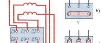
Car generator: principle of operation, device, connection diagram, purpose The triangle diagram provides for the connection of windings according to a different principle: 1st to 2nd, 2nd to 3rd, and 3rd, in turn, to 1st. Ask, I'm in touch!
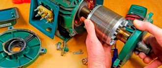
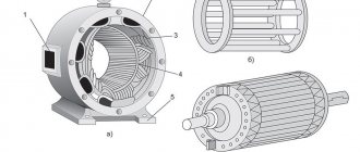
The device of a car generator
The autogenerator includes several components:
1 - rear bearing; 2 - rectifier block; 3 - slip rings; 4 - brush; 5 — brush holder; 6 - casing; 7 - diode; 8 — bearing sleeve; 9 - screw; 10 — back cover; 11 — impeller; 12 - screw; 13 - rotor; 14 — rotor winding; 15 — front cover; 16 — rotor shaft; 17 — washer; 18 - nut; 19 — pulley; 20 — front bearing; 21 — rotor winding; 22 - stator.
Rotor
The excitation winding is designed to create a magnetic field. To solve this problem, a weak electric current must be applied to it. Before starting the power unit, the battery supplies current to form a magnetic field. When the internal combustion engine is running and the speed reaches the required value, the generator will supply current to the excitation winding
What kind of lighting do you prefer?
Built-in Chandelier
The rotor is located inside the stator, sandwiched between the housing covers. The covers are equipped with seats in which rotor bearings are placed. In addition, the cover located on the drive pulley side has holes for ventilation.
Stator
1 - core; 2 - winding; 3 - groove wedge; 4 - groove; 5 - terminal for connection to the rectifier.
In a star connection, all the windings are connected together at one end at a common point. Their second ends serve as conclusions. The “triangle” circuit involves connecting the windings according to a different principle: the 1st to the 2nd, the 2nd to the 3rd, and the 3rd, in turn, to the 1st. In this case, the function of the terminals is performed by the connection points. Both diagrams are clearly shown in the figure.
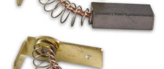
Brush block
The task of this component of the generator is to transmit electricity to the excitation winding. Structurally, the block is a housing with a pair of spring-loaded graphite brushes located in it. The latter are pressed against the slip rings with the help of springs, but are not rigidly fastened to them.
Voltage regulator
Diode bridge (rectifier block)
The task of this element is to convert the alternating current supplied to it into the direct current necessary to power the on-board network. Structurally, it consists of heat-removing plates, into which 6 diodes are mounted - 2 for each stator winding (on “+” and on “-”).
Technology for assembling and processing DC motor commutators
Materials of the dissertation - Pelipenko, Yaroslav Nikolaevich.
Increasing the accuracy of manufacturing electric motor parts using a portable machine module: abstract of dissertation. ... Candidate of Technical Sciences: 02/05/08 / Belgorod. state technol. University named after V.G. Shukhova. - Belgorod, 2006. - 21 p. Electrical machines and apparatus - Electrical machines - Electrical motors - Collectors - Grinding - Process design Mechanical engineering technology eliminating commutator runout.
https://search.rsl.ru/ru/record/01003289111
It is generally accepted that the history of electric machines begins with the creation by M. Faraday in 1821 of an electric motor, which was a permanent magnet around which a current-carrying conductor rotated. The creation of electric machines is based on the works of such scientists as: P. Barlow, F. Arato, D.K. Maxwell, E. Lenz, B.S. Jacobi and others. The first commutator electric motors were built in 1870 by the German scientist Z. Grolich. He took as a basis the previously completed work of the Italian scientist A. Pacinotti on the use of ring winding. An electric machine with a ring winding and a collector is usually called Pacinotti - Gramma (Fig. 1.1).
Rice. 1.1. Electric machine with a ring winding Pacinotti-Gram.
1 – ring anchor; 2 – ring closed winding; 3 – taps to collector plates; 4 – brushes; 5 – permanent electromagnets; 6 – pole pieces. In this machine, the commutator and winding were made of steel. The prototype of modern commutator DC motors was a machine created in 1973 by F. Gefner-Altenek and W. Siemens (Fig. 1.2). Its armature was shaped like a drum, and the windings and commutator were made of copper for the first time.
Rice. 1.2. Electric machine with drum armature. 1 – collector; 2 – anchor; 3-brush mechanism.
Beginning its history with machines in which electromechanical energy conversion was carried out in an electric field, in the 19th and 20th centuries. Electromechanics has made great strides. The power of the machines increased by 100 and 1000 times, the consumption of materials per unit of power was reduced by 10 - 100 times. Unique electric machines were created for various fields of technology, not only as power converters, but also as indicator devices for precision navigation and other automation systems. Recently, every day patent organizations around the world are issuing patents with the name “Electric machine”. In this regard, it is difficult to single out outstanding inventions from this stream, since too many unique electromechanical systems were created that made it possible to solve complex technical problems. The widespread introduction of electric motors into all spheres of human activity necessitates both an increase in design and technological designs, and an improvement in their operational and economic indicators. The high quality of electric motors, their operational reliability and reduced manufacturing labor intensity largely depend on a properly constructed technological process that corresponds to the level of modern technology, provided with the necessary technological equipment and tooling. The technology of electrical machine-building production is part of the general technology of mechanical engineering, the object of which is the production of electrical machines of the required quality, in the quantity established by the production program and in a given time frame at a minimum cost. The technological structure of electric motor manufacturing includes: production of blanks, production of parts, machine assembly, testing, painting, preservation and packaging. In the process of improving the design of DC electric motors, all components and parts underwent changes, in particular, the unit performing the switching function between the armature and the stator underwent serious changes. Over the course of a long time, different materials and design solutions were tested, resulting in a modern brush-collector unit. The reliability of electric motors largely depends on the manufacturing technology of its parts and assembly. The operation of the brush-collector unit is associated with the influence of three groups of factors associated with electromagnetic processes, physicochemical nature, sliding contact, mechanical influences and temperature heating. Factors of an electromagnetic nature include switching conditions: electromagnetic loads, voltages between adjacent plates, reactive emf, current overloads, largely determined by the adjustment of additional poles. Factors of the physico-chemical nature of the sliding contact are determined by the conditions of current collection (the state of the contact film on the surface of the collector) and the state of the environment. Factors of mechanical impact are determined by the technological and design features of the machine (weakening of compaction, eccentricity and ellipticity of the commutator, brand of brushes and commutator material, assembly and manufacturing technology, pressure on the brush, rotation speed). At the same time, the most dangerous causes of malfunction of the brush-collector unit remain those caused by the influence of mechanical factors. One of the main reasons for the mechanical impact that disrupts the operation of the brush-commutator assembly is the destruction of the brushes due to a violation of the cylindricality of the commutator, that is, the presence of protruding commutator plates, as well as sparking under the brushes and circular fire due to beating, ellipticity and eccentricity of the commutator. The labor intensity of its ongoing maintenance makes up the bulk of the cost of maintaining the engine as a whole. Especially labor-intensive: turning the collectors, eliminating the effects of circular lights and “envelopment” of copper in the inter-lamella spaces. Since these phenomena are fundamentally interrelated, a fundamental solution to the problem of reliability of the brush-commutator assembly lies in the comprehensive use of available reserves. In particular, this problem is very acute for traction motors for electric locomotives. In the traction motors of all newly designed electric locomotives, collector profiles made of copper-cadmium alloy (bronze) BrKd-1 are used. Compared to commercially used commutator copper with a silver additive (MS-1 alloy), this material reduces the wear rate of commutators and brushes by 2-2.5 times. It has a low coefficient of friction and high resistance to copper coating. The sliding pair of BrKd-1 alloy and brushes of the EG61A brand provide a range of at least 600 thousand km without turning the commutators of freight electric locomotives, and 0.8 - 1 million km for passenger locomotives. Change of brushes is required after 150 thousand km on freight locomotives and after 200 thousand km on passenger electric locomotives. And one more thing that needs to be done first is to increase the stability of the quality of EG-61A electric brushes. This brand is the best of the domestic ones for traction motors of mainline electric locomotives; in terms of its technical parameters - permissible current density, friction coefficient, mechanical strength - it is not inferior to, and in some respects superior to, electric brushes from leading foreign companies. However, in recent years, there has been instability in the technical characteristics of mass-produced electric brushes. Certain reserves for increasing the reliability of the brush-commutator assembly lie in the further improvement of its design and manufacturing technology. First of all, it is necessary to increase the surface electrical strength and tracking resistance of insulating parts - the fingers of the brush holder brackets, the insulating extension of the commutator cone collar. Modern electric locomotives are equipped with an adjustable ventilation system, and traction motors operate most of the time at a reduced flow rate of blown air to 1/3 of the nominal value. Unfortunately, this leads to insufficiently intensive removal of electrically conductive wear products from the brushes, their deposition on insulating parts and, with accompanying moisture, to surface electrical flashover. During operation, the electric motor heats up, especially its commutator. In some machines, the heating temperature of the collector reaches 200°C. Therefore, the design of the electric motor includes special cooling devices: air, water, hydrogen, etc. Regarding the collector, we can say that it is one of the most labor-intensive, complex and expensive components, which largely determines the service life of the electric machine. Structurally, the collector is one of its most critical components. It is the main transformative link in the operation of the machine. The commutator, together with the brush mechanism, plays the role of a rectifier in the operating mode of a DC machine as a generator and the role of an inverter in engine mode. The complexity of the collector design is explained, firstly, by the structure of the ring, consisting of a large number of copper plates alternating with micanite gaskets, and secondly, by the complex geometric shapes of the mating of metal and insulating parts, such as steel pressure cones, micanite cuffs and copper dovetails of the collector plates, and, finally, force phenomena arising under the influence of centrifugal forces and temperature changes. The operational requirements for the commutator are reduced to ensuring satisfactory operation of the sliding contact, that is, spark-free switching conditions in combination with low wear on the working surface of the commutator plates and a sufficiently long service life of the brushes. One of the main conditions that ensure satisfactory operation of the sliding contact is the tight fit of the brushes to the working surface of the commutator when it rotates at a given frequency. To ensure this condition, it is necessary that the working surface of the collector has a strictly cylindrical shape and the geometric axis of this cylinder coincides with the axis of rotation of the armature. To ensure good commutation, the commutator runout in the assembled machine should be no more than 0.02 mm for medium commutators and no more than 0.03 mm. If we take into account that half of this value is determined by the bearing clearance and the eccentricity of the bearing shields, then the allowable runout of the commutator remains 0.015...0.02 mm. Collector designs are constantly being developed and improved. Currently, there are dozens of design versions of collectors for electrical machines of low and medium power, as well as for large machines. According to the design and manufacturing technology, collectors can be divided into the following main types: 1) collectors with steel casings (see Fig. 1.4); 2) collectors of high-speed machines with bandage rings; 3) collectors on plastic. Manifolds with steel bodies are used in medium and high power machines. The design shown in Fig. 1.3 of the collector is called arched, because through the forces created by the steel cones, the collector plates are pressed against one another, and lateral pressure is created between them, which is called an arched thrust.
Rice. 1.3. Manifold design on a steel bushing.
1 – locking screw, 2 – nut, 3 – annular grooves for balancing weights, 4 – pressure cone, 5 – bandage, 6 – insulating micanite collars, 7 – working part of the commutator plate, 8 – gap, 9 – insulating cylinder, 10 – dovetail, 11 – cockerel, 12 – commutator body (steel bushing), 13 – slot in the cockerel, 14 – set of commutator plates, 15 – commutator micanite gasket Due to the fact that the commutator mainly consists of commutator plates and methods for securing them in the collector are quite well known, let us pay attention to the manufacturing technology of the collector plates themselves. Traditionally, collector plates are made from cold-drawn copper with a special trapezoidal profile. For most collectors, M1 grade copper is used. Depending on the operating characteristics of the engine, collector copper with additives of cadmium, silver, zirconium, etc. is also used. The traditional technological process for manufacturing collector plates has a number of significant disadvantages. The main one is the economical use of expensive copper raw materials: only when stamping a plate, 30-40% of copper goes to waste. The second serious drawback is the low accuracy and quality of stamped plates. A violation of the basic rules of technology is the order of the stamping operation, which is carried out after a more precise operation of obtaining a trapezoidal profile. Therefore, in order to obtain the initial accuracy of the profile, additional finishing operations are introduced: deburring, straightening, calibration during assembly. However, many operations are performed manually. But even with so many additional operations, the wafers arriving for assembly do not have sufficiently high accuracy and quality. The fact is that the final mechanical processing of the contact surface (the surface on which the plates are in contact with the brushes) is carried out after assembling the commutator. And when assembling (pressing) the plates into a ring, this is the base surface. Forging errors cause significant variations in the diameter of the collector. When manufacturing plates from a collector profile, it is subjected to significant loads, especially during cold stamping. In Fig. Figure 1.4 shows warping in transverse and longitudinal sections, despite the performance of successive straightening operations, residual warping occurs. Deformation of the edges and the appearance of large burrs are also difficult to eliminate. In this case, the stamping operation acts as a rough forming operation, which, in principle, is a violation of methods accepted in mechanical engineering for achieving accuracy. The point is that the operation of forming the angle of the plate is the final operation achieved in the process of drawing and calibrating the profile. Therefore, for particularly critical electrical machines, commutator plates are manufactured directly on metal-cutting machines. In this case, high accuracy is achieved and the errors described above are eliminated. The problem of machining is an expensive operation, so everyone is trying to use methods that can reduce the cost of machining. In Fig. Figure 1.5 shows a diagram of setting up the machine for processing so-called “oversized” workpieces; processing is carried out with disk cutters in a special device that ensures cutting of workpieces in one working cycle. Batch processing, cutting of profile blanks along the length of the plate, is carried out in batches of up to 10 pieces in a batch (Fig. 1.5a) and cutting with cutters (Fig. 1.5b), where 1 is a package of collector plates, 2 are cutters placed at a distance. In Fig. Figure 1.6 shows the processing of the dovetail of the commutator plate; thus, it is much more convenient to process on a two-spindle semi-automatic milling machine using a special jig device that allows processing up to ten workpieces simultaneously. The peculiarity of this device is the presence of gasket plates corresponding to the angle of the collector plate workpiece profile.
Rice. 1.4. D1 – error in the cross section of the collector plate D2 – error in the longitudinal section of the collector plate
Rice. 1.5 1 – package of collector plates, 2 – cutters, l – workpiece length, n – number of simultaneously processed plates
A comparison of the cost of processing on milling and turning machines showed the profitability of another processing method, which consists in the fact that the cut workpieces are collected in a ring package, pressed in a ring device with a force of 10 - 15 tons and fed together with the ring equipment to a lathe (Fig. 1.7 ). Dovetail processing is carried out from one installation; to ensure processing accuracy, a special measuring template was used to control the correct manufacture of the dovetail. Having thus processed, the set of collector plates is clamped in the device, during this operation the quantitative package is based on the dovetail and the outer surface of the collector is processed in rough form.
Rice. 1.6. 1 – collector plates, 2 – Milling cutter
Rice. 1.7
The package of collector plates processed in this way is fed to the assembly, where it is scattered and assembled in special equipment that allows the installation of insulating plates without damage. Typically, micanite (thickness 0.2 mm) is used as the material for insulating plates. Micanite sheets produced in Russia have a significant variation in thickness tolerance. Therefore, to achieve precision in the assembly of the manifold, it is recommended to use micanite plates cut from one sheet, or one batch. With the most advanced method of manufacturing highly precise collectors, it is recommended that micanite plates, after cutting them, be ground on both sides on a grinding machine. This operation makes it possible to obtain plates of almost the same thickness. To secure the insulated plates, a special plate with vacuum suction cups with small holes is used. Before assembling the package, the collector and insulated plates are subjected to metalworking. It is important to avoid burrs, dust and other contaminants during assembly. Work must be performed in a clean work area. For especially large collector plates, temperature-compensation grooves and holes are made to avoid gross warping of the collector during operational heating. The precision manufacturing of manifold body parts, in particular the non-pressure cone bushings, is carried out according to the principle of compliance with design and technological bases. Assembly and crimping of the assembled manifold is carried out before the dynamic molding operation (Fig. 1.8). Dynamic molding achieves the exact position of the collector plate in the package, eliminating distortions and “blockages”. Therefore, the first pressure testing of the collector is carried out with limited force according to the technological maps. After dynamic molding, the collector is subjected to cold crimping, after which heating and crimping of the collector is repeated 2–3 times. Pressure testing is carried out only on the cold collector. After tightening the fastening bolts, the grooves of the cockerels are cut. In this case, you need to pay attention to the cutting conditions and the elimination of small chips.
1 – Assembling the collector 2 – Forming a ring of collector plates in the ring tooling Fig. 1.8
The basic principle of the collector is vertical with the slotted cutter feeding from the side and bottom, i.e. according to the principle of “collector on top, cutter on bottom”. After the metalworking operation to remove burrs, the manifold is supplied for assembly. The technological operation of assembling the commutator is carefully carried out, allowing to eliminate the incoming error in the angle and ensure high-quality operation of the electric motor, avoiding sparking, grinding of brushes and other negative effects. It should be borne in mind that during operation the collector plate selects its final position in the collector. This occurs after approximately 120 hours of operation. Temperature deformations of the collector are difficult to eliminate. In some cases, it may be recommended to treat the heated collector using a portable device. In this case, the collector error will have an alternating character. Runout of the working surface of the commutator in a cold state is not so dangerous, since after heating under the working load it is eliminated. This method of processing a hot collector allows you to compensate for errors and ensure its high-quality operation. Thus, reliable operation of the collector is ensured by structural, technological and operational methods. Only an improved combination of these methods can ensure long-term operation of the collector. Other elements also influence the reliability of the operation of an electric machine and its quality indicators during operation: the condition of the working surface and the accuracy of the output ends of the shaft (cylindrical and conical), slip rings and brake drums. According to the current Russian standards and IEC standards, the runout of the above mentioned elements, depending on the size of the electrical machine, should be within 0.01¸0.04 mm. The reason for changes in the runout of shaft ends, slip rings and brake drums is the operating loads that bring the elements to their final location in the electric machine. Thus, practically in the production, repair and operation of electrical machines there is a need to use frameless processing of the above-mentioned elements directly on the assembled electric motor.
Methods for connecting a DC motor
DC motors are often produced with parallel, series and independent types of excitation. Depending on the type of excitation, the markings of the contacts in the terminal box vary. Depending on the type of excitation, the power cable is connected differently.
First, let's consider connecting the cable to the terminals of an electric motor with independent excitation of the windings.
We insert two two-core cables with gray and blue cores into the cable entry. We strip the cable and cores, and then put cable lugs on them.
After termination, we connect the cores according to the diagram on the inside of the terminal box cover. For this connection, we use a circuit for motors with independent excitation, when the voltage to the field windings and the motor armature is supplied from independent sources.
Expert opinion
It-Technology, Electrical power and electronics specialist
Ask questions to the “Specialist for modernization of energy generation systems”
What is the purpose of the collector in the generator and engine - page 3 So, we continue our explanations about the structure and operation of a car generator and this is how exactly the rotational motion is converted into electrical energy in a car generator. Ask, I'm in touch!
Design of a DC collector machine
The design of a DC electric machine includes (Fig. 4.2): bearing shields 1
, bearings
2,
fan
3,
armature
4,
commutator
5
, main
6
and additional
7
poles and a brush holder with traverse
8.
The symbol of such a machine is shown in the same figure.
Rice. 4.2. Design of a DC machine
Stator
.
Consists of a frame and main poles .
The frame serves for fastening poles and bearing shields and is part of the magnetic circuit, since the magnetic flux of the machine is closed through it.
The frame is made of steel, a material with sufficient mechanical strength and high magnetic permeability. At the bottom of the frame there are paws for attaching the machine to the foundation plate, and along the circumference of the frame there are holes for attaching the cores of the main poles .
Main poles
are designed to create a magnetic excitation field in the machine.
The main pole consists of a core and a pole coil .
On the side facing the armature, the pole core has a pole piece, which ensures the necessary distribution of magnetic induction in the machine gap.
The cores of the main poles are made laminated from sheet structural steel 1-2 mm
or thin-sheet electrical anisotropic cold-rolled steel, for example, grade 3411. The stamped plates of the main poles are not specially insulated, since a thin oxide film on their surface is sufficient to significantly weaken the eddy currents induced in the pole pieces by pulsating magnetic flux caused by the serration of the armature core. Anisotropic steel has increased magnetic permeability along the rolled product, which must be taken into account when stamping plates and assembling them into a package. The reduced magnetic permeability across the rolled steel helps to weaken the armature reaction and reduce the leakage flux of the main and additional poles.
In low-power DC machines, the pole coils are made frameless - by winding a copper winding wire directly onto the pole core, after first placing an insulating pad on it (Fig. 4.3, a).
In most machines (with a power of 1
kW
or more), the pole coil is made of a frame: the winding wire is wound onto a frame (usually plastic), and then put on the pole core (Fig. 4.3,
b
). In some machine designs, the pole coil is divided in height into parts for more intensive cooling, with ventilation ducts left between them.
Rice. 4.3. Main poles with frameless (a) and frame (b) pole coils
Anchor.
The armature of a DC machine consists of a shaft
,
a core with winding and a collector
.
The armature core has a laminated design and is assembled from stamped plates of thin-sheet electrical steel. The sheets are coated with insulating varnish, collected in a bag and baked. The finished core is pressed onto the armature shaft. This design of the armature core makes it possible to significantly weaken the eddy currents in it that arise as a result of its magnetization reversal during rotation in a magnetic field. There are longitudinal grooves on the surface of the anchor core; in which the armature winding is placed.
The winding is made with copper wire of round or rectangular cross-section. The armature grooves, after filling them with winding wires, are usually closed with wedges (textolite or getinaks). In some machines, the grooves are not closed with wedges, but a bandage is placed on the surface of the anchor. The bandage is made of wire or glass tape with preload. The frontal parts of the armature winding are attached to the winding holders with a bandage.
Collector
is one of the complex components of a DC machine.
The main elements of the collector are trapezoidal plates made of hard-drawn copper, assembled in such a way that the collector takes on a cylindrical shape. Depending on the method of fastening the collector plates, there are two main types of collectors: with steel conical washers and on plastic. In Fig. 4.4, a
shows the design of a collector with steel conical washers.
a) b)
Rice. 4.4. Manifold design with conical washers
Bottom of collector plates 6
has a dovetail shape.
After assembling the collector, these parts of the plates are sandwiched between steel washers 1
and
3,
isolated from the copper plates by micanite collars
4.
The conical washers are tightened with screws
2
.
Micanite insulating spacers are located between the copper plates. During operation of the machine, the working surface of the commutator is gradually abraded by brushes. To prevent the micanite spacers from protruding above the working surface of the commutator, which would cause vibration of the brushes and disruption of the machine, grooves (tracks) are milled between the commutator plates to a depth of 1.5 mm (Fig. 4.4, b
)
.
The upper part of
the 5
collector plates (see Fig. 4.4,
a
)
,
called the cockerel, has a narrow longitudinal groove into which the armature winding conductors are placed and carefully soldered.
In low-power DC machines, plastic collectors are often used,
characterized by ease of manufacture.
A set of copper and micanite plates in such a collector is held by plastic, pressed into the space between the set of plates and a steel sleeve 4
and forming the collector body.
Sometimes, in order to increase the strength of the collector, this plastic 2
is reinforced with steel rings
3
(Fig. 4.5).
In this case, the micanite spacers must have dimensions larger than those of the copper plates 1,
which will prevent the plates from closing with steel (reinforcing) rings
3.
Electrical contact with the commutator is carried out through brushes located in the brush holders.
Rice. 4.5. Collector structure Fig. 4.6. Brush holder
on plastic. (double) machines
direct current.
The brush holder (Fig. 4.6) consists of a clip 4,
into which brush
3 is placed,
trigger
1,
which is a folding part that transmits the pressure of spring
2
to the brush.
The brush holder is attached to the finger with a clamp 5. The brush is equipped with a flexible cable 6
for connecting it to the electrical circuit of the machine. All brush holders of the same polarity are interconnected by busbars connected to the terminals of the machine. One of the main conditions for the smooth operation of the machine is tight and reliable contact between the brush and the commutator. The pressure on the brush must be adjusted, since excessive pressure can cause premature wear of the brush and overheating of the commutator, and insufficient pressure can cause sparking on the commutator.
In addition to the indicated parts, the DC machine has two bearing shields: front (from the commutator side) and rear (see Fig. 4.2). In the central part of the shield there is a bore for the bearing. The front bearing shield has an inspection window (hatch) with a cover through which you can inspect the commutator and brushes without disassembling the machine. The ends of the windings are brought out to the terminal box terminals. The fan serves for self-ventilation of the machine: air usually enters the machine from the collector side, washes the heated parts (collector, windings and cores) and is exhausted from the opposite side through the grille.
From a consideration of the principle of operation and design of a DC commutator machine, it follows that an indispensable element of this machine, connected between the armature winding and the external network, is a brush-commutator unit - a mechanical converter of the type of current. Thus, commutator machines are more complex than brushless AC machines (asynchronous and synchronous) and, therefore, inferior to them (especially the asynchronous machine) in reliability and have a higher cost
Application areas of solar collectors
The main purpose of solar collectors, like any other heat generators, is to heat buildings and prepare water for a hot water supply system. It remains to find out which type of solar collectors is best suited to perform a particular function.
Flat-plate solar collectors, as we found out, have good performance in the spring and summer, but are ineffective in winter. It follows from this that using them for heating, the need for which appears precisely with the onset of cold weather, is inappropriate. This, however, does not mean that there is no use for this equipment at all.
Tubular vacuum manifolds are more versatile. With the arrival of winter cold, their performance does not decrease as significantly as in the case of flat models, which means they can be used all year round. This makes it possible to use such solar collectors not only for hot water supply, but also in the heating system.
Expert opinion
It-Technology, Electrical power and electronics specialist
Ask questions to the “Specialist for modernization of energy generation systems”
What is a collector? Inlet and outlet in a car. It's simple. The circuit provides a light signal indicating the state of the engines; the on green lamp LS31 LSZ3 indicates the off state of the engine, the red LSK1 LSK3 indicates the operating state. Ask, I'm in touch!
Definition and device
Reference books and encyclopedias give the following definition:
“A commutator motor is an electric motor whose shaft position sensor and winding switch are the same device – the commutator. Such motors can operate either only on direct current, or on both direct and alternating current.”
A commutator electric motor, like any other, consists of a rotor and a stator. In this case, the rotor is an armature. Let us recall that the armature is that part of the electric machine that consumes the main current and in which the electromotive force is induced.
What is the collector used for and how is it designed? The collector is located on the shaft (rotor), and is a set of longitudinally located plates, isolated from the shaft and from each other. They are called lamellas. The taps of the sections of the armature windings are connected to the lamellas (you can see the device of the armature winding of the DCPT in the group of figures below), or rather, the end of the previous and the beginning of the next section of the winding are connected to each of them.
Current is supplied to the windings through brushes. The brushes form a sliding contact and, during the rotation of the shaft, come into contact with one or the other lamella. This is how the armature windings are switched, which is why a collector is needed.
The brush assembly consists of a bracket with brush holders; graphite or metal-graphite brushes are installed directly into them. To ensure good contact, the brushes are pressed against the commutator by springs.
Permanent magnets or electromagnets (excitation winding) are installed on the stator, which create a magnetic field of the stator. In the literature on electrical machines, instead of the word “stator,” the terms “magnetic system” or “inductor” are more often used. The figure below shows the design of the DPT in different projections. Now let's figure out how a brushed DC motor works!
Location of solar collectors
The efficiency of a solar collector directly depends on the amount of sunlight falling on the adsorber. It follows from this that the collector should be located in an open space, where shadows from neighboring buildings, trees located near mountains, etc. never (or at least for as long as possible) fall.
Not only the location of the collector is of great importance, but also its orientation. The “sunny” side in our northern hemisphere is the southern one, which means that ideally the collector “mirrors” should be turned strictly south. If it is technically impossible to do this, then you should choose a direction as close as possible to the south - southwest or southeast.
Types of DCDC and winding connection diagrams
According to the method of excitation, commutator DC motors are divided into two types:
- With permanent magnets (low-power motors with a power of tens and hundreds of watts).
- With electromagnets (powerful machines, for example, on lifting mechanisms and machine tools).
There are these types of DCDC based on the method of connecting the windings:
- Sequential excitation (in old Russian literature and from old electricians you can hear the name “Serial”, from the English Serial). Here the field winding is connected in series with the armature winding. High starting torque is the advantage of such a scheme, but its disadvantage is a drop in rotation speed with increasing load on the shaft (soft mechanical characteristic), and the fact that the engine goes into overdrive (uncontrolled increase in speed with subsequent damage to the support bearings and armature) if idling or with a load on the shaft of less than 20-30% of the nominal.
- Parallel (also called “shunt”). Accordingly, the field winding is connected in parallel to the armature winding. At low speeds, the torque on the shaft is high and stable over a relatively wide speed range, and with increasing speed it decreases. The advantage is stable speeds over a wide range of load on the shaft (limited by its power), and the disadvantage is that if there is a break in the excitation circuit, it can go wrong.
- Independent. The field and armature windings are powered from different sources. This solution allows you to more accurately regulate the shaft speed. The operating features are similar to DPT with parallel excitation.
- Mixed. Part of the field winding is connected in parallel, and part is connected in series with the armature. They combine the advantages of sequential and parallel types.
You can see the graphical symbol in the diagram below.
In foreign and modern domestic literature, as well as in diagrams, you can find another representation of the UGO for the DCPT, as was shown in the previous figure in the form of a circle with two squares, where the circle denotes the anchor, and two squares represent the brushes.