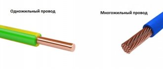
Copper ground bus
The copper-based grounding bus refers to conductors with low resistance values.
The standard element is fixed to the body of the electrical panel, and also easily withstands thermal loads and high voltage during a short circuit. One of the most popular options is a grounding copper strip, made using high-quality electrical copper of the “M-1” grade.
Copper grounding bar
The protective element is manufactured in accordance with GOST 434-78, and is characterized by a high level of alloy purity with a solid metal content of 99% or more.
Due to the high quality of the source material, the copper busbar is designed for operation in operating temperatures ranging from minus 55°C to plus 280°C, with a maximum operating voltage of 1000 W.
Established standards regulate the marking of copper grounding bars with mandatory indication of thickness, width and length.
Tire installation option
Copper grounding bars can be used not only indoors, but also outdoors, due to the following performance characteristics:
- high level of thermal conductivity;
- high level of electrical conductivity;
- low resistivity values;
- resistance to corrosive changes.
When installed externally, copper grounding bars provide effective lightning protection, so they are often mounted on lightning rods.
It is very important to install copper ground bars in regions where there is extremely frequent and high lightning activity.
Purpose
The use of a zero bus makes it possible to solve several very important problems:
First of all, you can create several points at once to connect loads from the common input to a zero-type conductor. Conduct visible grounding using a device with a cover made of transparent material that covers the terminals. Significantly improve the effective use of automatic protective devices. Ensure continuity of the circuit in the area from grounding to a specific load. Fulfill an important condition, which involves separating the wires of the neutral (protective) and working types. We talked about how to split a PEN conductor in a separate article.
Design features
First, let's look at the design of the comb. The product consists of a copper plate placed in plastic insulation that does not support combustion. Special leads extend from this plate, thanks to which the machines in the panel are connected. The number of plates corresponds to the number of poles.
Please note that there are combs with pitches of 18 and 27 mm. The first ones are intended for switching AVs with a width equal to one module. Accordingly, 27 mm is a width of 1.5 modules
Pay attention to this point when choosing a distribution bus for your own conditions!
Based on the number of poles, connecting busbars are divided into single-pole, two-pole, three-pole and four-pole. Each design option has its own purpose. For example, a single-pole comb is used to connect a single-phase circuit breaker, and a four-pole comb, respectively, is used to install three-phase RCDs with 4 poles (three phases and zero).
The number of taps can be from 12 to 60, so the use of combs to connect two electrical machines is not a rational solution. It is advisable to use a distribution bus when assembling large panels.
The taps themselves can be pin (marked pin) or fork (fork). The former are used much more often, because Fork outlets are not suitable for all machines; they require a special clamp.
The last design feature that I would like to talk about is the cross-section of the bends. As a rule, taps are made with a cross-section of 16 mm2, which is quite enough to withstand a current load of 63 A.
How to connect the phase and neutral wires
Connecting the phase conductor to the machine is mandatory. The neutral conductor does not always have to pass through the machine, but there are cases when it is recommended to use a two-pole automatic switch, and then both phase and neutral pass through it - each wire through its own section.
Simultaneous disconnection of phase and neutral is justified especially in situations where three-phase voltage is introduced into a house or non-residential building. In such situations, there is a greater risk that one of the phases may short circuit to zero. This is a short circuit mode to which the machine protecting this phase must respond. But in those fractions of a second while it is triggered, an overvoltage will occur in the other two phases. That is, instead of the required 220 V, there may be all 380 V - the voltage difference between the two phases with a conventional three-phase connection.
Not a single household appliance is designed for such voltage, and the more powerful it is, the more current it passes, and the greater the likelihood of it burning out due to overvoltage. Where the fuse of a low-power device immediately blows, powerful equipment will still “tolerate” a heavy load for some time, and during this time the switching power supply or transformer may fail. Therefore, it is preferable to protect equipment such as boilers, dishwashers and washing machines with two-pole circuit breakers that cut two circuits at once.
Keep in mind that phase imbalance is also harmful to the source that powers the building. A generator, a transformer booth, a substation - all this will deteriorate very soon. For such purposes, there are special three-phase circuit breakers, which, in the event of a large imbalance or failure in one of the phases, can immediately turn off all three phases simultaneously. For more critical circuits, it is recommended to connect a four-phase circuit breaker, which also de-energizes the neutral wire.
Metals used in tire production
Depending on the purpose and required operating parameters, the following can be used for the manufacture of conductors:
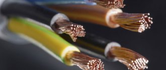
- copper;
- aluminum;
- steel;
- steel-aluminum - a steel core covered with a layer of aluminum wires.
The advantages of aluminum tires include anti-corrosion resistance, excellent electrical conductivity, low weight and reasonable cost. For their manufacture, low-alloy aluminum alloys with a low content of silicon and magnesium are used to improve the ductility and strength of the metal.
Copper buses with a copper content of up to 99% are in no way inferior to aluminum ones, but are less widespread due to their relatively high cost.
Zero bus
Zero tire on DIN rail
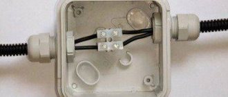
The connection of grounding and neutral working conductors is carried out using a zero bus. Its design consists of a conductive core and a plastic base, which is mounted on a DIN rail. The core is made of special electrical copper or brass. The design of the conductive element has holes and clamping bolts. Their presence allows for accurate and safe cabling in switchgear units. Models of zero busbars are made in different lengths, which allows you to make the required number of mounting holes in the core. Their main area of application is AC or DC networks designed for operating voltages up to 400V.
Thanks to the use of a zero bus it will be possible to:
- increase the efficiency of the automatic protective devices used;
- create simultaneously several points for connecting loads to the neutral conductor;
- carefully and safely separate neutral and working conductors;
- perform visible grounding using a plastic device with a cover to protect the terminals;
- install a single circuit from the grounding point to each load.
Installation of the zero bus is carried out directly inside the electrical panel or on a metal rail using a bolted connection. There are open and closed installation methods. The first option is provided for electrical cabinets with a closed structure, which prevents unauthorized persons from accessing the internal contents. Closed installation is optimal for networks to which expensive, energy-intensive equipment is connected - machines and mechanisms, power tools, etc.
Types of protection against electric shock
In accordance with paragraph 1.1 of GOST 12.1.030-81, protective grounding or grounding (zero-ground connection) is designed to protect people from electric shock in the event of insulation damage when they touch metal non-current-carrying parts of electrical equipment.
Grounding is an intentional or accidental electrical connection of metal parts of electrical equipment, electrical installations, or a network point to a grounding device, busbar or other protective equipment (clause 01-10-09 GOST R 57190-2016).
This could be reinforcement in the ground, building structures or special electrodes. This measure is a mandatory deliberate protection of both residential and non-residential assets.
Grounding is the deliberate connection of metal parts that are not energized in the normal state with a neutral protective conductor (solidly grounded neutral of a transformer or generator).
In accordance with paragraphs 1.1.2, 1.1.3, 1.7 of GOST 12.1.030-81, grounding must be done by electrically connecting metal parts of electrical equipment to a grounded point of the power supply using a neutral protective conductor (PE).
For neutral protective and grounding conductors, you can use: special conductors, as well as metal structures of buildings and structures.
Protective grounding and grounding of electrical equipment must be carried out without fail when using an alternating current voltage with a nominal value of 220 (1 phase) and 380V (3 phases) and higher and a direct current voltage of 440V and higher. In addition, according to clause 1.7.13 of the PUE, the power supply for electrical receivers must be supplied from a 380/220 V network with a TN-S or TN-CS grounding system.
Design features
Upon closer examination of the design, you will notice that it consists of a conductive core and a base made of plastic, which is designed for installation on a DIN rail.
The photo shows the appearance of the NS:
The current-carrying core contains holes and clamping bolts for fixing the conductors in it, as well as for neat and safe wiring of conductors N inside the switchgear. NS differ from each other in both the installation method (housing) and the number of mounting holes, respectively, in length.
To ensure a high-quality connection, as well as simplify further maintenance, the bus is made of a single conductive element of sufficient size made of electrical copper or brass. With a different number of bolt terminals to which neutral (N) conductors are connected.
A distinction is made between ground buses in a housing and grounding buses without a housing; the externally conductive elements are identical. The neutral bus is made in a housing or an insulator is installed. For the correct functioning of differential protection devices, it is necessary to connect them correctly, and to separate the conductors N from PE in the distribution board. In the case of a metal shield, this can only be done by isolating the neutral conductor from the housing.
Grounding device
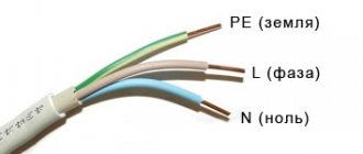
In many ways, the electrical circuit of the floor panel depends on the house itself. As a rule, in a private house, if there are no plans to connect such powerful devices as three-phase boilers, then a single-phase line is installed. These are two wires: zero and phase. In internal wiring, it is customary to wire the phase wire with a conductor in brown insulation, and the neutral wire with blue insulation.
If the wire is three-core, then the third wire is usually painted yellow with a green stripe. This bright conductor is used for grounding. It is never put into the machine inside the shield. The grounding conductor must be continuous, therefore, in switchgears, special conductive blocks are used, which are installed next to the machines in order to pass the grounding conductor through them and safely bring it to the floor where it is connected to the grounding bus. As a rule, this is either the first floor, or the basement, or the basement.
Installation Rules
Installation of the simplest terminal to the panel is carried out in a closed or open way. The first option prevents malicious damage to the bus of powerful or important devices, the second method is applicable if there is no risk of damage to the device. Zero blocks with screw connections are fixed to the distribution panel on a DIN rail; additional insulation for grounding is not provided.
The cross-section of neutral and phase conductors is the same. A similar requirement applies to tire parameters: the actual cross-section is considered to be the size of the thinnest sections. When combining a group of ground and neutral conductors, end consumers, after dividing the “PEN” input, are connected to different buses: PE and N.
Some tips for maintaining zero tires
Like any other power cabinet equipment, such a strip requires constant attention. After putting the switchboard into operation, after 1-2 weeks the connections should be tightened again. The fact is that the oxide film formed on the surface of the core will burn by this time, which will lead to a weakening of the connection.
This procedure must be repeated at least 2 times a year, as in the case of protective automation. It is necessary to ensure that dust does not accumulate on the zero bus. Ideally, it will be covered with a transparent plastic lid. You should sometimes check the strip visually - poor contact will reveal itself by darkening of the busbar or wire insulation near the connection.
Zero bus: types, what it is needed for
As is known, the power supply system for the end consumer is built according to the schemes recommended by the Electrical Installation Rules (PUE). A power cable is supplied to the facility, and further wiring occurs in the distribution panel.
For ease of installation and organization of power supply lines, inputs with different values are combined into contact groups.
A bus with a phase, a zero bus is a contact block in which there is the ability to reliably connect several conductors to power electrical installations.
Requirements for the zero bus
For a group network, the bus must be a single conductor, without the possibility of switching between its parts. The resistance should be the same along the entire length. Within one group line, it is allowed to combine conductors PE (protective grounding) and N (working zero). Moreover, after dividing the PEN input into PE and N buses, end consumers are connected to different buses. Important! Using one bus to connect the working zero and grounding is prohibited! This is a fundamental issue, it is necessary to understand the difference between separation and combination of PE and N. From the moment of separation, the ground and neutral lines can be laid in the same power cable, but the conductors must be insulated. Regardless of the connection method (three-phase or single-phase), the cross-section of the neutral conductor must correspond to the cross-section of any of the phase conductors. The same requirement applies to the cross-section of the tire itself. The cross-section of the connecting wires from the bus to the final electrical installation cannot be higher than the cross-section of the input power wire. If the bus is a structure with holes for connecting conductors, the actual cross-section is considered to be the geometric parameters in the thinnest part. There are no requirements for the mandatory production of a zero working tire from a specific metal
However, in practice, copper or brass is used. When calculating the cross-section of aluminum busbars in relation to copper busbars, a coefficient of 1.52 is applied.
For convenience, we will consider a single-phase circuit, which is used in most apartments in multi-storey buildings. Two main lines: phase and zero, are always present. They are inserted into the meter (electricity meter), and at the output they become available for further wiring. Depending on the system used, either only a zero bus or a zero and ground bus can be installed.
How to connect the phase and neutral wires
Connecting the phase conductor to the machine is mandatory. The neutral conductor does not always have to pass through the machine, but there are cases when it is recommended to use a two-pole automatic switch, and then both phase and neutral pass through it - each wire through its own section.
Simultaneous disconnection of phase and neutral is justified especially in situations where three-phase voltage is introduced into a house or non-residential building. In such situations, there is a greater risk that one of the phases may short circuit to zero. This is a short circuit mode to which the machine protecting this phase must respond. But in those fractions of a second while it is triggered, an overvoltage will occur in the other two phases. That is, instead of the required 220 V, there may be all 380 V - the voltage difference between the two phases with a conventional three-phase connection.
Not a single household appliance is designed for such voltage, and the more powerful it is, the more current it passes, and the greater the likelihood of it burning out due to overvoltage. Where the fuse of a low-power device immediately blows, powerful equipment will still “tolerate” a heavy load for some time, and during this time the switching power supply or transformer may fail. Therefore, it is preferable to protect equipment such as boilers, dishwashers and washing machines with two-pole circuit breakers that cut two circuits at once.
Keep in mind that phase imbalance is also harmful to the source that powers the building. A generator, a transformer booth, a substation - all this will deteriorate very soon. For such purposes, there are special three-phase circuit breakers, which, in the event of a large imbalance or failure in one of the phases, can immediately turn off all three phases simultaneously. For more critical circuits, it is recommended to connect a four-phase circuit breaker, which also de-energizes the neutral wire.
Benefits of using busbar trunking
An electrical bus is more convenient to use than a group of wires
The use of busbars in electrics instead of cable products provides significant savings in material, energy and labor resources:
- Installation takes 2 times less time than cable laying.
- Service life – up to 30 years without the need for complex maintenance.
- The flexible configuration allows for high-quality and safe installation of the network, depending on the route it runs.
- The busbar has a more aesthetic appearance than group wiring.
- Shielding the conductor eliminates the impact of the electromagnetic field on nearby office equipment.
- The design is fireproof and meets safety requirements for IP55 protection level.
More details about the appointment
Using a grounding zero bus in the wiring system allows you to solve many important issues:
- Creation of several points to share the total load from the main input to the neutral conductor.
- “Opening” the grounding mechanism through the use of a transparent cover in the design that protects the terminals.
- Increasing the efficiency and performance of automatic protection devices.
- Ensuring line continuity from direct grounding to the output point.
- Saving space in the panel, since there will be no need to place several single tires.
- Separation of neutral and phase wires.
In general, the zero bus allows you to raise the security of the network to a qualitatively new level, however, its use and connection must be as competent as possible, therefore special requirements are imposed on the installation of this element of the electrical network.
What is the difference between the zero and ground bus
The main thing is that after the RCD or RCBO they do not touch. Otherwise, there can be no question of correct operation. This action is called protective grounding. This cannot be called full-fledged grounding, but it copes with its task.
- There are many points to which the neutral wires can be connected.
- Providing easy access for maintenance when inspecting electrical power cabinets.
- Increasing the operating efficiency of protective automation elements due to the absence of heating.
Expert opinion
It-Technology, Electrical power and electronics specialist
Ask questions to the “Specialist for modernization of energy generation systems”
Zero bus in the panel - Everything about electricians in the house The closed installation option is used if the equipment is connected to particularly important systems, for example, to a power outlet of electrical installations. Ask, I'm in touch!
Characteristics
When choosing the necessary zero buses, it is worth presenting clear requirements for the design. The main thing is the cross-section of the wire. Guided by the clear rule “the cross-section of the wire does not exceed the cross-section of the main grounding bus,” you can provide high-quality power supply and save money on maintenance in the future.
The characteristics of the zero bus vary depending on the type of installation. There are two types of devices according to the distribution scheme that meets the requirements of the PUE:
In the first case, a grounded bus, which is a tightly grounded neutral, in which connection to the protective ground is provided exclusively at this point. Further, only two busbars are inserted into the shield along the insulated conductors. This scheme is considered the safest, since the neutral and grounding buses are separated directly at the entrance of the device into the room.
The second option presents an outdated but popular TN-C type circuit. In this case, the grounding is not represented by a separate conductor, but in the panel itself there is only a zero bus. Here, too, you cannot connect ground and zero. Therefore, here the concept of “earth” in its usual representation is not present.
Determination methods
Let's look at ways to determine the neutral and grounding conductors, from very simple to more complex.
The circuit has diff current protection
. If the entire object or branch under study is equipped with differential current protection - a differential current device or an RCD, the task is greatly simplified. You need to connect a control device, for example a lamp with conductors, to the phase and to one of the conductors being tested. If the differential protection does not work, then the lamp is connected to the working zero. If an RCD is triggered when a lamp is connected, you connect it to phase and ground. Everything is quite simple and at the same time check the residual current device in practice.
Before performing such a test, you need to make sure that the diff protection is working by pressing the “test” button on the protective device. It should be noted that the method will work provided that the current through the lamp exceeds the rated differential current of the device. That is, when using an incandescent lamp (an energy-saving lamp is not suitable), an RCD with a leakage current of 10-30 mA will trip. The introductory RCD for a 300 mA leak may not work; for a reliable test, you need to take a more powerful device.
Comparison with grounding contacts of sockets
. This method will work if there is a two-pole circuit breaker at the input that opens the working zero and there are grounded sockets in the room. The input machine should be turned off, thereby we will open any connection between zero and ground. If possible, unplug all appliances from electrical outlets.
Next, you should “ring” with a multimeter in resistance measurement mode the grounding contact of one of the sockets with the contacts being tested. When connected to the neutral wire, the multimeter should show a high resistance; with a ground contact at an unknown point with the ground of the socket, the resistance is almost zero.
In this way, you can at the same time check the correctness of the connected sockets: when the input two-pole circuit breaker is turned off, the neutral and ground contacts should not ring. Well, this is provided that the wiring is initially in good working order and installed correctly.
Climb into the shield
. If it is not possible to implement the previous methods, you will have to go into the “stuffing” of the electrical panel. I think there is no point in reminding about safety precautions here: no one has canceled it. In fact, the method is quite simple: you need to find the neutral conductor going into the room and disconnect it from the switchboard terminals. Then ring with the contacts being tested: the one with whom the call will be made is the neutral conductor.
In the case of a shield, difficulties may well arise when even in the shield it is difficult to distinguish zero from grounding. In this case, you will need current clamps. It is necessary to turn on the voltage and load in the room, and examine unknown conductors in the shield with clamps - where there will be current, there will be a working zero
Please note: the method only works if you know for sure that one of the conductors is zero and the other is ground.
All of the above methods work with both grounding and grounding.
Determine the contacts when connecting an electric stove
. Sometimes it becomes necessary to replace an electric stove socket, but the wiring is from Soviet times or the early 90s, one color. To correctly determine whether an electric stove is zero, a condition is necessary - a two-pole circuit breaker in the input switchboard, which disconnects both phase and zero from the entire apartment.
So, with the power turned on, we determine the phase on the terminals under study for the future socket - we mark this contact and throw it aside, then we don’t need it. Then you need to determine the zero in any socket in the apartment - since the wiring is Soviet, there is no ground there, so the zero will be the terminal on which the indicator screwdriver does not light up.
Now we turn off the power to the entire apartment and use a multimeter to dial the zero of a regular outlet with the two remaining contacts for the electric stove. The contact that rings with the zero of the socket is working, and the one that does not ring is zero (ground). If both contacts ring, you need to look for errors in the electrical wiring. When organizing grounding in Soviet times, it was connected to the “PEN” terminal without any switching devices.
Briefly about the design and operating principle
If you look closely at the photo of the zero bus, you can see a conductor made of electrical copper or brass on a plastic base. Each mini busbar is separated from its neighbor by a transparent plate, ensuring safety and insulation.
The holes and clamping bolts in the structure are designed to secure conductors and route them safely, and the device is fixed to a DIN rail using a plastic housing.
The length of the product depends on the number of mounting holes available, however, despite the difference in the clamping bolts, the tire is always monolithic, which simplifies maintenance and increases the safety and reliability of fastenings.
Also, grounding buses differ in the presence of the housing:
Zero tires with a body inside do not differ from their “bare” counterparts, but are externally enclosed in a special plastic block, which in most cases is made of opaque white plastic on three sides, and with a transparent bluish cover on the front side.
It is easy to identify this grounding device in the shield not only by its oblong shape, but also by the obligatory presence on the body or base of a blue or light blue color - a clear indicator of the zero type of the electrical network element.
Grounding device
In many ways, the electrical circuit of the floor panel depends on the house itself. As a rule, in a private house, if there are no plans to connect such powerful devices as three-phase boilers, then a single-phase line is installed. These are two wires: zero and phase. In internal wiring, it is customary to wire the phase wire with a conductor in brown insulation, and the neutral wire with blue insulation.
If the wire is three-core, then the third wire is usually painted yellow with a green stripe. This bright conductor is used for grounding. It is never put into the machine inside the shield. The grounding conductor must be continuous, therefore, in switchgears, special conductive blocks are used, which are installed next to the machines in order to pass the grounding conductor through them and safely bring it to the floor where it is connected to the grounding bus. As a rule, this is either the first floor, or the basement, or the basement.
Specifications
The grounding bus must be installed inside the electrical panel and connected to the current grounding circuit.
Due to its basic technical characteristics, such an element is used as a conductor between the grounding system and the plug part of the technical installation. Inside the input devices, as a rule, grounding buses of the “PE” type are used.
Ground bus with ground wires
In such conditions, the grounding conductor must have the appropriate cross-section:
- copper conductors - 1.1 cm or more;
- aluminum conductors - about 1.7 cm or more;
- steel conductors - 7.5 cm or more.
The cross-sectional parameters of the installed grounding bus must correspond to the parameters of the conductor.
| Tire type | Conductor cross-section | Current | Number of holes for fasteners | Number of clamps | Dimensions |
| RE 6/1 | 1.5-16 mm2 | 63 A | 1 | 6 | 6x9x46 mm |
| RE 8/1 | 1.5-16 mm2 | 63 A | 1 | 8 | 6x9x58 mm |
| RE 8/2 | 1.5-16 mm2 | 63 A | 2 | 8 | 6x9x64 mm |
| RE 10/2 | 1.5-16 mm2 | 63 A | 1 | 10 | 6x9x70 mm |
| RE 10/1 | 1.5-16 mm2 | 63 A | 2 | 10 | 6x9x76 mm |
| RE 12/1 | 1.5-16 mm2 | 63 A | 1 | 12 | 6x9x82 mm |
| RE 12/2 | 1.5-16 mm2 | 63 A | 2 | 12 | 6x9x89 mm |
| RE 14/1 | 1.5-16 mm2 | 63 A | 1 | 14 | 6x9x95 mm |
| RE 14/2 | 1.5-16 mm2 | 63 A | 2 | 14 | 6x9x102 mm |
| RE 16/1 | 1.5-16 mm2 | 63 A | 1 | 16 | 6x9x107 mm |
| RE 16/2 | 1.5-16 mm2 | 63 A | 2 | 16 | 6x9x114 mm |
| RE 18/1 | 1.5-16 mm2 | 63 A | 1 | 18 | 6x9x119 mm |
| RE 18/2 | 1.5-16 mm2 | 63 A | 2 | 18 | 6x9x126 mm |
| RE 20/1 | 1.5-16 mm2 | 63 A | 1 | 20 | 6x9x132 mm |
| RE 20/2 | 1.5-16 mm2 | 63 A | 2 | 20 | 6x9x138 mm |
| RE 24/2 | 1.5-16 mm2 | 63 A | 2 | 24 | 6x9x163 mm |
The grounding bus can be of the zero working type “N” and the protective type “PE”, but the installation of such a device must be carried out by specialists, which will make the operation not only durable, but also safe.
Installation Rules
Installation of the NS is possible both on a special rail and in an electrical panel. Installation options are available in both closed and open ways. The open method is perfect for a cabinet that will be closed to unauthorized persons. The closed version is used in situations where equipment is used that is connected to very important elements. An example is a power socket for various electrical tools.
The video below clearly shows how to install the NS on a DIN rail and how to fix it more reliably:
So we looked at the structure and purpose of the zero bus. We hope the information was useful and interesting for you!
You probably don't know:
- What is GZSh in electrical engineering?
- Why do you need a cross module?
- What is the danger of a broken neutral wire?
Dangerous defense option
Some would-be electricians decide to ground the apartment by simply connecting the third wire to the plumbing or heating system running through the room. Do not use this type of ground loop under any circumstances, because... in this case the picture is as follows:
- a breakdown of current occurs on the body of an electrical appliance (boiler or washing machine in the bathroom);
- dangerous current passes to batteries and hot/cold water risers not only of your apartment, but also of all neighbors, because the system is unified.
- Anyone who at the moment decides to drink water from the tap or simply touch metal pipes can become a victim.
By the way, the rules of the PUE stipulate this point and are also strictly prohibited, according to PUE 1.7.110 (see Chapter 1.7).
In addition to this method of grounding an apartment, the following are also considered unsafe:
- Connection in the socket of a neutral with a grounding conductor (the so-called grounding). If the neutral wire in the network suddenly breaks, dangerous voltage will transfer to the housing of all electrical appliances connected to the grounding of the apartment - computer, water heater, refrigerator, etc.
- Sequential grounding of electrical appliances (through each other). If you decide to make such a grounding loop, be aware that if an accident occurs, electromagnetic incompatibility may occur. As a result, electrical installations will create interference and there is a high likelihood that the ground loop will not prevent electric shock.
- Connecting several wires to one PE bus terminal. One conductor can be connected to each contact pad. Neglecting this rule is strictly prohibited.
Consideration of the issue by a specialist
That's all you need to know about how to make grounding in an apartment if there is none. We still strongly recommend using an RCD as a temporary protection option, and insist that the city authorities take care of upgrading the electrical wiring in your home.
Related materials:
- There is an electric shock in the bathroom - what to do?
- How to connect a voltage control relay
- Proper grounding in a private home
It is better to make two zero tires in the shield!
28 Jan 2022 Assembly of shields
Hello everyone, today is an article on practical experience in assembling electrical panels from experienced electrician Sergei Panagushin from Izhevsk. We will talk about such a nuance as installing zero busbars in the shield; Sergey will tell you how best to do it so that the contact of the busbar with the wires is the best.
If it’s not difficult for you, vote for this article by Sergei here - https://vk.com/wall-125051812_548
Just like it.
So, word from Sergei:
Hello dear reader! In today’s article I would like to share a couple of tricks that can be used when installing automatic machines and zero tires in the dashboard.
So: it is best to install tires not one at a time, but two at a time, as shown in the photo.
Why is this being done? Everything is very simple: with such an installation, the contact area increases and the connection is duplicated, and if under one screw the contact loosens, that is, the second contact and such a contact point will not heat up, which reduces the risk of failure of the electrical supply system.
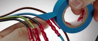
When installing busbars on circuit breakers, the insulated part can be wrapped with insulating tape instead of using end caps. This can be seen in the photo.
You don’t need to wrap a lot of insulating tape, just 1.5-2 turns is enough; if you do more, the busbar will not fit completely into the terminals of the machine, which can also have a detrimental effect on the operation of the electrical supply system. This is done in order to avoid causing an accident if work has to be done on the panel with partially relieved voltage.
PS I also sometimes use insulating tape as a tire heating indicator. For example, in the switchboard, we wrap insulating tape around the bus and periodically, when taking readings in the electrical switchboard, we look at the condition of the insulating tape
If it begins to shrink, then this indicates that there is heating in this place and you need to figure it out... Thank you for your attention!
Video from Sergei Panagushin:
Assembly of a 1-phase shield: Instead of an RCD, a difavtomat. 4 differentials for 4 groups.
Crazy hands: “comb” made of wire:
Crazy hands: Zero tire bulkhead:
In what cases is grounding necessary?
So why do you need grounding? For clarity, it is worth considering a few examples:
1. For example, there is a dishwasher in the apartment. But for some reason, at a certain moment, a phase appeared on the case, and the case was not grounded. But the neutral of the power line, which leads to the house and provides electricity, is grounded, and taps and batteries are also grounded.
If you are wearing rubber slippers, then upon contact there will be no unpleasant sensations or even the slightest blow. But if there are no shoes, and at the same time the person also grabbed the tap, and the second hand is located on the body, then it becomes a conductor of electric current, which is supplied through the body to the person, and then into the ground to the neutral, and to the substation.
2. If the dishwasher is grounded? What will happen in such a situation? If for some reason a zero appears on the housing, the current will immediately go into the ground. Even if the person is barefoot, even if he is wearing slippers, nothing will happen, the grounding has worked, there is no electric shock, everyone is safe and sound. One downside, the dishwasher will need to be repaired, but it will still be cheaper and better.
3. The washing machine in the room has broken down, and the equipment body is under voltage. In this case, if the person comes into contact with the body, he will receive an electric shock. This is why grounding is needed, then the current goes into the ground and everything is fine with the person.
The fact is that the resistance of human skin is much higher than the resistance of the wire, and then the current follows the path of least resistance, enters the ground, and the person remains intact. This is one of the simplest examples, which shows why grounding is needed in a house or other building. Without such a system, the risk of receiving an electric shock increases.
Expert opinion Evgeniy Popov Electrician, repairman
It is worth taking one more point into account, especially for the owner of a private house this is extremely important information. Even if the structure is built from natural material, the amount of electrical wiring remains the same as in a multi-story residential building, but the natural material is highly flammable. It is on this basis that a grounding system in a private home can prevent the occurrence of unpleasant situations and harmful consequences.
The most terrible event that can happen is a fire; it occurs due to a short circuit or failure of electrical equipment. That is, if doubts and questions arise about why grounding is needed in a private home, you need to realize that such a system protects not only from fires, but also prevents each family member from electric shock.
Expert opinion Evgeniy Popov Electrician, repairman
The situations can be quite scary, but they are a clear example of what negligence and disregard for safety precautions can lead to. As you can see, sometimes the consequences can really be the most serious and harmful.
Installation
There are several ways to organize the installation of a grounding bus, but the most popular are installation in an electrical panel and outside the cabinet.
Panel mounting
Cabinets with an installed bus can be placed on the facade of the household or in a special, separate panel room. For outdoor or outdoor installations, shields are suitable, the body of which is marked with the IP index. Installation of a grounding device involves the following activities:
- fixing the main grounding bus with a bolted connection on the body of the steel shield;
- connecting the protective element to the zero rail using a jumper made of steel or copper;
- The dimensions of the installed element must be comparable to the cross-sectional indicators of the “protection” and “zero” conductors.
Grounding diagram
It should be noted that the rules for placing the grounding bus and other elements inside the electrical panel are not specified in regulatory documents.
The PE copper grounding plate installed inside the shield must have a minimum cross-section of 10 mm2, and the steel one - at least 75 mm2.
Installation outside the panel
External installation of the grounding bar is carried out in areas that have sufficient protection from unauthorized access by unauthorized persons. Fixation is carried out with durable insulators.
Assembly and installation of electrical panels. Cable connection diagram
The most convenient options for external arrangement of the grounding bus include the use of special DIN rails.
A fairly common method used to connect individual elements of the grounding bus is welding, which fully complies with all GOST requirements for arranging reliable and safe contacts.
Secrets and standards of installation
When installing the zero bus, one of several possible types of installation can be used (the appropriate one is prescribed in the instructions):
- On an insulator, screwed in the center or along the edges;
- Screw;
- On DIN rail;
- On G-rail.
In turn, zero bus insulators can be absent or can be case-type, “rack” type, combined, single or double corner (“leg” type).
- Familiarize yourself with the appropriate panel connection diagram, find the zero bus in the image (the icon repeats the general appearance of the device marked “N”).
- De-energize the electrical panel by unscrewing all existing plugs or placing the circuit breakers in the inoperative position.
- Check that there is no voltage by holding an indicator screwdriver or multimeter to the input conductors.
- Determine the location for placing the bus depending on its design features (if fixation to special strips is provided, then install the necessary ones in the panel; if not, fasten them through insulators to a free place).
- Install the strip on the DIN or G using special clamps, or directly into the panel using a screw type of installation from the center or sides (where the insulator is located).
- Check the reliability of the fastenings by trying to “loose” the installed structure.
- Connect the conductor coming from the residual current device to one of the busbar clamping bolts.
- If the circuit has two or more protective connection devices, then each of them is connected in series to the bus.
- Connect the neutral conductors coming from the circuit breakers of each branch of the network to the corresponding terminal of the neutral protective device.
- Connect the common “zero” of the network to the outer terminal on the zero bus.
- Check the correctness and quality of all connections made.
- Turn on the electricity supply.
During work, it is important to follow the safety rules:
- Install only when there is no current in the conductors;
- Use special clamps, terminals, and not homemade “twists”;
- Ensure good contact of the wires, if necessary, trim and strip their ends;
- Do not allow wires to overlap, twist, break or bend;
- Do not neglect marking conductors in any available way (color, signature, signs).
The zero line is an integral part of any electrical network, so it is important to properly organize its functioning inside the panel. The zero bus will provide order and the possibility of sequential connection of all contacts to ensure safe, comfortable and complete use of electricity.
Electrical busbar markings
Marking of zero tires
The application of color markings to electrical busbars is regulated by current standards. Compliance with their requirements is mandatory for every manufacturer. Marking can be applied both at the production stage and after its completion. In the first case, colored insulation is used, in the second, colored insulating tape is used, indicating different phases of the conductor.
The color designation of tires allows you to accurately determine their type and purpose:
- The grounding conductor is marked in yellow and green in the form of alternating longitudinal stripes.
- Neutral and working conductors are indicated using blue color.
- Connecting conductors involves using all three shades in different versions: insulation with longitudinal yellow and green stripes and a blue line at the end, or blue insulation with a yellow-green stripe at the joints and at the ends of the conductor.
According to the requirements of current standards, along with the color marking of conductors for alternating current networks, the following letter designation of conductors is used:
- in a single-phase network – L;
- in a three-phase network - L with numbers from 1 to 3;
- medium – M;
- neutral, or zero – N;
- grounding – PE;
- combined working and neutral - PEN (combination of the designations of each of the conductors used).
Models for DC networks are marked with the letter L with a + or - sign, respectively - a positive or negative conductor.
Assembling an electrical metering panel with an RCD
connecting the input cable SIP 4x16
First of all, we connect all the large-section wires. In our case, these are Self-Supporting Insulated Wires (SIP). Only four pieces. They are all aluminum, with black insulation on the outside. Their markings are made in the form of a continuous colored stripe.
We connect the yellow, green and red conductors to the upper terminals of the input AB - these are three phases. PEN – with a blue stripe, to the zero terminal of the electric energy meter.
Usually these are the two on the far right. You can connect to any of them, they are internally connected.
Earthlings
Next, we connect the grounding conductors to the distribution block. First of all, as the largest, from the circuit mounted on the site. There is also grounding of the current-conducting body of the shield, which is mounted under a special bolt.
It is this connection scheme of N and PE that distinguishes the TT system from others.
In the TN-CS system, the metering board diagram with an RCD, which we have already reviewed HERE, everything is done differently. There, on the contrary, both the PEN conductor and the grounding loop of the house are combined in the distribution block. And only after that they share.
Here, the input SIP with a blue stripe - PEN, is essentially the working zero “N” of the entire electrical installation. The protective zero, also known as “PE” grounding, is taken from a circuit mounted in the yard.
How to connect several machines
The choice of circuit is determined by the characteristics of a particular electrical network. The easiest way is to install one RCD immediately after the meter. A safer option is to connect protective devices on individual lines. If one device fails, the others will remain in working order. The implementation of the second scheme requires the use of a marker panel.
Simple scheme
Using an example, it is convenient to consider a single-phase circuit used for most apartments in multi-storey buildings. A two-pole circuit breaker is installed at the input, connecting the RCD. Bus “0” in the electrical panel is marked “N”. A two-pole residual current device is connected to two single-pole circuit breakers. The output of individual machines allows you to connect loads in parallel.
The phase connected to the circuit breaker enters the input of the RCD with output to the switches. The zero output from the machine is sent to the corresponding bus, then to the input of the connected device. The neutral wire coming out of the consumer equipment is directed to the second neutral terminal. The presence of an additional bus “0” allows the RCD to control the incoming and outgoing voltage.
If two RCDs are connected, three brass blocks will be required: the main zero bus marked N1 and bars N2, N3 for residual current devices. The RCD is grounded to an additional element of the electrical panel - bus “P”.