The need to determine phase, zero and grounding arises when installing sockets to which unmarked conductors are suitable. Therefore, before installing an outlet, it is worth finding out what each specific wire is responsible for.
After reading this article, you can learn how to determine zero, phase and ground in a network using a screwdriver, multimeter or improvised means.
Using an indicator screwdriver
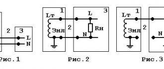
Two-wire network
Residents of old houses will have to deal with such wiring. This option is designated as TN-C and its essence is that the neutral wire, which is grounded at the substation, is also grounding. That is, in a two-wire network you simply will not find a grounding conductor, since its functions are performed by zero. The phase with zero is determined simply: attach the indicator to each of the wires, if there is contact with the phase, the indicator lamp will light up.
It is worth noting that this wiring option is outdated, since all plugs of new electrical appliances have three terminals.
Methods for determining zero, phase and grounding may differ depending on the system of conductors that run in the room.
Three-wire network
This type of network involves introducing three conductors into an apartment or house. The three-wire network is divided into several types. If you disassemble the TN-S system, then the protective grounding and zero are removed from the supply substation separately.
The purpose of the wires in this type of electrical network can be found out in this way:
- determine the phase in the distribution box or panel using an indicator;
- the remaining ones are zero and protective ground. It is worth disconnecting one of the wires from the shield;
- If you turn off the working zero, then all electrical appliances in the room will turn off. Using the method of exclusion, we obtain the definition of the third conductor, which performs the functions of protective grounding.
Now it’s worth finding out the phase, neutral and ground in the socket (if they are not indicated by different colors of the winding). Take the socket into which the lamp is screwed in and the wires are brought out, and touch one of them to the phase that you have already found with the indicator. With the second wire coming out of the cartridge, touch the two remaining wires in turn. If the zero on the panel is not turned on, the lamp will light up only when it touches the ground.
When handling TN-CS type wiring, protective grounding and zero diverge not from the substation, but when the conductors are introduced into the room. In this case, you should be guided by the plan that was described to determine the purpose of the TN-S system wires. Also, by examining the place where the PEN is separated, you can distinguish the working zero from the ground by the cross-section of the core.
When grounding is carried out by the TT system, the house is equipped with its own grounding device, from which protection is wired. In this case, zero, phase and ground are determined by finding the ground wire along the laying route.
Transformer substation
Transformer substations are electrical installations designed to receive, convert and distribute electricity from power lines.
Substations consist of a step-down transformer, switchgear (RU) and control devices.
Based on the method of construction and location, substations are divided into attached, built-in, and in-house. For suburban areas, mast and pole substations are the most common.
The main element of the substation is the step-down transformer. Step-down transformers can be three-phase or single-phase. Single-phase transformers are used in combination with three-phase transformers and mainly in rural areas.
The voltage in the transformers is reduced to a rated operating voltage of 380 or 220 volts. These voltages are called linear and phase, respectively. And the power supply to consumers is called three-phase and single-phase, respectively. Let us consider the types of consumer nutrition in more detail.
Using a tester or multimeter
Using a multimeter, you can try to determine the voltage passing between the conductor and the water supply or heating pipes. However, there will not be a 100% correct result. Often, the voltage between the phase and the water supply or heating system is equal to 220 V (in any case, the voltage should be higher than its value between the heating pipe and zero). But your measurements can be disrupted, for example, by a neighbor who “rewinds” electricity by choosing a heating pipe as grounding.
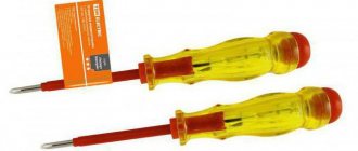
Of course, the best device for determining the phase is a screwdriver, which is combined with an indicator. I would like to believe that any owner who has a multimeter probably also has an indicator.
If you use a multimeter to determine the assignment of the conductors in a three-wire phase, it can show the voltage between the phase and one of the two remaining wires. Having thus learned the phase, you can use the above method and determine the protective zero and the working zero. We are talking about disconnecting one of the zeros and determining their purpose using a lamp in the socket.
Why not 4, 5 or more phases?
Here the answer lies in economic feasibility. In Russia, the overwhelming amount of electricity is spent on operating three-phase motors. To create a rotating electromagnetic field, a minimum of 3 phases are required, each of which is shifted relative to the other by 120° (see figure below). If there are three phases, the motor will operate normally and stably.
In theory, you can connect 4 phases, which, by the way, will allow the engine to run more smoothly. But for the operation of the fourth phase, it will be necessary to lay additional wire, which on a national scale amounts to millions of tons of non-ferrous metal, additional insulators, reinforced supports, etc. All this incurs enormous costs, which in fact are not justified. So in this case, three phases are the “golden mean”.
So, three phases are REQUIRED to run three phase motors, but four, five or more are a waste of money.
Interesting things from the world of electrical engineering:
- Why is there 220 V between phase and zero, and 380 V between phases?
- How Europeans make money from solar energy: real experience
Other things to consider
By studying the markings of current-carrying conductors, you can make it easier for yourself to find out their purpose:
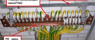
- The land is marked with the Latin letters PE. When combining the functions of the working and protective zero, the PEN marking follows. Yellow insulation is used, with one or two green stripes;
- zero is designated as N, its insulation is made in blue or light blue. Also sometimes found with a white stripe on a blue background;
- The phase marking is the Latin letter L. In the case of a three-phase network, the designation will be the letters A, B or C. The insulation is made in any color except those listed above. In practice, in all cases, the color is black, red or brown.
Often, determining phase, neutral and ground using a screwdriver or tester is a last resort, since most wires are marked with different colors or letters.
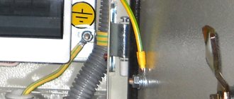
If you are familiar with the rules for installing electrical wiring, then determining phase, zero and ground will not be a problem for you. The phase comes into the fuse panel or electrical switch. The zero is mounted on a bus, which is equipped with several terminals. Also, in old shields and terminal boxes, ground and neutral were mounted with a bolt under a nut, which was welded to the box body.
Visual inspection and phase determination
So, the most reliable way to determine which specific wire has a phase is the color of the insulation. The phase is usually connected to either the brown or black wire. This is a well-known rule of the PUE, which every electrician must unquestioningly follow.
Color coding of wires is a very important norm in electrical engineering. It is simply unacceptable to throw a phase on the blue wire, since the blue marking is only for the working zero. Below is a table of color markings for electrical wires.
As can be seen from the table, the phase is always either brown, black, or red wires. The working zero is connected to the wire with blue or blue insulation, and the grounding system is connected to the yellow-green or green conductor.
Useful tips and general recommendations
Working with electrical wiring requires care and caution.
Electricians advise:
- Do not rely entirely on the color differentiation of wires or their markings; check the contacts with testers again. Cases of violation of electrical installation standards are not uncommon.
- If possible, avoid determining the voltage in conductors using a “tester” or a potato. Such methods are considered extreme, and it is better not to abuse them without experience.
- When using a multimeter, read the instructions in detail before use. Pay attention to the device settings.
Installing wiring according to standards will facilitate further connection of receivers and extend the service life of the entire electrical network. In addition, compliance with the necessary installation standards will make electricity consumption comfortable and safe.
Source
Is it worth looking for the phase with a light bulb?
Some electricians prefer to look for a phase with a test light. To do this, they take a regular incandescent lamp, a socket and two stranded wires. The wires are connected to the socket, and the light bulb is screwed into it accordingly. Then one end of the wire touches the metal heating pipe, and the second is inserted into the contact to search for the phase. Where the light bulb lights up, there is a phase.
We do not recommend this method, as it is fraught with electric shock - if you move carelessly, you can touch the bare wire. There have also been cases when an incandescent lamp exploded the moment it touched a phase. For these reasons, it is better to refrain from such a “folk” method of determining the phase and use specialized instruments.
Source
Finding the phase with a multimeter
If you don’t already have a multimeter, we recommend that you learn how to choose a good device from this article. To determine the phase conductor with a multimeter, it is important to perform the following steps:
- We switch the regulator to the AC voltage measurement mode (as shown in the picture). Please note that measurements can be made in the range from 1 to 200 V and from 1 to 750 V. We select the second mode, since our network has 220 V
- We insert one of the probes into the contact, and press the second one with two fingers - the voltage reading should be displayed on the device
- If up to 10 - 15 V is displayed, most likely you have hit the neutral wire. If the voltage is from 100 to 230 V, this is a phase
- You can also not pinch the probe with your fingers, but touch it to the wall next to the outlet or to a grounded metal surface
Even the most inexpensive device is suitable for such measurements. For example, DT 830B, which we use ourselves. It costs only 250 rubles, but its measurement accuracy is good.
Why do you need to know where the phase is?
Determining the phase conductor is necessary in the following cases:
- Installation of switches
. Light switches only open the phase. If you mix it up and put a zero on the switch, then the socket will always be energized and replacing light bulbs or repairing the socket can be dangerous to human life. - Installation of automatic machines
. Typically, single-contact circuit breakers are used, and only the phase enters them. Zero remains unconnected. Therefore, in order not to confuse and set a zero on the machine, it is necessary to clearly identify the phase wire.
Additional information about finding the ground, phase, neutral wire
We remind you that we considered cases when there is no indicator screwdriver at hand, but there are current clamps and a multimeter. Then, before entering the apartment, they detect the ground, phase, neutral wire, and the home network is dialed. There are three cores, the technique is on the surface: between the phase and the other wire, the potential difference will be 230 volts. Please note that the technique is not suitable in other cases. For example, the voltage difference between two identical phase conductors is zero. It is difficult to measure and determine with a tester.
Let's add another method - it is prohibited by industry. A light bulb in a socket with two exposed wires. Using the tool, they find the phase; it is possible to short the core to ground. You cannot use water, gas, sewer pipes or other engineering structures. According to the rules, the cable antenna braid is equipped with grounding (grounding). In relation to it, it is permissible to use a tester (a light bulb in a socket prohibited by standards) to find the phase.
For determined people, we recommend fire escapes and steel tires for lightning rods. You need to clean the metal until it shines, call the phase phase. Please note that not all fire escapes are grounded (although they must be), lightning rod buses are 100%. If you discover such blatant arbitrariness, contact the management organizations; if there is no response, inform the government authorities. Indicate a violation of the rules for protective grounding of buildings.
Potatoes are not only food
If you don’t have any equipment at hand, there is one popular method: using potatoes. Those who have used this simple method share their experience:
- You will need large raw potatoes;
- Resistor (with a nominal value of at least 1MΩ);
- Two wires.
The first wire is stuck at one end into the potato, the other end is connected to the metal (to heating or water supply). The second wire is stuck into the cut of the vegetable at a great distance from the first, and the other end touches the wire being tested through a resistor. After this, you should wait a few minutes; if a reaction appears, then this is a phase.
To determine phase or zero, you can use any of the listed methods - the main thing is to always be careful when working with current and follow safety rules (it is recommended to use protective rubber gloves when working).