How is a phase indicated in electricity?
Definition 1
A phase is popularly called a wire carrying electric current.
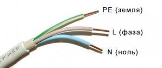
If you are dealing with a wire in which there is only one conductor - a phase, that is, current-carrying, then the Latin letter $L$ will be used in the diagram to designate the phase.
If you have to deal with all three phases (for example, if for some reason you had to climb into a panel in the entrance), then all three phases will be designated by the letters $L1$, $L2$, $L3$, respectively.
Also, for a three-phase power supply system, the letters $A$, $B$, $C$ can be used to designate all three phase conductors, but according to GOST 2.709-89 for Russia, the more desirable designations for phase conductors are the designations $L1$, $L2$, $L3$.
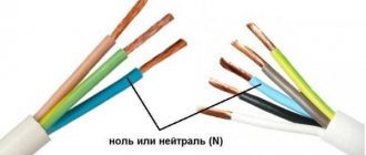
A three-phase circuit with three wires is called three-wire, while a three-phase circuit with four wires, one of which is neutral and the rest are phase, is called four-wire.
Why you can’t separate the PEN conductor in the floor panel
This option cannot be used for a number of reasons:
- If we take into account exclusively the provisions of the PUE, they state that the separation of wires should occur at the input circuit breaker of an apartment building or a private detached house.
- Even if the apartment panel is considered a water machine (which is quite problematic to do), such a connection will be incorrect according to another requirement, namely, the PE conductor must be re-grounded, which is impossible to achieve in the floor panel.
- Even if you get clever and connect the grounding to the floor panel, there is another obstacle that threatens with large fines. The fact is that the electrical circuit during the construction of a house is approved by several authorities and its unauthorized change is a gross violation of all existing rules - in fact, it is a change in the design according to which the house was connected to the network. Such matters should be handled exclusively by the organization serving this house or area.
Of course, if such an organization plans any work to separate the Pen conductor, then there is no point in messing around with each floor panel separately. The best option would be to separate it at the input machine, which is what will be done.
An additional argument in favor of separating the Pen conductor on one circuit breaker in a residential building is the requirement of the PUE (clause 7.1.87) to install a potential equalization system in this place.
Requirements for wiring colors during installation
A copper wire with one or two cores is pulled from the distribution box to the switch. The number of cores depends on the number of keys on the device. The phase should be broken, not the zero. During operation, it is allowed to use a white conductor for power supply, making a mark on the diagram.
The socket is connected taking into account the polarity. The working zero will be on the left, the phase will be on the right side. Grounding is located in the middle of the device and is clamped with a terminal.
If you have two cables of the same color, you can find the phase and neutral using a tester, an indicator screwdriver, or a multimeter.
On the electrical diagram it is worth indicating what L and N mean, but there are several of them used in electrical engineering. The single-line display shows the power part - type of power supply, number of phases per consumer. Here it is advisable to draw one notch on a single-phase network, three on a three-phase network and indicate the wires in color. Switching and protective equipment is marked with special symbols.
Correct marking and color marking of wires ensures the quality of installation and maintenance of the line. Labeling in accordance with international requirements allows electricians and home craftsmen to navigate the circuit.
PE conductor - what is it and what is it for?
The TN-C grounding system, despite the fact that it is still used in most apartment buildings, is outdated and is being actively replaced by TN-S or TN-CS, which are more advanced in terms of protection. As a result, in electrical circuit diagrams N is used as the working zero, and the PE conductor is the protective zero that appears in the circuit after the PEN wire is separated, or taken directly from the ground loop.
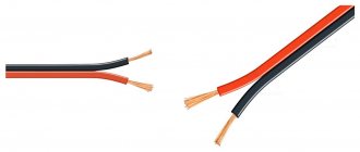
Conductor insulation coating colors
It is necessary to color-code grounding, phase and neutral cables in accordance with the requirements of the PUE. The document establishes color differences for grounding in the electrical panel, as well as for zero and phase. Understanding the insulation color code eliminates the need to decipher letter markers.
Ground wire color
In the Russian Federation, the European standard IEC 60446:2007 has been in force since January 1, 2011. It notes that the grounding has only yellow-green insulation. If an electrical circuit is drawn up, the ground should be designated as PE.
What is the neutral wire for? What is a neutral wire
Novice electricians often have a question: “Which wire is the neutral wire in the home power supply system?” To answer this question, you should know that the neutral wire is necessary to avoid “phase imbalance”. Experts strive to achieve a uniform load when supplying electricity to consumers.
To clearly explain this phenomenon, let’s take as an example an apartment building, where an equal number of apartments are connected to one of three phases. However, uneven consumption in this case still remains. After all, people in each apartment use different electrical appliances at different times of the day and night.
The principle of operation of the neutral wire
Electricity comes to consumers from a voltage transformer, which is capable of converting the voltage of an industrial network into the secondary winding of the transformer is connected in a star circuit, i.e. three wires are connected at one zero point. The second end of the high-voltage wires is connected to terminals called A, B and C.
The ends connected together at the zero point are connected to the ground loop in the substation. There, the high-voltage wire of zero resistance is also divided into:
- protective PE conductor (painted yellow-green);
- working zero (colored blue).
According to the scheme described above, it works in new buildings. It is called the TN-S system. In the building's switchboard, electricians supply 3 phases, a PE conductor, and a neutral wire.
Most old apartment buildings do not have a PE conductor. The power supply system consists of 4 wires, it is called TN-C. It is outdated and considered unsafe. In this case, the neutral wire is grounded at home.
The phases and zero from the voltage transformer are carried to residential premises by underground or above-ground high-voltage wires, subsequently connecting them to the input panel of the house. This creates a three-phase system with a voltage of 380/220 volts.
From the input panel, electricians route wires to entrances and apartments. Electricity is supplied to consumers using wires connected to one of three phases with a network voltage of 220 volts.
Also, a PE protective wire (only when using the new TN-S system) and a neutral wire are installed in the living space.
When zero-resistance wires are connected to each electricity consumer, the uneven load on the electrical network practically disappears.
Why is PE protective conductor needed?
A protective conductor or PE is necessary for additional protection of the home. In the event of a short circuit, it diverts current from the location where the wiring is damaged, thereby protecting people from electric shock and property from fire.
In such a network, the load is distributed evenly, since each floor of an apartment building is wired in phases.
Advice
The electrical system connected to residential premises is a “star”, which repeats all the vector characteristics of the transformer substation.
Such a system is reliable and optimal, but it also has its drawbacks, since malfunctions periodically occur. Most often, power outages are associated with poor quality wires, as well as poor-quality connections.
Causes of breakage in zero and phases
If there is poor contact between the wires and increased loads on the power supply system, the network breaks.
If any of the three conductors powering the house breaks, consumers connected to it will not receive electricity. At the same time, other consumers who are connected to the remaining two phases receive electricity in full. The current in the neutral wire is summed up from the phases remaining in working condition and will be equal to this value.
All breaks in the network are associated with a power outage to the apartments. Such accidents cannot damage electrical appliances.
Dangerous situations that threaten indoor fire and equipment breakdown occur if the connection between the voltage transformer at the substation and the distribution panel is broken.
This situation occurs due to many factors, but the most likely cause of power outages is due to an error by the electrician crew.
Causes of short circuit
A short circuit becomes possible when the current does not pass through “zero” to the ground loop A0, B0 and C0. Instead, the currents move along the external circuits AB, BC and CA, which are powered by a voltage of 360 volts.
Thus, on one panel of the apartment there may be too little voltage, since the frugal tenant has turned off all electrical appliances, and on the other, a voltage close to linear is formed - 360 volts. This causes damage to the wires.
note
The devices, in turn, overheat as a result of the supply of off-design currents to them.
To avoid such a situation and protect against a sudden surge in voltage, there are protection devices that are installed inside apartment panels. They are also placed in the housing of expensive electrical appliances to prevent breakdowns, for example, in refrigerators and freezers.
Method for determining zero and phase in a house
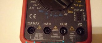
To identify a fault in the electrical wiring at home, most often they use a budget screwdriver with a light indicator. Such a device works due to the passage of capacitive current inside its body. The internal part of such a device is equipped with the following components:
- a bare metal tip, which serves to connect it to a phase or neutral conductor;
- a resistor that reduces the amplitude of the current passing through the screwdriver to a safe value;
- a light indicator that lights up when current flows through the metal part of the device. A burning indicator indicates the presence of current in the phase;
- a platform through which current passes through the human body and reaches ground potential.
Marking
There is not only the color of the wires phase, zero, ground, but also other types of markings, primarily alphabetic and digital designations. The first letter A indicates the wire material - aluminum. If this letter is missing, the core material will be copper.
Basic marking of wires in electrical engineering:
- AA - corresponds to a multi-core aluminum cable with an additional braid of the same material.
- AC – additional lead braiding.
- B – the presence of protection from moisture and additional braiding made of two-layer steel.
- BN – non-flammable cable braid.
- G – absence of a protective shell.
- R – rubber shell.
- NR – rubber shell made of non-flammable material.
Ground wire color
From 01/01/2011 the color of the grounding (or grounding) conductor can only be yellow-green. This color marking of wires is also observed when drawing up diagrams on which such conductors are signed with the Latin letters PE. The coloring of one of the conductors on cables is not always intended for grounding - usually it is done if there are three, five or more conductors in the cable.
PEN wires with combined “ground” and “zero” deserve special attention. Connections of this type are still often found in old buildings, in which the electrification was carried out according to outdated standards and has not yet been updated. If the cable was laid according to the rules, then blue insulation was used, and yellow-green cambrics were put on the ends and joints. Although, you can also find the color of the grounding (grounding) wire exactly the opposite - yellow-green with blue tips.
Protective grounding is mandatory when laying lines in residential and industrial premises and is regulated by PUE standards and GOST 18714-81. The neutral grounding wire should have as little resistance as possible, the same applies to the grounding loop. If all installation work is carried out correctly, then grounding will be a reliable protector of human life and health in the event of a fault in the power line. As a result, correctly marking cables for grounding is critical, and grounding should not be used at all. In all new houses, wiring is done according to the new rules, and old ones are put in line for replacement.