Regardless of what type of protective equipment is used in a building, it is always designed to handle a certain level of current, above which the power supply will shut off. To understand what kind of equipment you need to select, or to analyze whether the installed devices comply with the norm, it is worth determining the current strength during a short circuit. Finding it is quite simple - to do this, you need to divide the rated voltage in the circuit by the total resistance in the circuit between phase and zero.
Accordingly, it is necessary to find the last indicator using the test method. Measurement of phase-to-zero resistance , which is required specifically to verify the correct use of protective equipment, is carried out annually, or once every 6 months if the installation has a high-risk status.
How to measure phase-zero resistance?
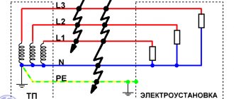
The measurement technique is not very difficult if the installation has already been put into operation. To do this, the contacts of a standard ohmmeter are connected to the phase and zero lines in the shield. If we are talking about sequential testing of several separate installations powered from one switchboard, then you need to connect the device leads to the most distant point from the switchboard. Electrical tests are carried out according to the standard scheme - voltage is passed through the circuit, and the device measures its drop, as a result of which the impedance indicator is calculated. The research diagram for installations with grounding and protective grounding is presented in the following figure:
However, if measuring the insulation resistance of electrical wiring can be carried out even when the installation is not yet ready for operation, in this case this is impossible. Therefore, when designing a system, the circuit resistance between phase and zero is determined by calculation. To do this, you need to add up the indicators of the current-carrying wires, the neutral of the transformer and its winding, the contacts of automatic protective devices, as well as the starters used in the equipment. The total value can be used to calculate the short circuit current.
Standard levels of indicators for measuring phase-zero resistance
It’s worth pointing out right away that the circuit resistance between phase and zero is not standardized - there are only standards for short-circuit current. It must be three times the rated response level of the protective devices - regardless of whether they are represented by automatic releases or fuses.
Based on this, the performance of the security system should be analyzed. If the circuit current is less than the nominal value, it is worth replacing the circuit breakers and fuses. If it significantly exceeds three times their nominal value, it is necessary to check whether the protective devices are selected correctly - a serious excess can lead to rapid breakdown of the equipment.
Below you can use the online calculator to calculate the cost of electrical laboratory services.
Regardless of what type of protective equipment is used in a building, it is always designed to handle a certain level of current, above which the power supply will shut off. To understand what kind of equipment you need to select, or to analyze whether the installed devices comply with the norm, it is worth determining the current strength during a short circuit. Finding it is quite simple - to do this, you need to divide the rated voltage in the circuit by the total resistance in the circuit between phase and zero.
What is a phase in electricity - definition of the concept
Phase in electricity is the colloquial name for a wire that is energized relative to another, which is called zero. This name comes from the fact that the current generated at substations and supplied to houses is variable, that is, the EMF created at substations have the same frequency (for Russia and the CIS countries it is 50 Hz), but are shifted relative to each other friend in time at a certain phase angle. Houses are usually supplied with all three phases and it does not matter which phase your apartment is connected to.
Figure 1. Electrics and electricity - schematic representation of phase, zero and ground
In Fig. 1 is a schematic diagram of the flow of electric current into the apartment from the general system. The letters $L1$, $L2$, $L3$ denote phases 1-3, and the letter $N$ denotes the neutral wire.
In Fig. Figure 2 shows a schematic connection of current to the apartment from the transformer, the letter $L_T$ denotes the phase on the transformer, the letter $L$ denotes the phase in the apartment, and the letter $R_H$ denotes a connected electrical appliance that has some resistance $R_H$.
There are 2 wires coming from the transformer, one is the so-called phase wire with voltage, and the other is the neutral wire, from which the grounding is carried out by placing the contact in the ground. There are other sources of grounding besides the ground itself; in these figures, grounding is indicated by the letters $Zml$.
In Fig. Figure 3 shows the case when the neutral grounded wire is not routed into the apartment from the substation, but is grounded directly in the apartment. The voltage $L_T$ between zero and phase will be the same for Figures 2 and 3, however, it is not recommended to ground the voltage from the transformer directly in the apartment.
How to assess the condition of the grounding loop in an apartment?
To measure grounding resistance, a tester or a test lamp structure is used. You will also need a screwdriver and an insulated wire with two probes. If you have a multimeter handy, you need to do the following:
Check the voltage at the outlet. Just connect a table lamp or TV to it. If the device works, then everything is in order. Turn off the electricity in the apartment. To do this, you should use an RCD or an automatic machine (if you have an old house).
Carefully remove the outlet cover. Locate the wire connected to the ground pin. If the electrical network in your house operates on the grounding principle, then the wire will go into the wall. If the wire is connected to one of the terminals, then the grounding principle is applied in the house or there is no grounding loop at all.
If a ground pattern is detected, switch the tester to voltage test mode.
It is necessary to measure the voltage between phase and neutral, and then between phase and ground.
Ideally, the voltage between phase and ground should be greater than the voltage between phase and zero. You need to sound the alarm if the tester shows zero during the second measurement. This means that grounding in an apartment or house does not work. Not everyone uses a multimeter in everyday life, so they don’t see the point in buying one. In such situations, you can assemble a test lamp to check the grounding. To do this, you must find a socket, wires, end switches and a lamp. It will not be possible to accurately measure the voltage in this way, but you will find out whether your grounding is working.
Types of current
The current can be constant or alternating. A current that does not change in value over a period of time is a current of constant value. A current, the magnitude of which, like the direction, changes over time, is called variable.
Constant current sources - batteries, batteries, and so on. Alternating current is “suitable” for household and industrial sockets in homes and businesses. The main reason for this lies in the fact that this type of current is much easier to obtain physically, convert to different voltage levels, and transmit through electrical wires over vast distances without significant losses.
Single phase current
Alternating current, which is obtained by rotating a conductor or a system of conductors connected into one coil in a magnetic flux, is called single-phase alternating current . As a rule, 2 wires are used to transmit single-phase current. They are called phase and zero, respectively. The voltage between these wires is 220 V.
Single phase power supply. Single-phase current can be supplied to the consumer in two different ways: 2-wire and 3-wire. In the first (two-wire) one, two wires are used to supply single-phase current. One carries phase current, the other is intended for the neutral wire. Thus, power supply is supplied to almost all houses built in the former USSR. In the second method, to supply single-phase current , another wire is added. This wire is called grounding (PE). It is designed to prevent electric shock to a person, as well as to drain leakage currents and prevent devices from breaking.
Two-phase current
Everyone understands the concept of two-phase electric current - the merging of two single-phase currents that have a phase shift to each other. The shift angle can be Pi2 or 90°.
How to properly connect zero to ground
Incorrect connection of zero to ground can cause tragedy, instead of protection. In a common house input device (IDU), the combined zero must be divided into working and protective conductors. Then the protective zero should be routed to the shields on the floors, and then to the apartments.
PE must be connected to the third contact of the sockets. In old houses there is a four-wire network:
If the PE conductor is made in the form of an aluminum busbar, then its cross-section must be at least 16 mm², if the copper busbar (brass) is at least 10 mm2. This rule is valid for ASU; otherwise, you should be guided by the table below.
Cross-section of phase conductors, mm 2 Smallest cross-section of protective conductors, mm 2 S≤ 16 S 16 16 S>35 S/2
Circuit breakers and other disconnecting devices cannot be installed on the PE protective conductor; it must be non-switchable. It is necessary to separate the combined PEN zero before the machines and RCDs, after them they should not be connected anywhere!
- Connect the protective and neutral contacts in the socket with a jumper, because if the zero is broken, dangerous phase voltage will appear on the housings of household appliances;
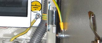
- connect the neutral and protective conductors with one screw (bolt) on the busbar in the shield;
- PE and N must be connected to different buses, and each wire from each apartment must be screwed with its own screw (bolt). It is necessary to take measures against loosening of bolts and protecting them from corrosion and mechanical damage (clause 1.7.139 of PUE 7).
This connection is used in modern power supply of residential premises or private houses. Which meets the requirements of PEU-7 (clause 7.1.13) for direct and alternating current networks with a voltage of 220/380 volts. After separation, combining them is strictly prohibited.
In a private house, we often receive two or four wires from overhead power lines. Most often there are 2 situations:
The point is to connect the zero and grounding at the input to all RCDs and automatic circuit breakers, and from this point lead the phase, neutral and ground to the consumers.
If the overhead power line is old, there is no need to connect the neutral and the ground (Chapter 1.7. PUE clause 1.7.59). Make a TT system (without connecting PE to N). In this case, be sure to use an RCD!
In both situations, each wire on the busbars must be tightened with its own bolt - do not put multiple PE or N conductors under one bolt (or screw).
Expert opinion
It-Technology, Electrical power and electronics specialist
Ask questions to the “Specialist for modernization of energy generation systems”
Let's analyze the situation with the circuits Even if three phases are installed in your house, this occurs in the private sector, for final consumption two wires are still used, zero and phase. Ask, I'm in touch!
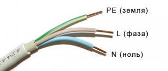
Cable color marking
This is one of the simplest methods. To determine what phase and zero are by color, you need to clearly know which shades correspond to what. You can use information about the standards adopted in the country.
It's no secret that each wire has an individual color. Therefore, recognizing zero should not be a particular problem. The knowledge gained will allow you to easily cope with the installation of a lighting fixture or installation of an outlet. This method is especially relevant for new buildings. After all, there, as a rule, wires are laid by experienced specialists who strictly comply with norms and standards. The IEC 60446 standard, adopted on the territory of the Russian Federation in 2004, strictly regulates the separation of phase, grounding and zero by color.
It is worth considering that:
- if the wire has a blue or blue-white tint, we can safely say that this is a working zero
- the protective zero is represented by cables in a yellow-green sheath
- other colors are characteristic of the phase. It can be red, brown, white or black. Other options are also possible.
This designation is successfully used in most cases. But if the wiring is old, or there are doubts about the professionalism of electricians, it is more advisable to use additional methods.
Options for determining phase/neutral conductors
Color coloring of wires as a main guide
This is the easiest and fastest way. To correctly classify zero and phase, you should know which wire color belongs to what. You will first need to study information about where the current standards for a particular country are clearly stated.
This method is very relevant in any new buildings, since now all electrical wiring is laid by specialists who carry out their work in accordance with all the requirements of established standards. For example, in Russia back in 2004, the “IEC60446” standard was adopted, which clearly defines the procedure for separating cables by color, namely:
- a yellow-green wire began to be designated as a protective zero;
- the working zero began to be called the blue/blue-white wire;
- phase - wires of other colors (for example, black, red, brown and others).
This designation is currently relevant.
An indicator screwdriver is an indispensable device
This tool is an integral part of the home electrician's kit. It is used both when performing electrical installation work, and when installing lighting fixtures indoors, or even in the process of simply replacing light bulbs.
The principle of its operation is the passage of capacitive current through the body of the screwdriver through the operator’s body.
Screwdriver elements:
- housing made of dielectric material;
- a metal tip in the shape of a flat screwdriver, which is applied to the wires when checking;
- neon indicator - a light bulb signaling the phase potential;
- current limiter - a resistor that reduces the current to a minimum value and acts as a protective mechanism: it protects a person from electric shock, and the device itself from failure;
- a contact metal pad that creates a closed circuit through a person to the ground.
The method of work is so simple that anyone, even a beginner, can cope with it. The indicator screwdriver works as follows. When the tip touches the phase contact (colored wire), the electrical circuit is closed - the neon lamp should light up. That is, a “message” is received about the presence of resistance, therefore, this cable is a phase. At the same time, it should not light up either at ground or at zero. If this happens, we can say with confidence that there are errors in the wiring diagram.
When working with such devices, you need to be extremely careful - do not touch exposed areas of conductors and indicator terminals that are under voltage.
The devices, in addition to their direct purpose - checking the phase wire - also perform a number of other auxiliary tasks: determining the polarity of DC voltage sources, the location of an electrical circuit break, and so on.
Multimeter - a reliable assistant
To calculate the phase using a tester, you need to switch it to the “voltmeter” mode and measure the voltage between all paired cable terminals. The connection of the probes to the protective zero and ground should indicate the absence of voltage. The voltage between the phase and any other wires should be 220 V.
Ways to identify wires:
So, in the first case, the voltmeter deviates from zero o. In another picture it shows the absence of voltage between zero and ground. And on the third, the voltmeter between the phase and the ground shows “0 V” since the conductor is not yet connected to the ground. The third case is rather an exception to the rule. This is possible, for example, in cases where the old cables of the building are at the stage of reconstruction. In a normal working electrical wiring system, the voltmeter should also show 220 V.
Using an incandescent lamp
Before starting work, you will need to assemble the testing device. It will consist of an ordinary light bulb, socket and wires. The lamp is screwed into the socket, and conductors are attached to the terminals of the socket. One of the wires will need to be grounded, for example, connected to a heating battery.
The essence of the method is to alternately apply a second (free) conductor to all tested conductors. If the light flashes, a phase wire has been found.
Therefore, to a greater extent, this method is appropriate for determining the functionality of electrical wiring and correct installation.
Household electrical wiring.
Initially, electricity is generated at a power plant. Then, through the industrial power grid, it enters the transformer substation, where the voltage is converted to 380 volts. The connection of the secondary windings of the step-down transformer is made according to the “star” circuit: three contacts are connected to the common point “0”, and the remaining three are connected to terminals “A”, “B” and “C”, respectively. For clarity, a picture is provided.
The combined contacts “0” are connected to the grounding loop of the substation. Also here the zero is split into:
- Working zero (shown in blue in the picture)
- PE conductor performing a protective function (yellow-green line)
The zeros and phases of the current from the output of the step-down transformer are supplied to the distribution panel of the residential building. The resulting three-phase system is distributed across panels in the entrances. Ultimately, a phase voltage of 220 V and a PE conductor, which performs a protective function, enters the apartment.
So, what is zero phase current ? A zero is a current conductor connected to the ground loop of a step-down transformer and serves to create a load from the current phase connected to the opposite end of the transformer winding. In addition, there is a so-called “protective zero” - this is the PE contact described earlier. It serves to drain current when a technical malfunction occurs in the circuit.
This method of connecting residential buildings to the city power grid has been proven for decades, but it is still not ideal. Sometimes malfunctions appear in the above system. Most often, they are associated with poor connection quality in a certain section of the circuit or a complete break in the electrical wire.
Phase and zero: their meaning in the power supply network
Electricity is supplied to consumer sockets from substations, which reduce the incoming voltage to 380 V. The secondary winding of such a transformer has a “star” connection - its three contacts are connected to each other at the “0” point, the remaining three outputs go to the “A” / “B” terminals "/"WITH".
The wires connected at point “0” are connected to “ground”. At the same point, the conductor is divided into “zero” (indicated in blue) and a protective “PE” cable (yellow-green line).
This model of wiring is used in all houses currently being built. It is called the “TN-S” system. According to this diagram, three phase cables and two indicated zeros are suitable for the distribution equipment of the house.
In houses, enterprises and buildings of old construction there is often no “PE” conductor and therefore the circuit turns out not to be five-wire, but four (it is designated as “TN-C”).
All electrical wires from the substations are connected to the panel, forming a three-phase system. Then there is a division into separate entrances. Each of the entrance apartments is supplied with only one phase voltage - 220 V (wires “O” / “A”) and a protective “PE” cable.
With this scheme, the entire load on the power supply system is distributed evenly, since on each floor of the house specific panels are wired and connected to a specific 220 V power line.
The supply voltage circuit is a “star”, which exactly repeats all the vector characteristics of the supply substation. When there are no consumers in the sockets, no current flows in this circuit.
This connection scheme has been worked out for years. It confirmed its right to use by being recognized as the optimal of all existing ones. However, in it, as in any device, mechanism or device, all kinds of breakdowns and malfunctions may periodically appear. As a rule, they are associated with poor quality electrical connections or complete cable breaks in some places in the circuit.
What happens in zero and phase when a wire breaks.
Line breaks quite often occur due to the fault of the craftsmen - they forget to connect a phase or zero. Such breakdowns are quite common. Also, quite often the process of zero burnout on the access panel occurs, for example, due to high load in the system.
If a break occurs in any part of the chain, the entire chain stops functioning, because it opens. In such situations, it does not matter at all which wire is damaged - phase or neutral. The same thing happens when there is a break between the distribution board of a high-rise building and the panel in the entrance. With such a gust, all consumers who were connected to this panel will be without electricity.
All the situations that we tried to describe above occur. They may seem complicated, but they pose no danger to humanity. After all, the break occurred in only one wire, so it is not at all dangerous.
A very alarming situation is when the contact between the ground loop at the substation and the middle point, to which all the voltage of the in-house panel is supplied, is lost.
It is in this embodiment that the electric current moves along the contours AB, BC, CA. The total voltage of these circuits is 380V. It is for this reason that a rather dangerous situation arises - one panel may have no voltage at all, because the owner will turn off all electrical appliances, and a very high voltage level will form on the other, about 380V. This can contribute to the failure of many devices, because they require a voltage of 220V.
Naturally, this situation can be avoided. There is a lot of inexpensive/expensive equipment that will protect your equipment from power surges. Such equipment also includes a voltage stabilizer. There are the following types of stabilizers:
- Single phase;
- Three-phase.
Operating principle of AC network
The AC network is divided into two components: the operating phase and the empty phase. The working phase is sometimes simply called the phase. The empty phase is called the zero phase or simply zero. It serves to create a continuous electrical network when connecting devices, as well as to ground the network. And the operating voltage is supplied to the phase.
When turning on an electrical appliance, it does not matter which phase is working and which is empty. But when installing electrical wiring and connecting it to the general house network, you need to know and take this into account.
The fact is that the installation of electrical wiring is done using either a two-core cable or a three-core cable. In a two-core one, one core is the working phase, the second is zero. In a three-wire system, the operating voltage is divided into two cores. This results in two working phases. The third core is empty, zero. The general house network is made of a three-core cable. The general electrical wiring diagram in a private house or apartment is also mainly made from a three-core wire. Therefore, before connecting apartment wiring, you need to determine the working and zero phases.
How to determine zero and phase on your own.
To determine the zero and phase of the current, there are special tester screwdrivers.
It works on the principle of passing low voltage current through the body of the person using it. The screwdriver consists of the following parts:
- Tip for connecting to the phase potential of the socket;
- A resistor that reduces the amplitude of the electric current to safe limits;
- An LED that lights up when there is a current phase in the circuit;
- Flat contact to create a circuit through the operator's body.
Phase and zero: concepts and differences
There is such a thing as tension. This word means the degree of electric field strength at a given point or circuit. Otherwise it is called potential. In very simple words, this is a kind of piston that gives an impetus to electrons so that they pass through the wires and light a light bulb in a chandelier.
In the common circuit (phase zero), the one that comes to the chandelier or socket, there are two wires. One of them is a phase. It is this wire that is live. A phase in electrical engineering is comparable to a positive in a car - it is the main power supply for the network.
Phase, neutral, ground in the socket
Zero is a wire that is not energized (this is exactly what distinguishes zero from phase). It is not overloaded during the power take-off process, but, nevertheless, electric current also flows through it, only in the direction opposite to the phase one. In the absence of voltage, it is safe in terms of electric shock to a person.
Zeroing in the apartment
This is the connection of the neutral cable with the neutral conductor of the electrical network and the device body. It is assumed that the procedure ensures faster disconnection of the device from the network when touching a dangerous place, if the voltage is above a certain threshold. But it is associated with an additional danger: if there is a zero break, all devices connected at that moment to the apartment’s network will have a phase (and not zero) on the surface, which creates a significant threat to the health of residents. Therefore, such installation work is strictly regulated.
Knowing what exactly is called a phase in an electrical network and how to detect it is extremely important when carrying out electrical installation work. Otherwise, there is a high risk of harming the health of the tenants or the condition of electrical appliances.
How to distinguish phase, zero, ground
The easiest way to determine the purpose of the conductors is by color marking. In accordance with the standards, the phase conductor can have any color, the neutral can be blue, and the ground can be yellow-green. Unfortunately, when installing electrics, color coding is not always observed. We must not forget the likelihood that an unscrupulous or inexperienced electrician can easily confuse phase and zero or connect two phases. For these reasons, it is always better to use more precise methods than color coding.
You can determine the phase and neutral conductors using an indicator screwdriver. When the screwdriver comes into contact with the phase, the indicator will light up, as electric current passes through the conductor. Zero has no voltage, so the indicator cannot light up.
You can distinguish zero from ground using a dial tone. First, the phase is determined and marked, then with a continuity probe you need to touch one of the conductors and the ground terminal in the electrical panel. Zero will not ring. When you touch the ground, a characteristic sound signal will be heard.
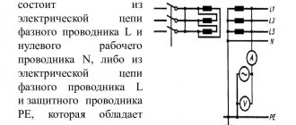
Determination of phase-zero loop resistance
To ensure the normal functioning of electrical appliances and check machines, it is necessary to periodically measure the resistance of the phase-zero loop. Because the primary causes of breakdowns of lighting devices are network overloads and short circuits. Measuring resistance allows you to quickly identify a malfunction and prevent a similar situation.
Not everyone knows what the concept of a “phase-zero loop” is. This phrase hides a circuit formed as a result of connecting the neutral wire located in a grounded neutral. The closure of this electrical network forms a phase-zero loop.
Resistance in this circuit is measured using the following methods:
- drop in voltage level in a disconnected circuit
- a drop in voltage level due to the resistance of an increasing load
- using a professional tool to interpret the short circuit in the circuit
The second method is used most often, as it is convenient, the ability to quickly measure resistance, and also safe.