At all stages of production, transmission, distribution and consumption of electrical energy in almost all sectors of the national economy, electrical devices play an important role.
Electrical devices (contactors, starters, relays, electromagnets) are part of automatic, semi-automatic and manual control systems for electrical power plants, electric drives, electric lighting devices, electrical technological installations, etc. They are used to control start-up, regulate rotation speed and implement electric braking electric motors. Electrical devices are used to regulate the currents and voltages of generators. They carry out the functions of monitoring and protecting installations that consume electricity.
Thus, the use of electromechanical devices allows you to control the operation of electrical and non-electrical objects according to a given program, as well as protect these objects from undesirable conditions - overloads, overvoltages, unacceptably high currents, etc.
Many electrical devices are designed to perform a single function in a control or protection system, but there are also multifunctional devices. The operation of electromechanical devices in automation systems is based on a number of physical phenomena: the interaction of ferromagnetic bodies in a magnetic field, the force interaction of a conductor with current and a magnetic field, the occurrence of EMF in coils and eddy currents in massive bodies of electrically conductive material when an alternating magnetic field appears, the thermal effect of electric current, etc.
The main parts of electrical apparatus are
- electrical contacts (fixed and moving, main and auxiliary),
- mechanical or electromagnetic drive of the contact group (bringing into contact and pressing moving and fixed contacts),
- control handles (buttons) and working windings. The electrical device is triggered, that is, it closes and opens contacts or connects the moving and stationary parts of the electromagnetic mechanism, under the influence of:
1) service personnel pressing control handles (buttons); in this case, the device is called manual or semi-automatic; 2) electrical quantities characterizing the operation of the controlled (managed) object, changing the current or voltage on the working windings; in this case the device is called automatic.
Depending on the functions that the device must provide, various requirements may be placed on it, but the main requirements are reliability and accuracy of operation: reliable connection of contacts, low electrical resistance at the junction of the contacts, accuracy of the dependence of the moment of operation on the value of the control current or voltage.
Switching devices for voltages up to 1000 V
Switching devices up to 1000 V are designed for switching electrical circuits in normal and emergency modes in single-, two- and three-phase AC networks with a frequency of 50 Hz and a rated voltage of 110, 220, 380 and 660 V.
Switching devices up to 1000 V include: circuit breakers and switches, fuses, contactors, magnetic starters and circuit breakers.
Switches and switches
Switches are designed for manually turning on and off electrical circuits of direct and alternating current with voltages up to 500 V inclusive and for rated currents up to 10,000 A.
The maximum current that a switch can turn off is usually less than the rated current. To increase the maximum switched current, switches are equipped with arcing chambers with arcing grids. In this case, the circuit breakers allow cutting off the current up to (1–1.25) I
nom.
A switch that is not equipped with a device for extinguishing the arc serves to relieve voltage - disconnecting the circuit without current and creating a visible break.
By design, there are one-, two- and three-pole switches.
The switches can be driven using a central handle, a side handle or remotely through a lever system. In installations for the auxiliary needs of power plants, switches with a manual lever drive are most widely used.
To reliably disconnect and protect the knives from burning, switches are made with momentary shutdown or with arc-extinguishing contacts. Instant shutdown is achieved using a torque knife connected by a spring to a parallel main knife. When disconnected, the main knife comes out first and stretches the spring. The speed of movement of the torque knife and the contact opening are determined by the parameters of the tripping spring. When using arc chutes, torque knives are usually not used.
Arcing contacts are used in DC switches at currents of more than 100 A and in all alternating current switches, where the speed of contact divergence and their solution have virtually no effect on the arc extinguishing conditions. These contacts are the last to be disconnected and serve to protect the main contacts from burning.
Extinguishing a DC arc (up to 75 A) occurs due to its mechanical stretching. At high currents, the arc is extinguished due to its movement by electrodynamic interaction forces. The shorter the knife, the greater the interaction force between the arc and the parts of the switch, which increases the switching capacity of the switch.
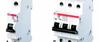
Rice. 4.1 Appearance of a switch with a protection function (switch-fuse)
The extinguishing of the alternating current arc is carried out due to the near-cathode electrical strength (150-250 V), which occurs when the current passes through zero. The length of the knife in AC switches is selected according to mechanical conditions.
The use of arc chutes ensures that the arc is extinguished when the rated currents are switched off by 220 V DC and 380 V AC switches. At voltages of 440 and 500 V, the switched currents are 0.5 I
nom.
Switch-fuses are designed to turn on/off the load and protect against short circuits and overloads (Fig. 4.1).
Switch-fuses consist of the following parts:
· three-pole base equipped with spring contact jaws for connecting cables;
· bases with arc-extinguishing chambers and protective screen of lower contacts;
· removable block handle with space for fusible inserts.
Switches are designed to switch electrical circuits.
Packet switches are small in size and easy to install; When switching, the release of flame and gases is eliminated. The contact system allows you to control a large number of circuits simultaneously. Such switches allow switching off rated currents.
Batch switches do not provide a visible circuit break, so in some circuits it is necessary to install switches.
Circuit breakers
A fuse is an electrical switching device designed to disconnect the protected circuit by destroying live parts specially designed for this purpose under the influence of a current exceeding a certain value (Fig. 4.2).
The shutdown process consists of heating the insert to the melting temperature and evaporation of the insert, the occurrence of an electric arc and its extinguishing with the restoration of the insulating properties of the gap,
In most fuses, the circuit is disconnected by melting the fuse link, which is heated by the current of the protected circuit flowing through it. After disconnecting the circuit, it is necessary to replace the burnt-out insert with a serviceable one. This operation is performed manually or automatically by replacing the entire fuse.
Fuses are characterized by the following indicators.
The rated current of the fuse-link, i.e. the current for which the fuse-link is designed for long-term operation.
Fuses with different rated currents can be inserted into the same fuse body, so the fuse itself is characterized by the rated current of the fuse (base), which is equal to the largest of the rated currents of the fuse links intended for this fuse design.
| b |
| A |
Rice. 4.2 PR series fuse:
A
- incision;
b
- ampere-second characteristic; 1 - fiber tube; 2 — fuse-link; 3 — brass bushing; 4 - bolt contact of the knife with the fusible insert; 5 — brass cap; 6 - copper contact knife
Low voltage fuses are manufactured for currents from milliamps to thousands of amperes and for voltages of 250, 500 and 660 V.
The fuse consists of a housing or load-bearing part, a fuse-link, a contact connecting device, an arc extinguishing device or an arc extinguishing medium (Fig. 4.2, a
).
The most important characteristic of a fuse is the current-protective or ampere-second characteristic of the fuse - the dependence of the fuse-link burnout time on the current (Fig. 4.2, b
).
There are minimum melting I
PP,min and rated
I
rated currents of the fuse link. The highest current at which the insert does not burn out within 1-2 hours is called the minimum melting current. Its value depends on the cross-section of the insert, the material and its length, the design of the fuse, the ambient temperature and is usually standardized.
The rated current of the fuse-link is taken to be 1.3-1.4 times less than its minimum fusing current to prevent disconnection of the circuit when the ampere-second characteristic of the insert is unstable due to oxidation of the metal of the insert, an increase in the contact resistance of the contacts, etc.
Fuse links are made from low-melting metals and their alloys - lead (200-327 ° C), zinc (420 ° C), as well as from refractory ones - copper (1080 ° C), less often silver (960 ° C).
To reduce the electrodynamic and thermal effects on the conductors and devices of the protected circuit, the fuse-link must burn out in the shortest possible time before the current increases to the shock value, i.e. it must limit the current. The shorter the fuse-link burnout time and the lower the current, i.e., the steeper the ampere-second characteristic, the higher the current-limiting effect of the fuse.
To reduce the melting time of the insert, it is given a flat special shape with several narrowed sections. With a sharp increase in current, the heating process of the insert can be considered adiabatic, i.e., without heat transfer, while the insert burns out in one or more narrowed places. To speed up melting, the “metallurgical effect” is also used, which consists of soldering small tin balls onto copper or silver insert wires, usually connected in parallel. When the low-melting balls melt, the refractory metal of the insert dissolves in them. After the insert burns out, an electric arc occurs, which must be extinguished in a short time. This depends on the design of the fuse and the method of extinguishing. In fuses with closed collapsible cartridges made of fiber without filler (type PR), the arc goes out due to high pressure (1000 N/cm2 or more) and the properties of the environment that arise in the cartridge during arc combustion and decomposition of the fiber (50% CO2, 40% Na) . In fuses with a filler (usually quartz sand) of the PN type, the arc goes out due to intensive cooling of the arc barrel by the filler and the pressure created by the arc in the narrow channels of the filler.
The maximum current that can open a fuse without causing damage is called the limiting current of the fuse.
Collapsible type fuses without filler are capable of disconnecting currents up to 10-20 kA at a source voltage of 220-500 V, and with filler - up to 100 kA at a network voltage of 380 V.
Fuses do not have opening contacts and drives, so they are used in combination with the simplest disconnecting devices for operational switching of circuits: switches, contactors, etc.
The main advantages of fuses are the simplicity and compactness of the design, cost-effectiveness, and the disadvantages are the need to replace a blown insert, the impossibility of automatic reclosure (AR) of a disconnected connection, and limited selectivity of action.
| Rice. 4.3 Non-separable filled fuse |
Bulk fuses type PN-2 (Fig. 4.3) are widely used for protecting power circuits up to 500 V AC and 440 V DC and are made of a porcelain tube, square on the outside and round on the inside, tube 1 has four threaded holes for screws, with which a cover 4 with a sealing gasket 5 is attached. The fusible insert 2 is welded by electric contact spot welding to the washers of the cut-in contact knives 3. The covers with asbestos gaskets hermetically close the tube.
The tube is filled with dry quartz sand 6. The fusible insert is made of one or more copper strips 0.15-0.35 mm thick and up to 4 mm wide. Slots 7 are made on the insert, reducing the cross-section of the insert by 2 times. To reduce the melting point of the insert, a metallurgical effect is used - tin balls are soldered onto copper strips 8. The melting point in this case does not exceed 475 °C. The arc occurs in several parallel channels (according to the number of inserts). This ensures the least amount of metal vapor in the channel between the quartz grains and the best conditions for extinguishing the arc in a narrow gap. Bulk fuses, like PR fuses, have a current-limiting property. To reduce the resulting overvoltages, the fuse-link has slots along its length, and their number depends on the rated voltage of the fuse (based on 100-150 V per area between the slots). Since the insert burns out in narrow places, the long arc turns out to be divided into a number of short arcs, the total voltage on which does not exceed the sum of the cathode and anode voltage drops. The filler in PN fuses is pure quartz sand (99% SiO2). Instead of quartz, chalk (CaCO3) can be used; sometimes it is mixed with asbestos fiber. When the arc is extinguished, the chalk decomposes, releasing carbon dioxide CO2 and CaO, a refractory material. The reaction occurs with the absorption of energy, which helps extinguish the arc. Sometimes gypsum (CaSO4) and boric acid are used for backfilling.
In bulk fuses, instead of porcelain tubes, tubes made of fiberglass impregnated with heat-resistant varnishes, steatite, or cast from plastics or insulating resins can be used.
Contactors
Contactors are remote-operating devices designed for frequent switching on and off of power electrical circuits under normal operating conditions. To protect against short-circuit currents, fuses or circuit breakers without remote control are installed in series with the contactor.
Contactors are manufactured for currents of 4-4000 A, voltage 220, 440, 750 V DC and 380, 660 (1140) V AC and allow 600-1500 starts per hour. Some special series of contactors allow up to 14,000 starts per hour. Contactors can be one-, two-, three- or five-pole.
Electromagnetic contactors are widely used in electrical installations. The contact system is switched on by an electromagnet.
Depending on the operating mode, contactors differ in application categories: AC-1, AC-2, AS-Z, AS-4, DC DS-1, DS-2, DS-Z, DS-4, DS -5 (GOST 11206-77E). Contactors of category AC-1 are designed for use in resistance electric furnace circuits and switch only the rated current. Contactors of category AC-2 are designed for starting electric motors with a wound rotor and switch a current of 2.5 I
nom.
Contactors of category AC-Z are designed for starting electric motors with a squirrel-cage rotor and for switching off rotating electric motors and switch a current of 6-10 I
nom.
Contactors of category AC-4 are designed for starting electric motors with a squirrel-cage rotor and for disconnecting stationary or slowly rotating electric motors; they switch currents of 6-10 I
nom.
Depending on the category, DC contactors are designed for switching currents from I
nom up to 10
I
nom.
Contactors can be designed to operate in intermittent, continuous, intermittent or short-term modes.
Contactors do not have devices that respond to overloads or short circuits. This function is performed by fuses and circuit breakers connected in series with the contactor and protecting the circuit from overloads and short circuits. The electrodynamic and thermal resistance of contactors is not standardized.
Unlike circuit breakers, contactors do not have mechanical devices that lock the contactor in the "on" position. In the on position, the contactor is held by an electromagnet.
The main elements of contactors are: main contacts, arc extinguishing device, electromagnetic system and auxiliary contacts.
Rice. 4.4. Electromagnetic contactor:
A
– electrical circuit of a single-pole contactor;
b
– conventional design diagram
In Fig. 4.4, a
shows the control circuit of a single-pole contactor.
The main contacts of the KM contactor are included in the motor circuit M, and the coil is included in the control circuit in series with the control buttons SB
1,
SB
2 and auxiliary contacts
SQ
.
On the design diagram (Fig. 4.4, b
) the contactor is shown at the moment of shutdown, when the voltage from the coil 15 installed on the core 14 is removed and the movable system, under the action of the spring 11, has returned to its normal position. The arc that occurs between contacts 2 and 7 is extinguished in chamber 5 with insulating partitions 4. The arc is drawn into the chamber due to the magnetic field created by a magnetic system consisting of a coil 16 connected in series to the main circuit, a steel core 1 and pole pieces 17 A flame arresting grille 3 is installed at the exit from the chamber, preventing ionized gases from escaping outside the chamber.
The contactor can be controlled using buttons, switches, relays, and control keys.
To turn on the contactor, voltage is applied to the coil terminals 13 by pressing the SB
1. A magnetic flux is created in the coil, attracting armature 10 to the core. A movable contact 7 is attached to the anchor, which, after contact with the fixed contact 2, slides along its surface, destroying the oxide film on the surface of the contacts. Pressure in the contacts is created by a spring 8. Contact pads 6 made of silver provide minimal contact resistance. In some cases, the linings are made of arc-resistant metal ceramics. The contactor is held in the on position by its coil. After turning on the contactor, auxiliary contacts 12 (SQ) are closed, shunting the SB1 button, so opening the start button does not break the circuit of coil 15 (KM).
The armature 10 is provided with a non-magnetic brass gasket 9, which reduces the attractive force caused by the residual induction in the core. Thus, when the voltage is removed from coil 15, the armature does not “stick”. If the voltage in the control circuit significantly decreases, or if it disappears, the contactor is automatically switched off.
To turn off the contactor, just press the SB
2, which will open the power circuit of coil 15.
The protection of the electric motor in the considered circuit is carried out by the QF
. Electromagnetic contactors of general industrial series include the following types: alternating current KT, KTP, KTV; direct current KP, KPV, efficiency; direct and alternating current KM, RPK, KN.
Rotary type contactors of the KT6000 series with slot chambers and magnetic blast and KT7000 with arc extinguishing grilles for heavy duty operation in alternating current circuits (categories AC-Z, AC-4) are widely used.
In Fig. Figure 4.13 shows the design diagram of the KT6000 contactor. On a metal rail 14, fixed contact units 12 are mounted together with magnetic blowing systems - coil 10, core 9, side steel plates 2 and arc-extinguishing chambers 3. On rail 14, the electromagnet core, the fixed part of the auxiliary contacts 1 are mounted, and bearing supports 5 for the main shaft are mounted. 6. The outer part of the shaft 8 is insulated, movable contacts 11 with contact springs 13 and flexible connections 7 (three poles), a movable part of auxiliary contacts 1 and an electromagnet armature 4 are installed on it. The contactor operates as described above. Contactors of this series are available for voltages of 380 and 660 V for currents of 100-1000 A, allow up to 1200 starts per hour, switching current at a rated voltage of up to 8 I
nom. Contactors of the KM2000 series are manufactured for direct current 220 V up to 350 A and alternating current 380 V up to 600 A. The main contacts are bridge contacts, an arc-extinguishing chamber with magnetic blast. The electromagnet coil in these contactors is powered from a direct current network or rectified voltage from a rectifier assembled on semiconductor diodes using a single-phase bridge circuit.
Rice. 4.4. Structural diagram of the contactor KT-6000
To extinguish the arc, contactors use grids with plates made of copper and insulating arc-resistant material.
This system ensures fast arc extinguishing, which contributes to low contact wear. In addition to the main contacts, the contactor has several auxiliary block contacts to coordinate operation with other devices.
Basic technical data of contactors:
1) rated current of the main contacts (current of intermittent-continuous operation);
2) limit switchable current;
3) rated voltage;
4) mechanical wear resistance (determined by the number of switches on and off of the contactor without repairing or replacing its components. The current in the circuit is zero. In modern contactors, mechanical wear resistance is equal to (10–20) × 106 operations);
5) electrical wear resistance (determined by the number of switching on and off of the current-carrying circuit, after which replacement of worn contacts is required. In modern contactors, electrical wear resistance is equal to 2–3 million operations);
6) permissible number of starts per hour;
7) own turn-on time (consists of the time of flow increase to the start-up flow value and the time of armature movement);
own shutdown time (time from the moment the electromagnet is de-energized until the contacts open).
Magnetic starters
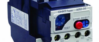
A starter is a switching device designed to start, stop and protect electric motors.
Magnetic starters consist of an electromagnetic contactor, built-in thermal relays and auxiliary contacts. The most common series are PMB, PMA, PA. Starters can be reversible and non-reversible, in an open, protected and dust-splash-proof design, with or without thermal relays. Magnetic starters are used to control AC electric motors with voltages up to 660 V and power up to 75 kW.
Rice. 4.6 PAE series magnetic starter:
A
– electrical diagram;
b
– design diagram
The electrical and structural diagram of the PAE series magnetic starter is shown in Fig. 4.6. When the SB1 button is pressed, power is supplied to the contactor coil KM(5) through the opening contacts of the thermal relays KST1, KST2 and the SB
2. The armature of the electromagnet 6 is attracted to the core 4, rotating around the
O
SQ
are closed (Fig. 4.6,
a
), which bypass the button
SB
1. When the electric motor is overloaded, both or one thermal relay 11 is activated, the coil circuit is opened by contacts KST1 and KST2.
In this case, the armature 6 is no longer held by the core and, under the influence of its own mass and the spring 7, the movable system moves to the off position, opening the contacts. A double break in each phase and a closed chamber 10 provide arc extinguishing without special devices. The starter is turned off in exactly the same way when the SB
2 button is pressed.
Shock-absorbing spring 3 protects the moving part from sudden shocks when turned on. All parts of the starter are mounted on a metal base 1.
To protect the electric motor from short circuit, fuses are included in the circuit ( F
).
The magnetic starter protects the motor from overload using thermal relays and turns it off when the voltage drops to 50 - 60% U
n.
When the electric motor is overloaded, the thermal relay elements heat a bimetallic plate made of alloys having different linear expansion coefficients, which bend under load and open the coil circuit. Magnetic starters are not designed to break the circuit in the event of a short circuit, so fuses are installed in series with them.
Circuit breakers
The automatic switch is designed for switching circuits in emergency modes, as well as infrequent (from 6 to 30 per day) operational switching on and off of electrical circuits (GOST 9098–78E).
Circuit breakers usually perform the functions of protective devices in the event of short circuits or overloads (overcurrent circuit breakers), reduction or disappearance of voltage (undervoltage circuit breakers), or changes in the direction of power or current transmission (reverse current or reverse power circuit breakers). Regardless of the functions performed, circuit breakers are divided according to their own response time t
s.v (time from the moment the command is given until the contacts begin to open) to normal
t
c.v = 0.02–0.1 s), selective (
t
c.v is adjustable to 1 s) and high-speed, having a current-limiting effect (
t
s. .in no more than 0.05 s).
The actual response time depends on the design of the circuit breaker opening mechanism, the force of the tripping springs, the mass of the moving system and the path of movement of this mass until the contacts begin to open.
Generator field suppression machines (AGGs) are included in a separate group.
Automatic switches are manufactured for rated currents up to 6000 A, and individual series up to 20000-30000 A and for rated voltages up to 660 V AC. High-speed circuit breakers are manufactured for rated voltages up to 3300V DC. The breaking capacity of automatic circuit breakers reaches 200-300 kA.
Automatic switches are made one-, two-, three-pole and have the following structural components.
The contact system can be three-stage (with main, intermediate and arc-extinguishing contacts), two-stage (with main and arc-extinguishing contacts) and, when using cermets, single-stage. The arc extinguishing system can consist of chambers with narrow slots or chambers with arc extinguishing grids.
Combined arc extinguishing devices - slot chambers in combination with an arc extinguishing grid are used to extinguish the arc at very high currents (Fig. 4.7).
Automatic switches are manufactured with manual and motor drives, in stationary or withdrawable versions.
The circuit breaker drive is used to turn on and automatically turn off; it can be manual, direct action or remote (electromagnetic, pneumatic, etc.).
Circuit breakers have direct-acting relays called trip units.
Releases are electromagnetic or thermo-bimetallic elements that serve to disconnect the circuit breaker through a free tripping mechanism in case of short circuit, overload and loss of voltage in the primary circuit.
The free tripping mechanism consists of levers, latches, rocker arms and tripping springs and is designed to disconnect the circuit breaker, as well as to eliminate the re-closing of the circuit breaker due to a short circuit during a long-lasting switching command.
Disconnection can occur without a time delay or with a delay. By own shutdown time t
s.v (the interval from the moment when the controlled parameter exceeds the value set for it until the moment the contacts begin to diverge) a distinction is made between normal switches (
t
s.v = 0.02–1 s), switches with a time delay (selective) and high-speed switches (
t
s.v < 0.005 s).
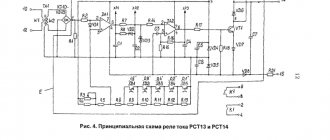
Rice. 4.7 Schematic section of the A3100 series circuit breaker:
1- base; 2 - cover; 3 - tire; 4 - fixed contact; 5 - movable contact; 6 - copper plate; 7 - flexible conductors; 8 — tires; 9-11 - overcurrent releases; 12 — thermal current releases; 13 - insulated roller or insulating traverse; 14–16 — levers of the free release mechanism; 17 — handle; 18 — chamber with arc extinguishing grid; 19 — disconnecting spring;
20 - latch
Normal and selective circuit breakers do not have a current-limiting effect. High-speed switches, like fuses, have a current-limiting effect (see Fig. 4.7), since they turn off the circuit before the current in it reaches the value I
u.
Selective circuit breakers allow for selective protection of networks by installing circuit breakers with different time delays: the smallest at the consumer and increasing stepwise towards the power source.
The circuit breaker can be equipped with a switch having auxiliary contacts that are used in the control, interlocking and signaling circuits of the circuit breaker.
The switch is designed for switching the maximum switched and switched currents in the cycle of operations O-P-VO-P-VO at rated voltage. Here O - off, P - pause (<= 180 s), VO - on, off.
Previous13Next
WHAT HAPPENS WHEN WE FIGHT Without understanding the differences that exist between men and women, it is very easy to lead to a quarrel...
System of Protected Areas in the USA The study of specially protected natural areas (SPNA) in the USA is of particular interest for many reasons...
WHAT IS CONFIDENT BEHAVIOR IN INTERPERSONAL RELATIONSHIPS? Historically, there are three main patterns of differences that exist between...
WHAT AND HOW THEY WRITTEN ABOUT FASHION IN MAGAZINES AT THE BEGINNING OF THE XX CENTURY The first issue of the Apollo magazine for 1909 began, in fact, with a policy statement from the magazine’s editors...
Didn't find what you were looking for? Use Google search on the site:
The following electrical devices are distinguished by purpose:
1) switching (disconnectors, switches, switches); 2) protective, the main purpose of which is to protect electrical circuits from unacceptably high currents, overvoltages, voltage drops, etc. (fuses, protection relays); 3) ballasts, designed to control electric drives and other industrial consumers of electricity (contactors, starters, control relays); 4) monitoring and regulating, designed to monitor and maintain the main process parameters (sensors and relays) in a given range; 5) electromagnets (power), used to hold or move objects in the production or management process.
This chapter discusses electrical devices (relays, starters, contactors and electromagnets) and some control and regulation circuits that use electromechanical devices.
First of all, let's consider the features of the operation of electrical contacts and the operation of the electromagnetic mechanism - the drive of the contact group of electrical devices.