Purpose and where to use
The use of disconnectors in the energy sector to break circuits is dictated, first of all, by safety considerations. They are used to make connections to contact networks for supplying current from supply lines. These mechanisms also serve to safely change the interconnection patterns of circuit sections.
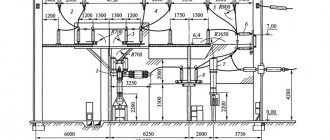
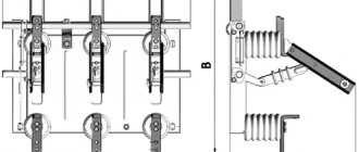
Figure 1 shows a section of a line with high-voltage disconnecting devices.
Figure 1. Line section with high-voltage disconnectors
The switching mechanisms under consideration have two important qualities that allow you to control the switching process:
- The ability to visually monitor the position of moving contacts at disconnection points.
- The absence of a mechanism allowing the possibility of free (arbitrary) release. The use of manual drives ensures that the specialist performs the planned operation of de-energizing or connecting the electrical network at the right time.
This design of the disconnector allows maintenance personnel to quickly assess the condition of the working parts of the switching mechanism before switching on, as well as visually monitor the position of the contact knives in a specific situation. Disconnectors always operate using high voltage switches, both outdoors and indoors.
Such devices can be used to switch transformers operating at no-load, as well as to disconnect lines with circulating pickup currents. With appropriate shunting devices, it is possible to disconnect live electrical circuits or turn off low-power transformer load currents. In this case, an arc discharge is always observed at the initial stage of shutdown or before switching on, when the contacts approach the breakdown distance.
The arcing time is reduced by the presence of contact springs. An exception is the class of load switches, the design of which includes autogas arc extinguishing devices - VNA. Such switches can be used as high-voltage disconnectors, which are used for switching sections of circuits up to 10 kV. (Fig. 2).
Figure 2. High-voltage load switch VNA
Main Applications
High voltage circuit disconnectors are used in many applications. With their help they serve:
- networks of complete transformer substations, including mobile transformer substations;
- family of complete switchgears KRU and KRUN;
- capacitor units;
- prefabricated chambers designed for one-sided maintenance;
- Main switchboards, input and distribution cabinets and other equipment.
The ability of three-pole and single-pole disconnectors to switch charging currents of overhead wires and cable lines, turn on and off induction currents of power transformers, cut off equalizing currents, and disconnect circuits with small load currents makes these devices indispensable in various power systems.
The areas of application of high-voltage disconnectors are regulated by PTEEP. The rules allow their use in networks of 6 - 10 kV, to switch on or off load currents up to 15 A or equalizing currents up to 70 A.
Load switches
What are load switches?
The load switch is a three-pole AC switching device for voltages above 1 kV, designed to interrupt operating current, and equipped with a drive for manual or automatic control.
Load switches are not designed to interrupt short-circuit current, but their making capacity corresponds to the electrodynamic resistance during short circuits. In 6-10 kV distribution networks, load switches are often called switches with a breaking capacity of less than 20 kA.
A load switch is a high-voltage switching device that, in terms of the level of permissible switching currents, occupies an intermediate position between a disconnector (switching under load is prohibited, with the exception of transformers and lines being switched on at idle) and a switch (oil, vacuum, air, electromagnetic, SF6) that is capable of disconnecting without damage to both rated load currents and overcurrents in emergency modes. The load switch allows switching the rated current, but is not designed to interrupt currents during a short circuit. Overcurrents in such switches are switched off using special fuses.
Load switch drive
The drive of the load switches can be muscular, directly switching on and off from a pre-tensioned spring. Sometimes an electric activation drive and a remote shutdown solenoid are used.
Types of load switches
- Autogas
- Vacuum
- SF6
- Air
- Electromagnetic
Application
Load switches are installed in 6-10 kV switchgears and substations and allow switching up to several MVA, depending on the design and rated current.
Load switches are used in connections of power transformers on the high voltage side (6-10 kV) instead of power switches, if this is possible under the operating conditions of the electrical installation. Since they are not designed to cut off short-circuit current, the functions of automatically turning off transformers in the event of their damage are assigned to fuses or to switches belonging to previous links in the system, for example, to linear switches located closer to the energy source.
In distribution networks, the most common designs of load switches (VNR, VNA, VNB) with gas-generating type extinguishing devices.
Advantages
- Ease of manufacture and operation;
- Significantly lower cost compared to other switches - several times (especially for gas switches);
- Possibility of switching off and switching on rated load currents;
- Availability of cheap overcurrent protection in the form of fuses. usually filled with quartz sand (type PC, PKT);
- The presence of a visible gap between the contacts, which eliminates the installation of an additional disconnector (a visible gap is necessary for the safety of work on the outgoing line).
Flaws
- Switching only rated powers;
- Short service life (for gas-type load switches).
Design and principle of operation
The creation of a high-voltage disconnector was driven by the need for a switching mechanism capable of providing a safe and visually observable break in high-voltage energized circuits. The design of such a device is based on high reliability of contacts, ensuring the circuit is closed and opened in all weather conditions.
The design of the high-voltage disconnector does not provide for the presence of spark-extinguishing elements. Therefore, in order to prevent the formation of a high-power electric arc that can destroy contacts, the devices are connected in series with high-voltage load switches. Before disconnecting the desired line, use a switch to turn off the load.
The disconnector design consists of a rigid load-bearing frame on which the following elements are mounted:
- a system of fixed insulators located on each side of the break for each phase wire;
- static contacts and contact knives that provide circuit closure and opening;
- mechanism for controlling moving contacts (knives);
- blocking elements.
Disconnectors intended for switching circuits whose voltage exceeds 110,000 V, consist of two contact movable half-blades, separated in opposite directions. The distance between the separated contacts is quite large, which eliminates the breakdown of this space in cases of unauthorized activation of the switch.
Depending on the purpose, the devices in question can be three-pole or single-pole. Three-pole disconnectors have three pairs of contacts. In a single-pole disconnector there is only one pair: a fixed contact and its contactor - a contact knife.
An example of a three-pole disconnector is shown in Figure 3.
Figure 3. Three-pole switch with vertical rotation of knives
Despite the fact that the radios operate with the load disconnected, the possibility of the presence of dangerous induced or capacitive currents cannot be excluded. In order to ensure complete safety for personnel, grounding blades are used, which are mounted on one platform and can perform their intended protective function only after the load switch is disconnected and the contacts connecting the serviced area to the live line are disconnected. Otherwise, a short circuit occurs between the grounded wires.
In order to eliminate damage caused by grounding blades as a result of accidental supply of rated currents, many models are equipped with locking mechanisms. The mechanisms block the movement of the knives when the grounding device is not removed or when the load is on. Most often, mechanical locking is used, but there are also electromagnetic and even hydraulic locking mechanisms. There are models with combined blocking elements.
For indoor installation
ARE USED:
- in order to visualize the connection and disconnection, and the actual break of previously de-energized sections of the electrical circuit, for the safe repair of equipment built into the power transmission line network;
- to break electrical circuits operating under low voltage, where the possibility of a discharge arc between the contact knives is excluded;
- for grounding previously disconnected areas when using stationary grounding conductors.
The devices are designed to operate in alternating current networks with a frequency of 50 and 60 Hz and voltages of 6 and 10 kV.
SINGLE-POLE - type RVO, RVK, RVR, RVP R
— disconnector;
B
- for indoor installation;
O
- single-pole;
P
- vertical chopping type;
K
- box-section current-carrying system;
P
- translational movement of the main knives. Available for currents up to 600 A. The numbers in the name mean voltage (kV) and current (A). The knife rotates through an angle of up to 100 and is held in the off position only by its own weight. The angle of rotation of the knife is fixed by a limiter. For the same series at 1000 A, in order to reduce the effort of pulling out the knife, an intermediate shaft was introduced.
| Single pole | ||||||
| Brand | Durability, kA | Dimensions, mm | Weight, kg | |||
| Electrodynamic (amplitude) | Thermal | Length | Width | Height | ||
| RVO-10/400 | 41 | 16 | 468 | 72 | 156/429 | 5,9 |
| RVO-10/630 | 52 | 20 | 468 | 72 | 160/433 | 6,3 |
| RV O-10/1000 | 100 | 40 | 480 | 92 | 163/440 | 11 |
| RLVOM-10/1000 | 100 | 40 | 486 | 380 | 199/460 | 14…17 |
| RV K-10/2000 | 85 | 31,5 | 560 | 350 | 280/500 | 26 |
| RVR(Z)-10/2500 | 125 | 45 | 1050 | 470 | 318/545 | 65 |
| RVR(Z)-10/4000 | 200 | 71 | 610/1050 | 470 | 318/545 | 65 |
| RVR(3)-20/6300 | 260 | 100 | 910/1400 | 700 | 680/1050 | 222 |
| RVR(3)-20/8000 | 320 | 125 | 1400 | 700 | 680/1050 | 238 |
| RVP(3)-20/12500 | 490 | 180 | 1600 | 820 | 857 | 625 |
| RV K-3 5/2000 | 115 | 45 | 980 | 700 | 550/1010 | 74 |
THREE-POLE - types RV, RVZ, RVF and RVFZ are three current conductors mounted on one frame with a common shaft, rods and drive lever.
RVFZ - symbol: F - figured; Z - with grounding knives.
The conductor consists of two fixed contacts and a movable knife connecting them. The knife is held in the on position by rods and a shaft. By rotating the shaft through a PR-P type drive (front connection) or PR type (10 - rear connection; 11 - front connection), the movable knives are turned on or off. The devices are installed in alternating current networks with a frequency of 50 Hz and voltages of 6 and 10 kV.
| Brand | Variant of arrangement of grounding knives | Option for bushing arrangement | Overall dimensions, mm, no more | Weight, kg, no more | ||
| L | H | B | ||||
| RV 10/1000 U3 | — | I var. – without bushings. | 654 | 199 | 472 | 28 |
| RV 10/630 U3 | 182 | 464 | 25 | |||
| RVZ 10/1000 I U3 | I var. – grounding blades on the side of detachable contacts RVS | I var. – without bushings. | 704 | 197 | 622 | 30 |
| RVZ 10/630 I U3 | 186 | 589 | 28 | |||
| RVZ 10/1000 II U3 | II var. – grounding blades on the side of the hinge contacts | I var. – without bushings. | 197 | 622 | 30 | |
| RVZ 10/630 II U3 | 186 | 589 | 28 | |||
| RVZ 10/1000 III U3 | III var. – grounding blades on both sides | I var. – without bushings. | 744 | 197 | 745 | 33 |
| RVZ 10/630 III U3 | 186 | 713 | 31 | |||
| RVF 10/1000 II U3 | — | II var. – bushings on the side of the hinge contacts. | 722 | 202 | 437 | 34 |
| RVF 10/630 II U3 | 32 | |||||
| RVF 10/1000 III U3 | — | III var. – bushings on the detachable contact side. | 437 | 34 | ||
| RVF 10/630 III U3 | 32 | |||||
| RVF 10/1000 IV U3 | — | IV var. – bushings on both sides | 406 | 39 | ||
| RVF 10/630 IV U3 | 37 | |||||
| R V F Z 10/1000 I-II U3 | I var. – grounding blades on the side of the detachable contacts | II var. – bushings on the side of the hinge contacts. | 199 | 649 | 39 | |
| R V F Z 10/630 I-II U3 | 35 | |||||
| R V F Z 10/1000 II-II U3 | II var. – grounding blades on the side of the hinge contacts | II var. – bushings on the side of the hinge contacts. | 39 | |||
| R V F Z 10/630 II-II U3 | 35 | |||||
Option for the location of grounding knives: I - on the side of the detachable contacts;
II - from the side of the hinge contacts; III - on both sides. Option for arrangement of bushings: II - on the side of the hinge contacts; III - from the side of detachable contacts; IV - on both sides
Principle of operation
Connection or disconnection of the switched electrical circuit is ensured by turning the contact knives. Depending on the design, the moving contacts can be rotated vertically or horizontally. The drive that imparts force to the rotating mechanism is a rod with a handle, with the help of which the operator controls the contact knives. The drive handles are mounted directly on the supports under the disconnector.
Manual control is used mainly on overhead lines up to 6 kV. Knives on lines of 110 kV and above are controlled by electric drives using metal cabinets located at a safe distance.
Why do you need a disconnector?
A disconnector is a switching device whose sole purpose is to create a visible break in the electrical circuit during repair or maintenance work.
Disconnector RVR-10 for 5000 A
Disconnectors owe their appearance to regulatory documents: “Rules for the Construction of Electrical Installations” (RUE) and “Rules for the Technical Operation of Consumer Electrical Installations” (RTE). These regulations require that when carrying out any work on electrical equipment, except for disconnecting the line, a visible break in the circuit must be created and the area where the work is being carried out must be grounded.
The creation of a visible break is caused by the fact that when the line is disconnected, it is not always possible to verify the complete absence of voltage in the circuit.
For example, when turning off the voltage using vacuum, oil or SF6 circuit breakers, you cannot be sure that the circuit is really completely open, since the contacts of such switches are located in a tank with an arc-extinguishing medium (oil, SF6 gas, vacuum), which excludes a visual check of their condition.
In addition to creating a visible circuit break, it is also necessary to ground the section of the line on which work is being carried out. To do this, you can use a special device - a ground electrode. However, most often this function is assigned to the disconnector, providing it with grounding contacts (knives), which, synchronously with the opening of the main contacts of the disconnector, ground the line on which the disconnector is installed.
The number and location of grounding blades may vary. Grounding blades can be located (a) on the side of the incoming line, (b) on the side of the outgoing line, (c) on both sides of the disconnector.
Considering that the disconnector can only disconnect a de-energized line, grounding the line cannot lead to dangerous consequences.
FIND OUT PRICE
Send a request in any form by email. During the day we will prepare an offer for you with cost and delivery time.
Or just call us at +7 910-973-00-28 Send a request...
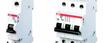
Classification
The domestic industry produces high-voltage disconnectors of various types. They can be classified according to the following criteria:
- by number of poles;
- type of contact knife (rotary, chopping, swinging);
- installation location (open space or room);
- by control method: manual (using an insulating rod or levers), electromechanical, hydraulic, pneumatic.
In addition, devices differ in rated voltage and rated current for which they are designed. Products come with grounding switches (disconnectors RVZ, Fig. 4), with figured knives (RVF) and others.
Figure 4. RVFz 1063
The type of device can be determined by its designation.
The letters indicate:
- P – type of product, in this case a disconnector;
- N – external;
- G – horizontal installation;
- L – linear;
- Z – disconnector with grounding blades. The numbers 1, 2... indicate the number of grounding conductors;
- D – with two support-insulating columns;
- The numbers 10, 35, 110, 220 mean the rated voltage in kilovolts.
For example, RV is an internal disconnector, and the abbreviation RLND means that this is a linear type of device with two support-insulating columns for outdoor use.
For outdoor installation
External, man-made environmental influences, natural and climatic operating conditions, impose certain requirements on the design of the disconnector.
The main requirements include: the presence of sufficient insulation in a polluted and humid environment, and mechanical strength when contact pairs become icing, often using built-in ice-breaking devices. Explanation of the abbreviation in brand designations:
- D - two-column;
- 3 - with grounding knives;
- L - linear;
- N - outdoor installation;
- O - single-pole;
- R - disconnector.
Outdoor horizontal rotary type disconnectors of the R L N D series are used:
- for the purpose of visualizing connection/disconnection, and the actual rupture of previously de-energized sections of the electrical circuit, for the safety of work in networks of high-voltage power lines;
- to break electrical circuits operating under low voltage, where the possibility of a discharge arc between the contact knives is excluded;
- for grounding previously disconnected areas when using stationary grounding conductors.
For these types, the rated voltage is 10 kV, but if necessary, RLND disconnectors can operate up to 750 kV.
Structurally, the RLND has one or two stationary grounding conductors. The connection between the main and grounding circuits is opened through lamella contacts, the pressure in which is created by springs.
Control is carried out by manual drives type PRN(Z)-10UHL1 or drives type PR-2BUHL1
Characteristics of disconnectors rlnd
| Name and type | Characteristics | |||
| Thermal resistance current, kA | Limit through current, kA | Weight, kg | Accessory drive, type | |
| with a movable contact terminal on a rotary column without grounding conductors | ||||
| R L N D-10B/630 UHL1 | 12,5 | 31,5 | 31 | PRG-2UHL1 |
| R L N D-10B/315N T1 | 10 | 25 | 30 | PRG-2T1 |
| R L N D-10B/630N T1 | 12,5 | 31,5 | 31 | — // — |
| R L N D-10B/400N UHL1 | 10 | 25 | 35 | PRG-2UHL1 |
| R L N D-10.IV/400N UHL1 | 10 | 25 | 28 | — // — |
| with a movable contact terminal on the rotary column and with one grounding switch on the side of the rotary column | ||||
| R L N D.1 -10B/315N T1 | 10 | 25 | 39 | PRG-2BT1 |
| R L N D.1 -10B/630N T1 | 12,5 | 31,5 | 40 | PRG-2BT1 |
| R L N D.1 -10B/400N UHL1 | 10 | 25 | 39 | PRG-2BUHL1 |
| R L N D.1 -10.IV/400N UHL1 | 10 | 25 | 36 | — // — |
| R L N D.1 -10B/630 UHL1 | 12,5 | 31,5 | 40 | — // — |
| with a movable contact terminal on a rotating column and with two grounding switches | ||||
| R L N D.2-10B/400N UHL1 | 10 | 25 | 43 | PRG-2BUHL1 |
| R L N D.2-10. IV/400N UHL1 | 10 | 25 | 40 | — // — |
| R L N D.2-10B/630 UHL1 | 12,5 | 31,5 | 50 | — // — |
Outdoor horizontal-rotating type R L N D-I series are used for:
- visualization of connection and disconnection, and real rupture of previously de-energized sections of the electrical circuit, for the safe repair of equipment built into the power transmission line network;
- breaking electrical circuits operating under low voltage, where the possibility of a discharge arc between the contact knives is excluded;
- grounding of previously disconnected areas when using stationary grounding conductors.
Structurally, the product has one or two stationary grounding conductors.
The connection between the main and grounding circuits is opened through lamella contacts, the pressure in which is created by springs. R L N D-I-10B is made on porcelain insulators, R L N D-I-10.II and R L N D-I-10-.IV are made on polymer insulators (with tracking-erosion-resistant coating) having high discharge characteristics in dirty and wet conditions and mechanical characteristics that ensure reliable operation under seismic impacts up to 9 points on the MSK-64 scale.
RLND-I at 200 A are controlled by a manual drive PRNZ-10UHL1, and at 400 A - by a manual drive type PRNZ-10UHL1 or a block manual drive PR-2BUHL1. The drives have a mechanical interlock between the main knives and the grounding switches.
| Name and type | Characteristics | |||
| Thermal resistance current, kA | Limit through current, kA | Weight, kg | Accessory drive, type | |
| with a fixed contact terminal on a rotating column without grounding conductors | ||||
| R L N D- I-10B/400N UHL1 | 10 | 25 | 33 | PRG-2UHL1 |
| R L N D- I-10.IV/400N UHL1 | 10 | 25 | 23 | — // — |
| R L N D- I-10B/ 200 UHL1 | 6,3 | 15,75 | 30 | PRN-10MU1 |
| R L N D- I-10.IV/ 200 UHL1 | 6,3 | 15,75 | 20 | — // — |
| R L N D- I-10/ 200 UHL1 | 6,3 | 15,75 | 30 | — // — |
| R L N D- I-10/ 400 UHL1 | 10 | 25 | 30 | PRG-2UHL1 |
| with a fixed contact terminal on the rotary column and with one grounding switch on the side of the rotary column | ||||
| R L N D- I.1-10B/400N UHL1 | 10 | 25 | 39 | PRG-2BUHL1 |
| R L N D- I.1-10.IV/400N UHL1 | 10 | 25 | 34 | — // — |
| R L N D- I.1-10B/ 200 UHL1 | 6,3 | 15,75 | 43 | PRN3-10UHL1 |
| R L N D- I.1-10.IV/ 200 UHL1 | 6,3 | 15,75 | 34 | — // — |
| R L N D- I.1-10/ 200 UHL1 | 6,3 | 15,75 | 34 | — // — |
| R L N D- I.1-10/400 UHL1 | 10 | 25 | 39 | PRG-2BUHL1 |
| with a fixed contact terminal on a rotating column and with two grounding switches | ||||
| R L N D- I.2-10B/400N UHL1 | 10 | 25 | 39 | PRG-2BUHL1 |
| R L N D- I.2-10. IV/400N UHL1 | 10 | 25 | 38 | — // — |
| R L N D- I.2-1 0B/200 UHL1 | 6,3 | 15,75 | 43 | PRNZ-10UHL1 |
| R L N D- I.2-1 0. IV/200 UHL1 | 6,3 | 15,75 | 38 | — // — |
| R L N D- I.2-1 0/200 UHL1 | 6,3 | 15,75 | 38 | — // — |
| R L N D- I.2-1 0/400 UHL1 | 10 | 25 | 39 | PRG-2BUHL1 |
Requirements
The main requirement for all high-voltage disconnectors is a design that provides for such a disconnection when the circuit break is clearly visible. Devices used to disconnect lines over 1 kV are subject to the requirements of GOST R 52726-2007, providing:
- thermal and electrodynamic stability of the structure;
- high quality insulation, capable of operating in various atmospheric conditions and withstanding all kinds of overvoltages;
- reliable switching on or off under all permissible conditions, including icing of structural elements;
- simplicity of design, ensuring reliable disconnection, ease of installation and operation.
Separate requirements apply to compliance with installation features, operating rules and preventive measures to keep disconnectors up to date.
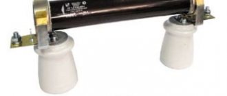
Exhaust fuses-disconnectors PRVT type
Fuse-disconnectors of the PRVT-10 series are designed to protect power transformers and distribution systems from short circuits and extreme overload currents, as well as to switch on and off sections of the electrical circuit (with an isolated or grounded neutral) with the load disconnected using an operating rod.
The fuse-disconnector is made in the form of a single-pole device consisting of a porcelain insulator, at the ends of which a contact system is attached to brackets for installing a replaceable element with a fuse-link.
In case of overload and short circuit currents, the fuse link burns out, the holder of the replaceable fuse-disconnector element automatically tilts back, thereby creating a visible gap. Thus, the device performs simultaneous functions of a protective device and a disconnector.
Replaceable elements are made with two types of time-current characteristics: type “K” - fast; type “T” – slow, which allows for selectivity of protection.
The delivery set of PRVT for 3 poles includes 19 replaceable elements and 1 spare cartridge.
The design of fuse-disconnectors ensures:
- reliable fixation of the knife cartridge in the upper contact in the on position and quick tilting of the cartridge when disconnected;
- the ability to quickly and conveniently replace the element being replaced;
- reusable cartridge.
The switching life of the cartridge is at least 5 shutdowns with a total short circuit current of 6.3 kA, and reload currents are up to several dozen shutdowns.
Removal and installation of the holder of the replaced element is carried out manually using a special operational insulating rod. The rod allows you to operate in wet weather and in the rain at wind speeds of up to 15 m/s. The design of the fuse-disconnectors eliminates spontaneous operations without an operating rod. There are 2 types of rods available to choose from.
After disconnecting the line, the knife-chuck can be removed and stored by the master, which prevents unauthorized activation of the PRVT by unauthorized persons, even in the presence of a ladder.
To ensure safety during maintenance and repair work, the PRVT design is equipped with a special bolt (pin) for applying a standard portable grounding to it (with the fuses disconnected).
The poles of the fuse-disconnectors are fastened to the support on a traverse (by the bracket in the middle part of the insulator).
PRVT-10 fuse-disconnectors can be supplied with sets of mounting parts for installation on various types of VL-10 supports, as well as for upgrading existing 10/0.4 kV cabinet-type substations to a power of 25–250 kVA with PKT-101 and PKT fuses –102, directly at the site of operation of the package transformer substation.
Technical characteristics of PRVT disconnectors
| Parameter | Meaning |
| Rated voltage, kV | 10 |
| Highest operating voltage, kV | 12 |
| Rated current, A | 5-80 |
| Rated base current, A | 200 |
| Rated breaking current, kA | 6,3 |
| Leakage distance of external insulation, m | 0,32 |
| Permissible tension of wires in the horizontal direction, in the plane of the pole, N, no more | 250 |
| Weight, kg | 27 |
Select fuse-disconnector PRVT…
High voltage switching equipment used in electrical stations and substations primarily includes disconnectors, load switches, and circuit breakers. Disconnectors are designed to turn on and off high voltage electrical circuits without load and create a visible break in them. High-voltage fuses are used together with disconnectors, which protect the installation from short circuits.
Disconnectors are manufactured for indoor or outdoor installation, single-pole and three-pole, with horizontal or vertical blades, with or without grounding blades.
Disconnectors are selected according to rated voltage and current, type of installation (external, internal) and tested for thermal and dynamic stability during short circuits.
In 10, 20 and 35 kV networks, single-pole and three-pole disconnectors of the RVK type (internal installation) with PR-2 and PR-3 drives are used; disconnectors of types RON, RLND, RONZ. In the designation of the device: P - disconnector, B - internal installation, N - external installation, O - single-pole (single-column), L - linear, D - two-column, 3 - with grounding blades; numbers express the rated voltage (kV) and rated current (A), etc.
Disconnectors can be used to turn off and turn on ground fault current up to 5 A on lines of 20 and 35 kV and up to 30 A on lines of 10 kV and below, equalizing current up to 70 A in networks up to 10 kV, load current up to 15 A in networks up to 10 kV, provided that the disconnection is carried out by a three-pole disconnector with a mechanical drive. The rules for the design of electrical installations allow the use of disconnectors to disconnect the no-load current in cases where the power of the installations does not exceed the following values:
When installing disconnectors internally, manual drives of types PCH-50 (worm) and PR-3 (lever) are used, and for external installation, types PRI and PCHN are equipped with signal block contacts KSA.
Load switches are used to turn on and off high-voltage (6 and 10 and 35 kV) electrical circuits of low power with a load of several hundred amperes. Fuses are installed in series with them.
A load switch differs from a disconnector mainly in the presence of arc chutes attached to the disconnecting blades.
Inserts made of organic glass are inserted into the plastic body of the arc-extinguishing chamber 2 (Fig. 14.1). Knife 4 enters the gap formed by the liners and, at the base of the arc-extinguishing chamber, is sharply inserted into the fixed contacts. When disconnected, an arc occurs between the contacts and the knife, under the influence of which a large amount of gases is released from the surface of the liners. The pressure in the chamber increases significantly, the thermal conductivity of the gas increases, the arc cools and goes out.
The high speed of movement of the contacts - about 4 m/s - is created by special springs. Without changing inserts, the switches can withstand from 150 to 200 shutdowns.
Load switch VN-11T (T - tropical version) - three-pole, autogas, with a grounding device, internal installation - designed for switching (switching on and off) electrical circuits with voltages up to 10 kV under load. The highest interrupted current is 400 A, rated current is 200 A. Without changing arc extinguishing liners, the circuit breaker allows 75 interruptions of a current of 200 A and only 3 interruptions of a current of 400 A. These switches are installed in small-sized complete switchgears.
Load switches VNP-16 and VNP-17 are made on a common frame with fuses, and the latter has a device that automatically turns it off if the fuse link of any fuse burns out. These switches are equipped with a PRA-17 drive.
High-voltage circuit breakers oil tank, low-oil pot, oil-free air and others are designed to turn on and off high voltage electrical circuits under load (in operating mode) and to turn them off during short circuits.
Disconnectors are installed in series with high-voltage circuit breakers, which serve to disconnect disconnected circuit breakers from the network (for example, during inspection, repair).
Automatic switches are the most critical devices in electrical installations. Their main characteristic is the breaking capacity, that is, the largest short-circuit current that they can reliably switch off.
In a tank oil switch (Fig. 14.2), the contacts of all three phases are placed in one tank filled with oil, which isolates the phases from one another and serves to extinguish the arc when the circuit is opened: the gases formed in the oil contribute to its cooling and deionization. The disadvantage of these devices is the large volume of oil and relatively low switching capacity.
In low-oil switches, the contacts of each phase are placed in separate cylindrical tanks (pots) with transformer oil, which also acts as phase insulation. When the contacts open, the arc extinguishing process is enhanced due to the intense transverse movement of the oil under the influence of the resulting gases along special guide channels.
In small-volume pot oil switches, oil is used only as a means of extinguishing the arc and does not play the role of an insulating medium between phases. The phases are isolated from one another and from the ground by solid insulators. Oil tanks-pots are installed at the break points of each phase. If there are two breaks in a phase, install two oil tanks per phase.
A system of chambers has been created in the pots, thanks to which the arc that occurs when opened is blown out and quickly extinguished (Fig. 14.3). When power contacts 1 and 2 diverge, an arc occurs in cavity 3. Under the pressure of the gases formed, oil from cavity 3 under high pressure enters cavity 5 and blows out the resulting electric arc through channel 4. Intense deionization of the spark gap occurs. The switched power of pot switches is significantly greater than that of multi-volume tank switches.
In air circuit breakers, arc extinguishing occurs under the intense action of compressed air. The operating principle of the switch, the diagram of which is shown in Figure 14.4, is as follows. When turned on, compressed air is supplied to chamber 1, presses on piston 2 and lifts movable contact 3, connecting it to fixed contact 4. When turned off, compressed air is supplied to chamber 1 from above and into chamber 5. Piston 2 goes down, movable 3 and stationary 4 the contacts diverge, the resulting arc is blown out by compressed air from chamber 5. Such switches are installed in each phase.
In electromagnetic switches (EMS), the arc is extinguished under the influence of magnetic blast in special chambers with a labyrinthine slit, where the arc is stretched, cooled and extinguished.
Drives of high-voltage circuit breakers must ensure reliable switching on of circuits, as well as shutdown in the event of emergency conditions. To disconnect, a special coil is used, which receives a signal from the protection relay and causes the circuit breaker to open. In this case, the effort is spent only on knocking the latch out of the locking mechanism, and powerful springs push the switch contacts apart.
Drives to high-voltage switches are divided according to the type of energy consumed during the switching process into manual (steering and lever) and motor. Manual drives can be with or without automatic shut-off. Motor drives are divided into direct-acting drives - electromagnetic, with remote control, consuming energy during switching on directly from an auxiliary power source, and indirect-acting drives - spring, load-bearing, pneumatic, switching on using previously stored energy.
Drives can be separate and built-in, allowing instantaneous automatic restart (drives with automatic reclosure) and not allowing it, for outdoor or indoor installation.
Load drives for high-voltage circuit breakers are widely used; they are simple in design, providing automatic switching on and off, as well as automatic re-closing of circuit breakers after short-term short circuits.
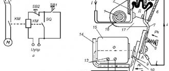
Figure 14.5 shows one of the many and varied drive control schemes. The circuit is made using two instantaneous current relays RTM and one minimum voltage relay RN , which is powered by a voltage transformer TN . CD button is used to remotely turn off the circuit breaker.
Sectioning of electrical networks is one of the means of increasing the reliability of power supply to rural consumers. Automatic switches are installed on individual outgoing lines, which, for example, in the event of a short circuit on the line, turn off the damaged section.
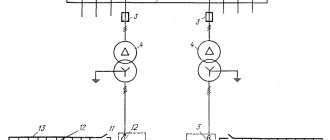
Rice. 14.6. Action diagram of automatic reclosure with separators:
1 switch at the head of the line; 2 and 3—separators on
branches; KZ - place of short circuit.
For sectioning lines with voltages of 6 and 10 kV, a three-pole network switch of the VMN-10 , controlled from the ground, with an autorecloser device. The use of automatic reclosure allows the use of simplified sectioning devices for sectioning rural electrical networks - automatic separators (AD) , made on the basis of disconnectors (Fig. 14.6). Separators 2 and 3 disconnect the corresponding sections of the line in the absence of voltage before the automatic reclosure - during the dead pause created by switch 1 at the head section of the line. Switching operation counters and a current relay are installed on the separators, and on the circuit breaker 1 of the head section there is a multiple automatic reclosure .
In the event of a short circuit (short circuit) on one of the outgoing lines, switch 1 is turned off and, under the action of the automatic reclosure mechanism, turns on again. If the short circuit is eliminated, the line remains in operation. At the moment of repeated tripping of switch 1 (if the short circuit is stable), separator 2, the pulse counter of which has recorded two short-circuit current pulses, is turned off, and the undamaged part of the line remains in operation. The separator is turned off by a spring, which is wound up when the separator is turned on manually (from the ground).
To create an artificial short circuit on the power line (to cause a shutdown of the installation) in the event of damage in the transformer of the step-down substation, short circuiters of the KZ type are intended for rated voltages of 35...220 kV.
| Next > |
Vacuum load switch disconnector RVNV-10/630 UHL1 “Vershina”
RVNV-10/630 UHL1 is the first vacuum load switch for outdoor installation developed in the Russian Federation.
To order and manufacture the RVNV-10 VERSHINA load switch, please fill out the questionnaire.
- Download the questionnaire
- Fill out the questionnaire
Main advantages:
- high switching capacity of the device;
- long service life and high reliability;
- the operations of switching on, switching off and grounding are performed sequentially with one drive handle, which eliminates the possibility of personnel error.
there is no need for maintenance or replacement of switching contacts, since there is no open arc;
Description of load switch RVNV-10/630 UHL1
RVNV-10 has a three-pole design with main contacts of a horizontal rotary type. Each pole contains two fixed insulators at the edges and one movable insulator in the center. The main contact with a rotation angle of 180° is installed on the movable insulator. On one of the fixed insulators the following are mounted: the main fixed contact and the vacuum arc extinguishing chamber in an insulating casing with an auxiliary contact. On another insulator, which is raised to the level of the main contacts, a flexible current conductor is attached to the movable contact, and grounding contacts are installed at the bottom of the insulator.
The line wires are connected to terminals on fixed insulators.
The operating position of the switch is horizontal.
The drive is a manual rotary type, has three fixed positions: on, off-wired and wired-grounded.
Operations of switching on, switching off and grounding are performed sequentially with one drive handle and operator error is eliminated. All steel parts of the switch are coated with galvanic zinc and painted. The axles are made of stainless steel. Copper contact surfaces are coated with tin.
To monitor network operating modes, automatic control and transmit telemetry data to the control center, RVNV-10 is additionally equipped (on request)
- Electric drive
- Control cabinet with uninterruptible power supply system. with an uninterruptible power supply system.
- Complex of microprocessor equipment and communications
Specifications
| Specifications | |
| Service life, years | 25 |
| Warranty period, years | 3 |
| Rated voltage, kV | 6 (10) |
| Rated current, A | 630 |
| Rated shutdown current at cosφ ≥ 0.7, A | 630 |
| Thermal resistance current, 3s, kA | 10 |
| Electrodynamic withstand current | 25 |
| Leakage distance of external insulation, cm | 35 |
| Permissible wire tension, N | 200 |
| Switching resource of operations B and O, not less | 10 000 |
| Ambient temperature | from -60°С to +40°С |
| Height above sea level | up to 1000 m |
| Ice crust thickness | up to 10 mm |
Execution options
- Load disconnector-switch RVNV-10 UHL 1
- Manual drive
- Post mounting frames
- Mounting kit
- Load disconnector-switch RVNV-10 UHL 1
- Manual drive
- Electric drive
- Control cabinet with uninterruptible power supply system.
- Communication equipment for control and data transmission to the control center
- Post mounting frames
- Mounting kit
- Load disconnector-switch RVNV-10 UHL 1
- Manual drive
- Electric drive
- Control cabinet with uninterruptible power supply system.
- A complex of microprocessor equipment and communications for monitoring network operating modes (currents, voltages), automatic control and data transmission to the control center.
- Post mounting frames
- Mounting kit
The principle of calculating the resistance of grounding conductors
There are quite a few ways to calculate the characteristics of the main grounding elements, but the main parameter for such calculations is the same - the resistance indicator. Its optimal value is determined using data from the normative regulation of the PUE. It is impossible to implement reliable protective grounding of an object without calculating the resistance of its main elements.
For example, it is necessary to determine the grounding resistance for electrical equipment with voltages over 1 kW, with an isolated neutral. In accordance with the profile data of the documentation PUE 1.7.96, it is necessary to use the formula R≤250/I, where:
- I is the indicator of the calculated grounding current;
- R is the resistance indicator of the grounding device, which should not exceed 10 Ohms.
In accordance with the PUE (1.7.104), when taking into account the regulatory information for touch current indicators (for example, 50 V is suitable), the formula is modified: R≤U/I, where U is the touch current (50 V).
Important! With an isolated neutral, as a rule, there is no need to adjust the resistance value below four ohms. However, the ideal indicator of the resistance of the grounding system is considered to be 0. The main task to which all profile calculations come down remains unchanged - to achieve the lowest possible system resistance.
In addition to making parameter calculations, an important point in grounding is the choice of device connection diagram.