The main function of the input distribution device is to receive and subsequently distribute the received electricity to individual consumers. These devices provide protection for machinery and equipment from short circuits and emergency overloads. Control devices installed in input distribution devices (IDUs) allow you to take into account the consumed electricity and monitor the correct distribution of loads in the network. Most often, ASUs are used in alternating current networks, at a voltage of 220-380 volts and a frequency of 50-60 Hz with solid grounding.
Purpose
In my opinion, Yu.V. Kharechko wrote most succinctly about the purpose of the Verkhovna Rada, as well as about its difference from it. in his book [2]:
“The input distribution device is installed at the entrance to the electrical installation of the building. The input distribution device is a special low-voltage distribution device, which is designed to perform input, metering and distribution of electricity in the electrical installation of a building. To perform these functions, the ASU is equipped with metering equipment, as well as low-voltage switching equipment and control equipment, through which the distribution and final electrical circuits emanating from the input distribution device are controlled and protected. Unlike the input device, the final electrical circuits of the building's electrical installation are connected to the ASU. »
[2]
Input distribution devices must comply with the requirements of the standards of the GOST R 51321 complex “Complete low-voltage distribution and control devices”, as well as the requirements of GOST 32396-2013.
An example of the appearance of an input distribution device with a closed (A) and open door (B) is shown in Figure 1.
Rice. 1. General view of the ASU with a closed (A) and open (B) door (based on Figure 6.12 from the book [5] by Yu.V. Kharechko)
You can find an example of such an ASU for the electrical installation of an individual residential building on the page:
How does the main switchboard work?
The main switchboard is a metal cabinet containing:
- input terminals for connecting the power line;
- output terminals for connecting the load;
- busbars or wires;
- switching devices;
- circuit breakers;
- RCD;
- energy monitoring and metering devices;
- devices for automatic switching to reserve;
- reactive power compensation devices.
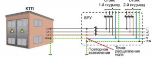
Depending on the requirements, there can be a huge number of types of main switchboards. The simplest and most universal option works like this:
- The power cable is connected to the input terminals of the panel.
- A main switch is installed between the input terminals and the distribution busbars.
- Individual consumers are connected to the busbar trunkings through separate circuit breakers. In this case, the ratings of the machines must correspond to the load power.
- When the main switch is turned on, the busbars are energized; with the help of circuit breakers, power can be switched for each consumer separately.
Note! A malfunction of one of the consumers will trigger the corresponding circuit breaker, so the rest of the load will be provided with power regardless of the state of the faulty part.
Composition of the Verkhovna Rada
Kharechko Yu.V. in his book [2] he described in great detail what functional blocks and panels an ASU can consist of. Here are the relevant quotes from his book:
“Input distribution devices consist of functional blocks, which are understood as a set of interconnected equipment installed in the ASU, which ensures the performance of certain functions. In a multi-panel ASU, the functional block can be made in the form of a panel that provides a specific function. »
[2]
Input distribution devices can have the following functional blocks [2]:
- input block through which electricity is supplied to the ASU. This functional block contains switching and protective equipment, and also includes part of the ASU volume necessary for placing, fastening and connecting the supply network (circuit) conductors to the equipment;
- an automatic backup power supply unit (ABP), containing monitoring and control equipment for the switching equipment of the input unit, to which backup power supplies are connected;
- an electricity metering unit containing a direct or transformer-connected electricity meter, current transformers and a test adapter box;
- distribution block containing switching and protective equipment of distribution and final electrical circuits. This block also includes part of the ASU volume or panel for placing and connecting conductors;
- an automatic lighting control unit containing switching and protective equipment for the final electrical circuits of general house lighting and control equipment for these circuits.
Multi-panel input and distribution devices consist of panels, which are detachable parts of a multi-panel ASU, made on a single structural basis with other panels and containing corresponding functional blocks.
Input distribution devices may have the following panels [2]:
- an input panel containing switching and protective equipment, as well as control equipment for input and electricity metering units;
- input panel with ATS, which is an input panel equipped with an ATS unit;
- a distribution panel containing equipment for distribution units, which can also house electricity metering units, automatic or non-automatic lighting control units, etc.;
- fire-fighting device panel, which is a distribution panel that is attached to the input panel with automatic transfer switch and is designed to power electrical equipment and control circuits of fire extinguishing equipment, alarm circuits of fire-fighting devices, evacuation lighting and other electrical receivers necessary for warning and extinguishing a fire.
Installation of switchgear
The decoding of the switchgear itself indicates that the installations are immediately produced in kits, and they do not need to be assembled from disparate elements. The manufacture of switchgear is carried out at a specialized enterprise. Complete switchgears are delivered to the location in the form of solid cabinets or enlarged blocks (3-5 chambers assembled together), completely ready for installation. Recently, mixed switchgear, consisting partly of prefabricated and complete elements, has been widely used.
The installation process consists of several sequential activities:
- Preparing the foundation.
- Assembly of structures for lighting points of free-standing protective panels and electrical devices.
- Preparation of the internal grounding network and general lighting network of the switchgear.
- Placement of switchgear units. Each cell is installed in a specific place according to the plan. Installation begins with the outermost element. The individual blocks are connected to each other by attaching the side walls to each other.
After completion of installation work, it is mandatory to check the oil level in the tanks of the switches, the correct operation of all main and auxiliary elements and blocking devices. The entire process must be carried out in accordance with the manufacturer’s instructions attached to the equipment.
After making sure that the entire device is assembled correctly (particular attention is paid to ensuring that the cells are not located at an angle), high-voltage cable lines are brought to the terminals on the rear door of the switchgear and secured with end sleeves.
ASU classification
Input distribution devices are divided into [2]:
- multi-panel ASUs, in which the functional blocks are made in several panels;
- single-panel ASUs, made on the same structural basis as multi-panel ASUs, and containing all the necessary functional blocks; cabinet ASUs containing all the necessary functional units installed in a cabinet-type shell.
Depending on the type of installation, cabinet ASUs can be floor-mounted, wall-mounted, or built into a niche.
Kharechko Yu.V. in his book [2] focuses on the fact that:
“According to the classification of low-voltage switchgear given in GOST R 51321.1-2007, there may be box switchgear designed for installation on a vertical plane. Therefore, input distribution devices that are installed on walls, for example, in electrical installations of individual residential buildings, should be called box ASUs, and not cabinet ASUs. »
[2]
Requirements
Input and distribution devices can be designed as electrical equipment of class I or class II.
“Class I ASU structural elements related to frames, shells and other conductive parts should be made primarily of steel with a protective coating. »
clause 6.2.1 [3]
“ Class II ASU shells, if they do not serve as supporting elements for live parts, must be made of insulating materials that are resistant to ignition when exposed to wire heated to a temperature of (850 ± 10) ° C, when the ASU is built into low-flammable walls - up to ( 650±10)°С (according to GOST IEC 60439-3). »
clause 6.2.2 [3]
Kharechko Yu.V. the requirements of paragraphs 6.6 and 6.2.19 of GOST 32396-2013 were formulated as follows [2]:
“The design of the input distribution device must provide one-way service from the front side. Controls for switching equipment and control equipment are located behind the doors of the ASU. Input and distribution devices that are installed in electrical rooms are usually made with a degree of protection of at least IP2X on the front and sides and IP00 on the top, bottom and rear. ASUs installed outside electrical rooms must have a degree of protection (with doors closed) of at least IP31 on all sides, except for the lower base adjacent to the floor. The degree of protection provided by the operational panel when the ASU doors are open must be at least IP2X. In a cabinet-type input distribution device of class I, the operating panel can be made of conductive or insulating material, and in a class II ASU - only of insulating material. »
[2]
Kharechko Yu.V. in his dictionary [2] formulated the requirements of clauses 6.2.8, 6.2.9 and 6.2.14 from [3] as follows:
“ASU input and distribution blocks must have sufficient volume to accommodate conductors and connect conductors to switching and control equipment, to busbars and terminal blocks, which is carried out in compliance with the standardized bending radii of insulated wires and cable cores. These blocks must have elements for fastening wires and cables. Surge protection devices are also installed in the ASU input blocks, which are connected after the input protective equipment. »
[2]
Based on clauses 6.2.15, 6.2.17 from [3] Kharechko Yu.V. formulated the following requirements [2]:
“In single-panel ASUs and input panels of multi-panel ASUs, special compartments with doors should be provided to accommodate electricity metering units. The doors must be locked with a key and have elements for sealing them. In a cabinet-type ASU, the input terminals for the conductors of the power supply network and the metering circuit should be located behind the operating panel, which should be equipped with elements for sealing, while the metering units may not be separated into separate compartments. »
[2]
According to clause 6.2.29 of GOST 32396-2013:
“To take meter readings, the doors of the compartments or the doors of single- and multi-panel ASUs must have windows covered with impact-resistant transparent material. Such windows can also be provided in the doors of cabinet-type ASUs. It is allowed not to install windows for taking meter readings in ASUs installed in electrical rooms. »
[3]
The cross-sections of the phase busbars of the ASU are selected depending on the values of the rated currents of the input equipment given in Table 2 of GOST 32396-2013, taking into account their permissible heating.
The cross-sections of the protective bus PE and the neutral bus N are taken depending on the cross-section of the phase buses in accordance with the requirements of tables 3 and 4 of GOST 32396-2013 [3]. Table 3 - Sections of phase and corresponding protective conductors PE, mm2 (based on GOST 32396-2013)
| Phase conductor cross-section S, mm2 | Cross-section of the corresponding protective conductor, mm2 | |
| S ≤ 16 | S | |
| 16 < S ≤ 35 | 16 | |
| 35 < S ≤ 400 | S/2 | |
| 400 < S ≤ 800 | 200 | |
| Note – If the material of the protective conductor differs from the phase conductor, then its cross-section must be such that it provides conductivity equivalent to the conductivity of the corresponding cross-section of the conductor given in the table. | ||
Table 4 - Cross-sections of phase and corresponding neutral conductors N, mm2 (based on GOST 32396-2013)
| Phase conductor cross-section S, mm2 | Cross section of the corresponding neutral conductor, mm2 | |
| three-phase circuits | single-phase circuits | |
| S ≤ 16 | S | S |
| S>16 | S/2 | S |
“ASU busbars are equipped with special clamps, through which dismountable connections of phase, neutral and protective conductors are made. The number of clamps on the busbars and their cross-sections must correspond to the number of conductors of external and internal electrical circuits connected to them and their cross-sections. Busbars must withstand electrodynamic and thermal effects caused by short-circuit currents. »
[2]
“Input distribution devices must be provided with clamps designed for connecting conductors of external electrical circuits and having means for stabilizing contact pressure. As a rule, one conductor must be connected to each protective or neutral conductor terminal. In Class I ASUs, the terminals for neutral conductors must be insulated from their conductive shells in the same way as the terminals for phase conductors, and the terminals for protective conductors must have electrical connections to the shells. In Class II ASUs, the terminals for protective and neutral conductors must be insulated from their conductive shells in the same way as the terminals for phase conductors. »
[2]
“Exposed conductive parts of class I input distribution devices must be reliably connected to each other and connected to their protective busbars. The resistance between the protective bus and each open conductive part of the ASU should be no more than 0.1 Ohm. »
[2]
“The internal electrical circuits of the ASU should be made with insulated copper wires. Busbars, as a rule, should be copper. Aluminum busbars can be used, with the exception of PE protective busbars, which can be made of coated steel. In this case, the conductivity of the steel busbars must match the conductivity of the copper busbars. »
[2]
“Wires of internal electrical circuits, having small cross-sections, are usually laid in input distribution devices in bundles or placed in boxes. The number of wires combined into a bundle or laid in a box is determined by the conditions of their permissible heating when electric currents flow through them equal to the rated currents of the equipment to which they are connected. The insulation resistance of the internal circuits of the ASU in a cold state must be at least 10 MOhm. »
[2]
According to paragraph 6.8.1 from [3]:
“At rated currents of cabinet-type and single-panel ASUs, as well as at rated currents of multi-panel ASU panels, the temperature of their parts exceeds the ambient temperature and the permissible heating temperature of these parts at an ambient temperature of 35 °C should not exceed the values given in Table 5 of GOST 32396-2013. »
[3]
Table 5 - Temperature rise, °C (based on GOST 32396-2013)
| Part of the ASU | Permissible temperature rise above ambient temperature 35 °C1) | Permissible heating temperature, °C |
| Contact connections of equipment terminals, contact clamps with internal and external conductors | 55 | 90 |
| Bare conductors (busbars) | 55 | 90 |
| PVC insulated conductors | 35 | 702) |
| Insulating material controls | 20 | 55 |
| Accessible parts of the shell: – metal – made of insulating material | 20 55 | 55 60 |
| 1) At an upper ambient temperature value other than 35 °C, the permissible temperature rises can be changed within the limits of the specified permissible heating temperatures. 2) The permissible heating temperature of conductors with other types of insulation is established in the technical specifications for specific types of ASUs. | ||
According to clause 6.9.1 from [3]:
“Metal parts of the ASU must have protective paint, polymer powder and (or) metal coatings. »
[3]
GOST 32396-2013 (clause 6.10.2) established the service life of input distribution devices equal to 25 years. During this period, replacement of individual components of the ASU is allowed.
Requirements for color and alphanumeric marking of conductors in ASU.
Marking of conductors in input distribution devices should be carried out in accordance with the requirements of GOST 33542-2015 (IEC 60445:2010) [4], which established general rules for the use of certain colors and alphanumeric designations to identify conductors in order to ensure safety during the operation of electrical equipment and electrical installations . The colors and alphanumeric designations of conductors established in GOST 33542-2015 are intended for use in cable products, buses, electrical equipment and electrical installations.
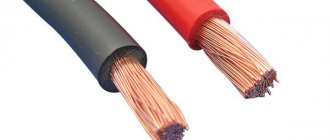
Protective conductors PE should be green-yellow, and neutral conductors N should be blue.
The requirements of GOST 33542-2015 prohibit the use of yellow and green colors separately for marking conductors. Yellow and green are also prohibited from being used in any two-color combination other than the yellow-green color combination.
Protective and neutral buses must be designated PE and N, respectively. Wires of internal electrical circuits must have digital markings at the ends in accordance with the circuit diagrams of the ASU. At the ends of the prefabricated phase busbars, unless otherwise indicated on the circuit diagrams, the signs L1, L2, L3 should be applied.
Phase conductors in single-phase electrical circuits should be identified in brown, in three-phase electrical circuits - brown, black and gray. The alphanumeric identification of the phase conductor of a single-phase electrical circuit should be “L”, the phase conductors of a three-phase electrical circuit should be “L1”, “L2” and “L3”.
If a single-phase electrical circuit is a branch of a three-phase electrical circuit, the color and alphanumeric identification of the phase conductor of the single-phase electrical circuit must match the color and alphanumeric identification of the phase conductor of the three-phase electrical circuit with which it has an electrical connection.