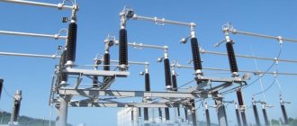
Rigid busbar of substations
In Russia, busbars are traditionally carried out using ordinary steel-aluminum wire and fittings designed for overhead power lines are used.
But the tasks and approaches to solving these problems for overhead power lines and substations are different. In particular, modern requirements for the compactness of substations cannot be satisfied with wire busbars. An alternative solution is a rigid busbar, made on the basis of aluminum pipes of a special alloy. The diameters of the pipes are selected based on the current loads of the bus. Until now, the use of such rigid busbars has been limited in Russia due to the lack of a domestic supplier of special busbar supports and special fittings for connecting busbars and their branches from round pipes. Over the past three years, CJSC "Reinforcing and Insulating Plant" (Lytkarino) has been developing and mastering a range of products for rigid busbars of substations. During this time, more than a dozen products were developed and introduced that had not previously been produced in Russia. The combination of specially designed busbar supports, busbars and fittings represents a comprehensive solution for substation busbars. The plant has developed and put into production a large list of not only busbar supports, but also rigid busbar fittings. Modern solutions in high-voltage insulation were used for busbar supports. Busbar supports are made on the basis of polymer rod insulators, taking into account the specific operation of the insulator as part of a busbar support.
Research conducted by specialists has revealed the need to consider a busbar support not just as an insulator and a busbar holder, but as an integrated structure, taking into account their joint work, taking into account the frequency of vibration, short circuit currents, etc. The busbar supports use cast busbar holders made of a special alloy. All this allows us to talk about a complex system of rigid tubular busbars installed on high-voltage equipment in switchgears.
The use of cast prefabricated busbar supports and connecting fittings for rigid busbars provides a number of advantages compared to the welded version. In the new version of the busbar, thanks to the abandonment of welding, it became possible to use a pipe made of 1915T alloy, which has higher electrical conductivity, mechanical strength and corrosion resistance, as a tire. Previously this was impossible due to the poor weldability of this composition.
The improved electrically conductive properties of the new version of the busbar make it possible to increase the throughput and other electrical characteristics of the busbar with the same material consumption. In addition, by changing the geometric dimensions, the loads from climatic influences on the busbar are reduced, and with them the loads on the support insulators and disconnector terminals. The contact surfaces of cast busbar holders have an additional coating that improves electrical contact.
In addition, in places where the surfaces of conductive parts come into contact, the use of electrically conductive lubricant according to EPOS-150, EPOS-250 is provided. Lubricants are specially designed to reduce and stabilize electrical resistance in metal bolted, contact joints of rigid busbar reinforcement and its connection to power equipment. The lubricant can reduce electrical resistance up to a hundred times and stabilize electrical resistance for ten years.
1915T aluminum alloy pipes, which have high strength, corrosion resistance and good weldability, are used as rigid busbars.
Rigid busbars provide quick and high-quality installation, the necessary compensation for linear temperature deformations of tires and minor errors when installing bus supports.
Current compensators guarantee high quality electrical connections. They act as screens, eliminating the possibility of corona discharges and radio interference.
The use of detachable bolted contacts on rigid busbars made it possible to unify sets of rigid busbars and significantly facilitate installation when making various branches with flexible connections, including bundles of wires.
Rigid busbar sets of high factory readiness allow you to reduce the costs of constructing an outdoor switchgear: metal consumption is reduced on average by 10-15 percent, reinforced concrete consumption - by 10-20 percent, structure area - by 10-15 percent, the volume of construction and installation work and labor costs - by 25 percent depending on the electrical connection diagrams of the outdoor switchgear and specific operating conditions in the construction areas.
The rigid busbar is equipped with hollow aluminum pipes class 1915T or an analogue of the E-AlMgSi0.5 series alloy in accordance with DIN EN 573-3, with a damper cable, busbar supports with a breaking load from 12.5 to 20 kN, units for direct fastening of tires to equipment, construction metal structures for supporting insulation, runs of flexible busbars from rigid busbars to equipment and fittings for fastening flexible busbars to equipment. Rigid tires are designed to work at altitudes above sea level up to 1000 meters. Type of climatic modification and placement category - UHL1 according to GOST 15150. Seismic resistance of rigid busbars - up to 9 points on the MSK 64 scale (acceleration in horizontal directions 0.36 g; in vertical direction 0.25 g).
The ZhOS is designed using the block method, that is, depending on the nature of the site and the layout of the 110-500 kV outdoor switchgear, the distance between the axes of the supports in the span for the rigid busbar pipe is determined individually with any cell pitch, which determines the flexibility of the technical solutions included in the project. The layout of substations with ZhOS allows to significantly reduce the area under the switchgear and make the project economically profitable, taking into account the reduction in the cost of materials and the labor intensity of the switchgear construction.
We invite all design organizations to cooperate. We will provide complete equipment catalogs and typical substation diagrams in AutoCAD format. We are ready to develop new types of reinforcement and rigid busbar supports, provide advice, and share experience. We will be glad to have any contacts in this area, which is new for Russia.
Definitions of busbars and connecting busbars?
To post a reply you must log in or register.
Messages 10
1 Topic from RTF 2012-01-03 20:11:34
- RTF
- User
- Inactive
- Registered: 2011-01-08
- Messages: 38
- Reputation: [ 0 | 0 ]
Topic: Definitions of busbars and connecting busbars?
Are there definitions of “busbars” and “connecting busbars”? Tell me, who knows where I can read them. My searches yielded no results. Thank you.
2 Reply from SAA 2012-01-03 21:34:59
- SAA
- no longer a relay protection operator
- Inactive
- From: Kharkov
- Registered: 2011-01-11
- Messages: 235
- Reputation: [ 0 | 0 ]
Re: Definitions of busbars and connecting busbars?
prefabricated, yes, but I haven’t heard of connecting ones. There is a bus connecting switch - ShSV. initially there is a busbar system, which can be sectioned and can be single or double. I think doro can suggest a more precise name for the dispatcher - he is in closer communication with the dispatchers
3 Reply from Windtalker315 2012-01-04 07:45:23
- Windtalker315
- User
- Inactive
- Registered: 2011-11-04
- Messages: 618
- Reputation: [ 1 | 0 ]
Re: Definitions of busbars and connecting busbars?
I agree with the previous author. The term busbar connection system does not exist. Equipment busbars come closest to this concept - they are just “connecting”
Air circuit breaker
From Wikipedia - the free encyclopedia
Air circuit breaker
(
power circuit breaker
,
circuit breaker
) is an electrical device that is capable of switching on, conducting and switching off electric current. Automatic shutdown of the electrical circuit occurs during overloads and short circuits. Switching off overload and short circuit currents by a circuit breaker must be carried out in accordance with the specified time-current characteristics.
Modern circuit breaker (automatic)
must meet, first of all, two requirements: reliably protect electrical receivers in emergency modes from short circuits and overloads, and also be convenient and safe to use throughout their entire service life. These requirements also take into account the specific application of an individual switch, such as switching frequency, increased requirements for vibration resistance, free spatial position, aggressive external environment that accelerates metal corrosion, as well as the influence of ambient temperature and humidity.
Reliable operation of the circuit breaker to prevent short circuits and overloads increases the service life of electrical receivers by limiting thermal and electrodynamic effects on them, and also prevents technological losses that can be caused by an interruption in power supply, which, in turn, can cause indirect damage, including reputational.
Encyclopedic YouTube
Subtitles
Content
- 1 Standards
- 2 Classification of circuit breakers 2.1 Types of circuit breaker designs
- 2.2 Placement of circuit breakers
- 2.3 Principles of arc extinction
- 3.1 Requirements of switchboard manufacturers
- 4.1 Working in tropical climates
Standards
In Russia, switches must comply with GOST R 50345-2010, GOST IEC 60898-2-2011, GOST R 50030.2-2010 and the Technical Regulations on Fire Safety Requirements Federal Law No. 123 dated July 22, 2008. In Europe, definitions and requirements for switches are described in the standard IEC 60947-1 and IEC 60947-2 (VDE 0660). In Japan the standard is JIS C 8201-2-1, in the USA the standard is ANSI C37.13. In accordance with Russian requirements, the following requirements are also imposed on machines:
- The current-carrying circuit of the machine must pass the rated current for an arbitrarily long time.
- The machine must provide repeated shutdown of maximum short-circuit currents reaching hundreds of kiloamperes. After disconnecting these currents, the circuit breaker must be suitable for continuous transmission of the rated current.
- To ensure the electrodynamic and thermal stability of electrical installations, reduce destruction and other consequences caused by short-circuit currents, circuit breakers must have a short shutdown time.
- In order to reduce the overall dimensions of low-voltage complete devices (LVDs) and increase service safety, a minimum exhaust area of heated and ionized gases during the arc extinguishing process is required. It is also necessary to reduce the overall dimensions of the switch itself.
- The circuit breaker protection elements (electronic release) must provide the necessary currents, operating times and selectivity; for this purpose they have adjustment of the current and operating time.
vote
Article rating
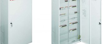
Structure of the OZhKCH type symbol
| OJCC | — | XXX | — | XXX | / | XXXX | — | XX | XX |
| 1 | 2 | 3 | 4 | 5 | 6 |
1 – complete rigid busbar manufactured by JSC “ChEMZ”; 2 – voltage class, kV; 3 – thermal resistance current of tires for 3 s, kA; 4 – rated current of the busbar, A; 5 – number of the main circuit diagram; 6 – climatic modification and placement category according to GOST 15150 and GOST 15543.1.
Additional parameters are indicated in the questionnaire.
An example of recording the symbol for a busbar type OZhKCh voltage class 110 kV, for thermal current - 40 kA, for rated current - 2000 A, circuit number - 5 AN, climatic version and placement - UHL1: OZHKCH-110-40/2000-5AN UHL1
Technical parameters and characteristics of the busbar
The main technical parameters and characteristics of the OGCI must correspond to the parameters specified in the table.
| No. | Name of parameters | Parameter meaning from execution | |||
| OJCH-6 | OZhKCH-10 | OZHKCH-35 | OZHKCH-110 | ||
| 1 | Rated voltage, kV | 6 | 10 | 35 | 110 |
| 2 | Highest operating voltage (linear), kV | 7,2 | 12 | 40,5 | 126 |
| 3 | Rated frequency, Hz | 50 | |||
| 4 | Rated current, A | 2000 | |||
| 5 | Tire thermal resistance current, kA | 40,0 | |||
| 6 | Thermal resistance current flow time, s | 3 | |||
| 7 | The highest peak of the rated short-term withstand current of the busbar (electrodynamic withstand current), kA | 102 | |||
| 8 | Insulation level according to GOST 1516.3-96 | Normal | |||
| 9 | Electrical insulation strength: - test voltage of the full lightning impulse relative to the ground, kV - short-term (one-minute) alternating voltage relative to the ground and between phases, kV - in a dry state - in the rain | 60 32 20 | 75 42 28 | 190 95 80 | 450 200 200 |
| 10 | Maximum wind speed, m/s | 32 | |||
| 11 | Maximum wind speed during ice conditions, m/s | 16 | |||
| 12 | Permissible ice crust thickness, mm | 20 | |||
The OZHKCH is designed to operate in conditions corresponding to the climatic modifications of the UHL location category 1 according to GOST 15150-69 and GOST 15543.1-89, while:
- the lower operating limit value of the ambient air temperature is taken to be minus 60 C;
- the upper limit value of the ambient temperature is +40 C.
- environment - atmosphere type II* according to GOST 15150;
- the environment is not explosive or fire hazardous, does not contain dust in concentrations that reduce the parameters of the product, and is not exposed to gases, vapors and chemical deposits.
The OZhKCH is designed to operate at altitudes above sea level up to 1000 m.
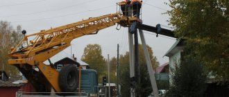
Selection of wheels and tires at the substation
When installing single-pitch and dual-pitch tires, the load-carrying capacity and cross-country ability of the unit can be maintained in case of increased ground clearance. This can be done with a more pronounced tread for off-road driving.
When using high-profile wheels, the technical parameters of trucks are improved:
- the large diameter of single- and double-slope cargo wheels increases ground clearance by 15-20 cm;
- the angle limiting overcoming obstacles increases to 49 degrees;
- the angle increases, which ensures cross-country ability and affects the central part of the chassis;
- traction qualities are improved - the tire allows you to increase the coefficient of adhesion to any surface.
In the case of single or double tires, in addition to replacing a set of tires, you also need to change the wheel rims. Kits with improved wear resistance and load capacity are installed at the substation.