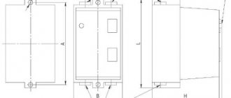
Design
RG series disconnectors for voltages of 110 and 220 kV with a normal insulation level in accordance with GOST 1516.3, as well as disconnectors with increased electrical strength, are made with improved performance properties. The connecting dimensions of the new disconnectors were selected taking into account the possibility of installing them on existing supporting structures of disconnectors of the RDZ series.
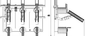
Disconnectors are two-column devices with contact blades rotating in a horizontal plane. Disconnectors consist of a main current-carrying system, rotary support insulation, a supporting frame and grounding conductors.
The contact blades of the disconnectors are made of copper bars (110 kV) or pipes (220 kV), to which bronze alloy lamellas are attached. The output contacts are made with transition contact rollers and are hermetically sealed. This ensures stable contact pressure throughout the entire service life and low operating forces on the manual drive handle. The contact surfaces of the detachable and output contacts are coated with silver.
The disconnectors are equipped with high-strength porcelain or polymer insulators.
The main contact blades of disconnectors and grounding switches can be controlled by both electric motor drives PD-14UHL1 and manual drives PRG-6UHL1. PD-14UHL1 drives are equipped with switching units based on microswitches. All drives are equipped with a modernized electromagnetic locking type ZB-1M with an electromagnetic key KEZ-1M and a key KM-1 for emergency release.
Disconnectors and their main components are protected by Russian Federation certificates for utility models.
Purpose and where to use
The use of disconnectors in the energy sector to break circuits is dictated, first of all, by safety considerations. They are used to make connections to contact networks for supplying current from supply lines. These mechanisms also serve to safely change the interconnection patterns of circuit sections.
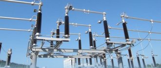
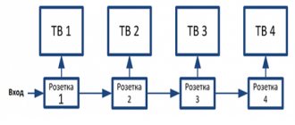
Figure 1 shows a section of a line with high-voltage disconnecting devices.
Figure 1. Line section with high-voltage disconnectors
The switching mechanisms under consideration have two important qualities that allow you to control the switching process:
- The ability to visually monitor the position of moving contacts at disconnection points.
- The absence of a mechanism allowing the possibility of free (arbitrary) release. The use of manual drives ensures that the specialist performs the planned operation of de-energizing or connecting the electrical network at the right time.
This design of the disconnector allows maintenance personnel to quickly assess the condition of the working parts of the switching mechanism before switching on, as well as visually monitor the position of the contact knives in a specific situation. Disconnectors always operate using high voltage switches, both outdoors and indoors.
Such devices can be used to switch transformers operating at no-load, as well as to disconnect lines with circulating pickup currents. With appropriate shunting devices, it is possible to disconnect live electrical circuits or turn off low-power transformer load currents. In this case, an arc discharge is always observed at the initial stage of shutdown or before switching on, when the contacts approach the breakdown distance.
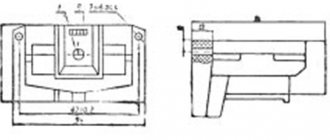
The arcing time is reduced by the presence of contact springs. An exception is the class of load switches, the design of which includes autogas arc extinguishing devices - VNA. Such switches can be used as high-voltage disconnectors, which are used for switching sections of circuits up to 10 kV. (Fig. 2).
Figure 2. High-voltage load switch VNA
Main Applications
High voltage circuit disconnectors are used in many applications. With their help they serve:
- networks of complete transformer substations, including mobile transformer substations;
- family of complete switchgears KRU and KRUN;
- capacitor units;
- prefabricated chambers designed for one-sided maintenance;
- Main switchboards, input and distribution cabinets and other equipment.
The ability of three-pole and single-pole disconnectors to switch charging currents of overhead wires and cable lines, turn on and off induction currents of power transformers, cut off equalizing currents, and disconnect circuits with small load currents makes these devices indispensable in various power systems.
The areas of application of high-voltage disconnectors are regulated by PTEEP. The rules allow their use in networks of 6 - 10 kV, to switch on or off load currents up to 15 A or equalizing currents up to 70 A.
Symbol
for voltage 110 kV
RGNP.Х1Х2- Х3-110.II/ Х4-Х5УХЛХ1
- P – disconnector;
- G – horizontal rotary type;
- N – insulation level according to GOST 1516.3-96 (in the reinforced version the index is not affixed);
- P – with polymer insulation (in the version with porcelain insulation there is no index);
- B – vertical installation;
- X1 – number of grounding conductors (1 or 2);
- X2 - location of grounding conductors relative to the driving and driven columns: a - from the side of the driving column, b - from the side of the driven column;
- X3 – type of installation (K – for keel installation, SK – for step-keel installation, V – for installation on a vertical plane, OP – for single-pole installation);
- 110 - rated voltage, kV;
- II - degree of insulation contamination according to GOST 9920-89 (in version I the index is not affixed);
- X4 – rated current (1000, 1600, 2000 or 3150), A;
- X5 - rated short-term withstand current with increased resistance to short-circuit currents. 40, 50, 63 kA (in the normal version the parameter is not specified);
- UHL – climatic version according to GOST 15150-69;
- 1 — placement category according to GOST 15150-69
for voltage 150, 220 kV
RGNP.-Х1 -Х2Х3- Х4.II/ Х5-Х6УХЛХ1
- P – disconnector;
- G – horizontal rotary type;
- N – insulation level according to GOST 1516.3-96 (in the reinforced version the index is not affixed);
- P – with polymer insulation (in the version with porcelain insulation there is no index);
- X1 – installation type (K – for keel installation)
- X2 – number of grounding conductors (1 or 2);
- X3 - location of grounding conductors relative to the driving and driven columns: a - from the side of the driving column, b - from the side of the driven column;
- X3 – type of installation (K – for keel installation, SK – for step-keel installation, V – for installation on a vertical plane, OP – for single-pole installation);
- X4 - rated voltage 150 or 220 kV;
- II - degree of insulation contamination according to GOST 9920-89 (in version I the index is not affixed);
- X5 – rated current (1000, 2000 or 3150), A;
- X6 - rated short-term withstand current with increased resistance to short-circuit currents. 40, 50, 63 kA (in the normal version the parameter is not specified);
- UHL – climatic version according to GOST 15150-69;
- 1 — placement category according to GOST 15150-69
Classification
The domestic industry produces high-voltage disconnectors of various types. They can be classified according to the following criteria:
- by number of poles;
- type of contact knife (rotary, chopping, swinging);
- installation location (open space or room);
- by control method: manual (using an insulating rod or levers), electromechanical, hydraulic, pneumatic.
In addition, devices differ in rated voltage and rated current for which they are designed. Products come with grounding switches (disconnectors RVZ, Fig. 4), with figured knives (RVF) and others.
Figure 4. RVFz 1063
The type of device can be determined by its designation.
The letters indicate:
- P – type of product, in this case a disconnector;
- N – external;
- G – horizontal installation;
- L – linear;
- Z – disconnector with grounding blades. The numbers 1, 2... indicate the number of grounding conductors;
- D – with two support-insulating columns;
- The numbers 10, 35, 110, 220 mean the rated voltage in kilovolts.
For example, RV is an internal disconnector, and the abbreviation RLND means that this is a linear type of device with two support-insulating columns for outdoor use.
Advantages
RG series disconnectors for voltages of 110 and 220 kV have the following advantages compared to previously produced disconnectors:
- The insulation of the DG disconnectors can withstand higher lightning impulse test voltages relative to ground and between poles, so it can also be used in high mountain areas.
- The contacts of the main knives and grounding switches are made using contact rods made of bronze alloy, which eliminates the need for springs and does not require adjustment of the contact pressure during operation throughout the entire service life.
- Output contacts are sliding type (instead of flexible connections) with rotation on closed ball bearings with long-term lubrication embedded in them for the entire service life and with hermetically sealed bearings and contacts.
- The bases of the rotary columns are equipped with sealed ball bearings with long-term lubrication embedded in them and do not require additional lubrication during the entire service life.
- The rod and shaft joints have low-friction polymer inserts and are therefore maintenance-free.
- The rigidity of the plinths has been increased.
- The possibility of stepless adjustment of the tilt of the rotary bases with insulators is provided for setting the approach of the contact knives in detachable contacts.
- Low torques on the drive handles during operation and stable throughout the entire service life.
- The disconnectors are operational in ice conditions up to 20 mm, whereas previously produced disconnectors allowed operation with a crust thickness of up to 10 mm.
- All steel parts of the disconnectors have durable anti-corrosion coatings with hot and thermal diffusion zinc. The contact system is made of copper coated with silver and tin.
- The delivery kits include connecting elements between the poles, between the disconnector and the drive, which are joined during installation without welding.
- Disconnectors are supplied in larger units (more complete factory readiness) and, as a result, have lower installation costs.
- The delivery set includes a bracket for installing drives, attached to the disconnector base.
| Product name and type | Purpose, brief technical characteristics | Designation TU | Year of production | |||
| Thermal resistance current, kA | Limit through current, kA | Weight, kg | Accessory drive, type | |||
| RG-110/1000 UHL1 | 31,5 | 80 | 248 | PRG-6UHL1 or PD-14UHL1 | TU 3414-028- -41586029-98 | 1999 |
| RG-110.II/1000 UHL1 | 31,5 | 80 | 263 | — // — | — // — | — // — |
| RG-K-110/1000 UHL1 | 31,5 | 80 | 248 | — // — | — // — | — // — |
| RG-K-110.II/1000 UHL1 | 31,5 | 80 | 263 | — // — | — // — | — // — |
| RG-OP-110/1000 UHL1 | 31,5 | 80 | 235,5 | — // — | — // — | — // — |
| RG-OP-110.II/1000 UHL1 | 31,5 | 80 | 251,5 | — // — | — // — | — // — |
| RGP-110/1000 UHL1 | 31,5 | 80 | 198 | — // — | — // — | — // — |
| RGP-K-110/1000 UHL1 | 31,5 | 80 | 209 | — // — | — // — | — // — |
| RGP-OP-110/1000 UHL1 | 31,5 | 80 | 197 | — // — | — // — | 2001 |
| RGN-110/1000 UHL1 | 31,5 | 80 | 198 | — // — | — // — | 2000 |
| RGN-110.II/1000 UHL1 | 31,5 | 80 | 216 | — // — | — // — | — // — |
| RGN-K-110/1000 UHL1 | 31,5 | 80 | 235 | — // — | — // — | — // — |
| RGN-K-110.II/1000 UHL1 | 31,5 | 80 | 253 | — // — | — // — | — // — |
| RGN-SK-110/1000 UHL1 | 31,5 | 80 | 222 | — // — | — // — | 2002 |
| RGN-SK-110.II/1000 UHL1 | 31,5 | 80 | 240 | — // — | — // — | — // — |
| RGN-V-110/1000 UHL2 | 31,5 | 80 | 182 | — // — | — // — | — // — |
| RGN-V-110.II/1000 UHL2 | 31,5 | 80 | 200 | — // — | — // — | — // — |
| RGN-OP-110/1000 UHL1 | 31,5 | 80 | 220 | — // — | — // — | 2002 |
| RGN-OP-110.II/1000 UHL1 | 31,5 | 80 | 238 | — // — | — // — | — // — |
| RGNP-110/1000 UHL1 | 31,5 | 80 | 162 | — // — | — // — | 2000 |
| RGNP-K-110/1000 UHL1 | 31,5 | 80 | 231 | — // — | — // — | 2002 |
| RGNP-SK-110/1000 UHL1 | 31,5 | 80 | 218 | — // — | — // — | — // — |
| RGNP-OP-110/1000 UHL1 | 31,5 | 80 | 216 | — // — | — // — | — // — |
| RG-110/2000 UHL1 | 40 | 100 | 295 | — // — | 1999 | |
| RG-110.II/2000 UHL1 | 40 | 100 | 319 | — // — | — // — | — // — |
| RG-OP-110/2000 UHL1 | 40 | 100 | 280 | — // — | — // — | — // — |
| RG-OP-110.II/2000 UHL1 | 40 | 100 | 304 | — // — | — // — | — // — |
| RGN-110/2000 UHL1 | 40 | 100 | 224 | — // — | — // — | 2002 |
| RGN-110.II/2000 UHL1 | 40 | 100 | 230 | — // — | — // — | 2000 |
| RGP-110/2000 UHL1 | 40 | 100 | 212 | — // — | — // — | 2001 |
| RGP-OP-110/2000 UHL1 | 40 | 100 | 224 | — // — | — // — | — // — |
| RGN-K-110/2000 UHL1 | 40 | 100 | 264 | — // — | — // — | 2002 |
| RGN-K-110.II/2000 UHL1 | 40 | 100 | 282 | — // — | — // — | — // — |
| RGN-SK-110/2000 UHL1 | 40 | 100 | 250 | — // — | — // — | — // — |
| RGN-SK-110.II/2000 UHL1 | 40 | 100 | 268 | — // — | — // — | — // — |
| RGN-OP-110/2000 UHL1 | 40 | 100 | 248 | — // — | — // — | — // — |
| RGN-OP-110.II/2000 UHL1 | 40 | 100 | 266 | — // — | — // — | — // — |
| RGNP-110/2000 UHL1 | 40 | 100 | 178 | — // — | — // — | 2000 |
| RGNP-SK-110/2000 UHL1 | 40 | 100 | 246 | — // — | — // — | 2002 |
| RGNP-OP-110/2000 UHL1 | 40 | 100 | 304 | — // — | — // — | — // — |
| RG-110/2000-50 UHL1 | 50* | 125* | 287 | — // — | 2007 | |
| RG-110.II/2000-50 UHL1 | 50* | 125* | 311 | — // — | — // — | — // — |
| RG-OP-110/2000-50 UHL1 | 50* | 125* | 272 | — // — | — // — | — // — |
| RG-OP-110.II/2000-50 UHL1 | 50* | 125* | 296 | — // — | — // — | — // — |
| RGP-110/2000-50 UHL1 | 50* | 125* | 216 | — // — | — // — | — // — |
| RGP-OP-110/2000-50 UHL1 | 50* | 125* | 216 | — // — | — // — | — // — |
| RGN-110/2000-50 UHL1 | 50* | 125* | 216 | — // — | — // — | — // — |
| RGN-110.II/2000-50 UHL1 | 50* | 125* | 234 | — // — | — // — | 2007 |
| RGN-K-110/2000-50 UHL1 | 50* | 125* | 254 | — // — | — // — | — // — |
| RGN-K-110.II/2000-50 UHL1 | 50* | 125* | 259 | — // — | — // — | — // — |
| RGN-SK-110/2000-50 UHL1 | 50* | 125* | 242 | — // — | — // — | — // — |
| RGN-SK-110.II/2000-50 UHL1 | 50* | 125* | 260 | — // — | — // — | — // — |
| RGN-OP-110/2000-50 UHL1 | 50* | 125* | 240 | — // — | — // — | — // — |
| RGN-OP-110.II/2000-50 UHL1 | 50* | 125* | 258 | — // — | — // — | — // — |
| RGNP-110/2000-50 UHL1 | 50* | 125* | 182 | — // — | — // — | — // — |
| RGNP-SK-110/2000-50 UHL1 | 50* | 125* | 238 | — // — | — // — | — // — |
| RGNP-OP-110/2000-50 UHL1 | 50* | 125* | 236 | — // — | — // — | — // — |
| RG-110/2000-63 UHL1 | 63* | 160* | 270-294 | — // — | — // — | 2007 |
| RG-110/3150 UHL1 | 50 | 125 | 329 | PRG-6UHL1 or PD-14UHL1 | TU 3414-028- -41586029-98 | 2004 |
| RG-110.II/3150 UHL1 | 50 | 125 | 353 | — // — | — // — | — // — |
| RG-OP-110/3150 UHL1 | 50 | 125 | 316 | — // — | — // — | 2007 |
| RG-OP-110.II/3150 UHL1 | 50 | 125 | 340 | — // — | — // — | — // — |
| RGN-110/3150 UHL1 | 50 | 125 | 259 | — // — | — // — | 2004 |
| RGN-110.II/3150 UHL1 | 50 | 125 | 276 | — // — | — // — | — // — |
| RGN-OP-110/3150 UHL1 | 50 | 125 | 282 | — // — | — // — | 2007 |
| RGN-OP-110.II/3150 UHL1 | 50 | 125 | 300 | — // — | — // — | — // — |
| RGNP-110/3150 UHL1 | 50 | 125 | 258 | — // — | — // — | 2004 |
| RGNP-OP-110/3150 UHL1 | 50 | 125 | 278 | — // — | — // — | 2007 |
| RGP-110/3150 UHL1 | 50 | 125 | 258 | — // — | — // — | 2004 |
| RGP-OP-110/3150 UHL1 | 50 | 125 | 312 | — // — | — // — | 2007 |
| RGN-150/1000 UHL1 | 31,5 | 80 | 469 | — // — | — // — | 2007 |
| RGN-150.II/1000 UHL1 | 31,5 | 80 | 489 | — // — | — // — | 2005 |
| RGN-150/2000 UHL1 | 40 | 100 | 473 | 2007 | ||
| RGN-150.II/2000 UHL1 | 40 | 100 | 493 | — // — | — // — | 2005 |
| RG-220/1000 UHL1 | 31,5 | 80 | 628 | — // — | — // — | 2000 |
| RG-220.II/1000 UHL1 | 31,5 | 80 | 646 | — // — | — // — | — // — |
| RGN-220/1000 UHL1 | 31,5 | 80 | 540 | — // — | — // — | 2001 |
| RGN-220.II/1000 UHL1 | 31,5 | 80 | 562 | — // — | — // — | — // — |
| RGNP-220/1000 UHL1 | 31,5 | 80 | 420 | — // — | — // — | 2004 |
| RGP-220/1000 UHL1 | 31,5 | 80 | 386 | — // — | — // — | 2007 |
| RG-220/2000 UHL1 | 40 | 100 | 660 | — // — | — // — | 2000 |
| RG-220.II/2000 UHL1 | 40 | 100 | 680 | — // — | — // — | — // — |
| RGN-220/2000 UHL1 | 40 | 100 | 572 | — // — | — // — | 2001 |
| RGN-220.II/2000 UHL1 | 40 | 100 | 594 | — // — | — // — | — // — |
| RGNP-220/2000 UHL1 | 40 | 100 | 448 | — // — | — // — | 2004 |
| RGP-220/2000 UHL1 | 40 | 100 | 420 | — // — | — // — | — // — |
| RG-220/2000-55 UHL1 | 55* | 138* | 707 | — // — | — // — | 2007 |
| RG-220.II/2000-55 UHL1 | 55* | 138* | 725 | — // — | — // — | — // — |
| RGN-220/2000-55 UHL1 | 55* | 138* | 623 | — // — | — // — | — // — |
| RGN-220.II/2000-55 UHL1 | 55* | 138* | 645 | — // — | — // — | — // — |
| RGNP-220/2000-55 UHL1 | 55* | 138* | 499 | — // — | — // — | — // — |
| RGP-220/2000-55 UHL1 | 55* | 138* | 465 | — // — | — // — | — // — |
| RG-220/3150 UHL1 | 50 | 125 | 681 | — // — | — // — | 2004 |
| RG-220.II/3150 UHL1 | 50 | 125 | 690 | — // — | — // — | — // — |
| RGN-220/3150 UHL1 | 50 | 125 | 662 | — // — | — // — | — // — |
| RGN-220.II/3150 UHL1 | 50 | 125 | 684 | — // — | — // — | — // — |
| RGNP-220/3150 UHL1 | 50 | 125 | 540 | — // — | — // — | — // — |
| RGP-220/3150 UHL1 | 50 | 125 | 440 | — // — | — // — | — // — |
| RG-220/2000-63 UHL1 | 63* | 160* | 622-640 | — // — | — // — | 2007 |
Note:
- Disconnectors for voltage classes from 72.5 to 245 kV are produced without a grounding switch, with one grounding switch or two grounding switches, in single-pole and three-pole versions.
- RGP, RGNP – disconnectors with polymer insulation corresponding to the II degree of pollution according to GOST 9920.
- II – degree of pollution according to GOST 9920 (in version I there is no index); IV – degree of pollution according to GOST 9920 for disconnectors in version T1.
- Insulation level of RGN disconnectors according to GOST 1516.3 (test lightning impulse relative to ground 450 and 900 kV for rated voltages 110 and 220 kV, respectively).
- RG disconnectors are made with increased electrical strength (test lightning impulse relative to ground 550 and 1050 kV for rated voltages 110 and 220 kV, respectively).
- Disconnectors can be equipped with drives with a DC electric motor, and the drive designation will be PD-14PUHL1 or PD-14PT1.
- 50*; 125* — Parameters of disconnectors with increased resistance to short-circuit currents.
- The disconnector weight is given for disconnectors with 2 grounding blades
Requirements
The main requirement for all high-voltage disconnectors is a design that provides for such a disconnection when the circuit break is clearly visible. Devices used to disconnect lines over 1 kV are subject to the requirements of GOST R 52726-2007, providing:
- thermal and electrodynamic stability of the structure;
- high quality insulation, capable of operating in various atmospheric conditions and withstanding all kinds of overvoltages;
- reliable switching on or off under all permissible conditions, including icing of structural elements;
- simplicity of design, ensuring reliable disconnection, ease of installation and operation.
Separate requirements apply to compliance with installation features, operating rules and preventive measures to keep disconnectors up to date.