Disconnectors
In accordance with regulatory documents, the disconnector can be either a low-voltage or high-voltage electrical device. Accordingly, the terms may differ depending on the voltage level.
What is a disconnector?
Definitions concerning low voltage apparatus
Disconnector is a contact switching device that, in the open position, meets the requirements for the disconnection function.
Disconnection (function): The act of cutting off the power of an entire installation or a particular part thereof by disconnecting that installation or part thereof from any source of electrical energy for safety reasons.
A disconnector is a switching device which, in the open position, satisfies certain requirements for its isolating function.
Definitions concerning high-voltage apparatus
A disconnector is a contact switching device that provides an insulation gap in the off position that satisfies standard requirements.
A disconnector is capable of opening and closing a circuit with a small current or small change in voltage at the terminals of each of its poles. It is also capable of carrying currents under normal circuit conditions and carrying currents for a normal time under abnormal conditions such as a short circuit.
Small currents are currents such as capacitive currents of bushings, busbars, connections, very short cables, currents of permanently connected step resistances of switches and currents of voltage transformers and dividers. For rated voltages up to and including 330 kV, a current not exceeding 0.5 A is considered a low current by this definition; for rated voltages from 500 kV and above and currents exceeding 0.5 A, it is necessary to consult the manufacturer, unless there are special instructions in the operating instructions for the disconnectors.
Small voltage changes include voltage changes that occur when inductive voltage regulators or switches are bypassed.
For disconnectors with a rated voltage of 110 kV and above, equalizing current switching can be installed.
Purpose of disconnectors
Disconnectors are used to create a visible gap separating equipment that is out of service from live parts that are live. This is necessary, for example, when taking equipment out for repairs in order to carry out work safely.
Disconnectors do not have arc extinguishing devices and therefore are intended primarily for switching on and off electrical circuits in the absence of load current and being only energized or even without voltage.
If there is no switch in the electrical circuit in 6-10 kV electrical installations, small currents that are significantly less than the rated currents of the devices can be switched on and off by disconnectors, as discussed below.
Requirements for disconnectors
The requirements for disconnectors in terms of maintenance by operating personnel are as follows:
- disconnectors must create a clearly visible circuit break corresponding to the voltage class of the installation;
- the drives of the disconnectors must have devices for rigidly locking the knives in each of the two operating positions: on and off. In addition, they must have reliable stops that limit the rotation of the knives to an angle greater than the specified one;
- disconnectors must be switched on and off under any worst-case environmental conditions (eg icing);
- support insulators and insulating rods must withstand mechanical loads arising during operations;
- the main blades of the disconnectors must be interlocked with the blades of the grounding device, eliminating the possibility of simultaneous activation of both.
Features of the use of disconnectors
Disconnectors are used for visible separation of a section of the electrical network during inspection or repair of equipment, to create safe working conditions and separation from adjacent parts of electrical equipment that are energized, for the creation of which the disconnectors are equipped with an on (off) position lock and grounding blades that prevent the supply of voltage to a section of the network taken out for repair. Also, disconnectors are used to switch connections from one bus system to another, in electrical installations with several bus systems.
According to the Rules for the Technical Operation of Electrical Installations (PTEEP), it was allowed (deviations are possible depending on the Rules to which the organization in charge of the electrical installation is subject) to turn off and turn on disconnectors:
- neutrals of power transformers 110-220 kV;
- grounding arc suppression reactors 6-35 kV in the absence of a ground fault in the network;
- magnetizing current of power transformers 6-500 kV.
- Open-circuit switching of a transformer up to 10 kV is permitted up to 750 kVA inclusive. Higher - produced by a switch (up to 10 kV and up to several kVA - for example, a load switch);
- charging current and ground fault current of overhead and cable power lines;
- charging current of bus systems, as well as charging current of connections in compliance with the requirements of regulatory documents.
- In 6-10 kV ring networks, it is allowed to switch off equalizing currents up to 70 A with disconnectors and close the network into a ring if the voltage difference across the open contacts of the disconnectors is no more than 5%.
It is allowed to turn off and turn on three-pole disconnectors for outdoor installation at a voltage of 10 kV and below a load current of up to 15 A.
It is allowed to remotely switch off by disconnectors a faulty switch of 220 kV and higher, shunted by one switch or a chain of several switches of other connections of the bus system (quadrangle, one-and-a-half, etc.), if disconnecting the switch can lead to its destruction and de-energization of the substation.
Classification and design of disconnectors
Certain types of 6 - 10 kV disconnectors differ from each other in the type of installation (disconnectors for indoor and outdoor installation); by the number of poles (single-pole and three-pole disconnectors); according to the nature of the movement of the knife (vertical-rotary and swing-type disconnectors). Three-pole disconnectors are controlled by a lever drive, while single-pole disconnectors are controlled by an operational insulating rod.
The differences in the designs of disconnectors for indoor and outdoor installations are explained by their operating conditions. Outdoor disconnectors must have devices that destroy the ice crust formed during icing. In addition, they are used to interrupt small load currents and their contacts are equipped with horns to extinguish the arc that occurs between the diverging contacts.
Use of disconnectors to disconnect equalizing currents and small load currents
The ability of disconnectors to turn on and off charging currents of cable and overhead lines, magnetizing currents of power transformers, equalizing currents (this is the current passing between two points of an electrically connected closed network and caused by the voltage difference and load redistribution at the time of turning off or turning on the electrical connection) and small load currents confirmed by numerous tests carried out in power systems. This is reflected in a number of directive materials regulating their use.
Thus, in closed 6-10 kV switchgears, disconnectors are allowed to switch on and off magnetizing currents of power transformers, charging currents of lines, as well as ground fault currents not exceeding the following values:
At a voltage of 6 kV: magnetizing current - 3.5 A Charging current - 2.5 A Ground fault current - 4.0 A
At a voltage of 10 kV: magnetizing current - 3.0 A Charging current - 2.0 A Ground fault current - 3.0 A
Installing insulating partitions between the poles allows you to increase the switched on and off current by 1.5 times.
6-10 kV disconnectors allow switching on and off equalizing currents up to 70 A, as well as line load currents up to 15 A, provided that operations are carried out with three-pole outdoor disconnectors with a mechanical drive.
Disconnectors are often equipped with stationary grounding conductors, which makes it possible not to resort to installing portable grounding connections on equipment being taken out for repairs, and thereby eliminating violations of safety rules associated with the process of installing portable grounding connections.
Techniques for performing operations with disconnectors
In switchgears, operations to turn off and turn on connection disconnectors that have a switch in their circuit must be performed after checking the off position of the switch at the place of its installation.
Before turning off or turning on the disconnectors, it is necessary to carry out an external inspection of them. Disconnectors, drives and locking devices must not be damaged to prevent operations. Particular attention should be paid to the absence of jumpers shunting the disconnectors. If any defects are detected, operations with live disconnectors must be carried out with great care and only with the permission of the person who ordered the switching. Operations with live disconnectors are prohibited if cracks are found on the insulators.
Activation of disconnectors by hand should be done quickly and decisively, but without impact at the end of the stroke. When an arc appears between the contacts, the blades of the disconnectors should not be pulled back, since when the contacts diverge, the arc can lengthen, close the gap between the phases and cause a short circuit. In all cases, the switching operation must be carried out to completion. When the contacts touch, the arc will go out without causing damage to the equipment.
Disabling the disconnectors, on the contrary, is carried out slowly and carefully. First, make a test movement with the drive lever to make sure that the rods are working properly. absence of swings and breakdowns of insulators. If an arc occurs at the moment of divergence of contacts, the disconnectors must be turned on immediately and no operation should be performed on them until the cause of the arc formation is determined.
Operations with single-pole disconnectors performed using operating rods must be performed in the order that ensures the greatest safety for personnel. Let us assume that the personnel mistakenly proceeded to disconnect the disconnectors under load.
With a mixed load, it is safest to turn off the first of the three disconnectors, since this does not create a strong arc, even if the rated current passed through the circuit. At the moment the contacts diverge between them, only a relatively small potential difference may appear, since on one side the disconnector being switched off will be under the voltage of the power source, and on the other side, approximately the same EMF will act for some time, induced by synchronous and asynchronous rotating when powered in two phases load motors, as well as due to capacitor banks installed in the distribution network.
When the second disconnector is turned off under load, a strong arc will appear. The third disconnect will not cut off any power at all. Since disconnecting the second-in-order disconnector poses the greatest danger, it should be located as far as possible from the disconnectors of other phases. Therefore, for any arrangement of disconnectors (in a horizontal or vertical row), the middle phase disconnector should always be turned off first, then, when the disconnectors are located in a horizontal row, the outermost disconnectors are turned off one by one, and when the disconnectors are located vertically (one above the other), the top disconnector is turned off second, and the bottom one is third. .
The operations of switching on single-pole disconnectors are performed in the reverse order.
In circuits containing switches with spring drives, operations with disconnectors should be performed with weakened springs to avoid accidental activation of the switches during operations with disconnectors.
In 6-10 kV networks operating with compensation for capacitive ground fault current, before turning off the magnetizing current disconnectors of the transformer in the neutral of which the arc suppression reactor is connected, you must first disconnect the arc suppression reactor in order to avoid overvoltages, which may be caused by non-simultaneous opening of the contacts of the three phases disconnectors.
Personal safety of personnel performing operations with disconnectors
When performing any operation with energized disconnectors, the person performing the operation (and monitoring his actions - in the case of two persons participating in switching) must first select such a place near the device drive in order to avoid injuries from possible destruction and falling down of the device insulators along with the fixed ones. on them with conductive elements, and also protect yourself from the direct impact of an electric arc when it occurs.
It is not recommended to look at the contact parts of the device during the operation. However, after completing the switching on or off operation, checking the positions of the main knives of the disconnectors and the knives of the stationary grounding switches is mandatory, since in practice there have been numerous cases of non-switching of the main knives, non-disconnection of the knives of the stationary grounding switches of individual phases, the knives getting past the contact jaws, the breaking of rods from drives, etc. . In this case, each phase of the disconnectors must be checked separately, regardless of the actual position of the knives of other phases and the presence of mechanical connections between them.
Design and principle of operation of internal disconnectors
Single-pole disconnectors
RVO disconnector
A single-pole RVO disconnector consists of a base, support insulators and a current conductor that serves as the basis for installing support insulators and for fastening the disconnector. The conductor consists of fixed contacts and a movable knife connecting them. In the on position, the knife is held by a special magnetic lock or hook, so spontaneous opening of the knife under the influence of electrodynamic forces, the knife’s own weight and shocks is excluded. The magnetic lock or hook has an eyelet into which, when the disconnector is turned on and off, the finger of a manual insulating rod (switch rod) is inserted. Opening to an angle greater than 750 is limited by the stop on the axial contact bracket.
Disconnectors RLVOM
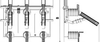
RLVOM single-pole disconnectors consist of a frame with a drive shaft, support insulators, contacts and knives.
The principle of operation and control of the RLVOM disconnector is similar to the RV disconnector (see below).
The disconnector may have one additional insulator with a fixed contact, which is installed on a support, directly in the switchgear, and is used to switch the electrical circuit (change the circuit).
Three-pole disconnectors
Disconnectors RV
Three-pole disconnectors RV consist of three current conductors mounted on one frame with a common shaft, rods and a drive lever. The conductor consists of two fixed contacts and a movable knife connecting them. In three-pole disconnectors, the blade is held in the on position by rods and a shaft.
By rotating the shaft using a PR-P drive (front connection) or PR-10 type (rear connection), the movable knives are turned on or off.
Disconnectors RVZ
RVZ disconnectors, unlike RV, depending on the version, have one or two shafts with grounding blades. A separate drive is required to control each ground shaft.
RVZ disconnectors provide a mechanical interlock between the shaft of the main knives and the shaft of the grounding knives, which eliminates erroneous operations between the grounding and main knives.
RVF disconnectors
RVF disconnectors differ from RV disconnectors by the presence of bushing insulators (instead of support ones) on one side or on both sides. Depending on the design, the disconnectors have three shapes and are intended for installation where an isolated transition from one room (compartment) to another is required without additional bushings.
Disconnectors RVFZ
RVFZ disconnectors are similar in design, principle of operation and purpose to RVF and RVZ disconnectors. Fixed contacts of all types of disconnectors are equipped with fasteners for connecting current-carrying busbars. Contacts of the KSA series are used as switching contacts for external auxiliary circuits. Number of chains - upon request. In T design disconnectors with a rated current of 1000 A, interphase insulating partitions are installed.
Separators
What is a separator?
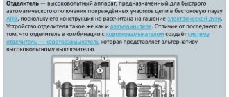
A separator is a high-voltage device designed to automatically disconnect damaged sections of a circuit during a dead-reclosure pause, since its design is not designed to extinguish an electric arc. The separator device is the same as the disconnector. The difference from the latter is that the separator in combination with the short-circuiter creates a separator-short-circuit system which represents an alternative to the high-voltage circuit breaker.
The separator is a disconnector that quickly turns off a de-energized circuit after a command is given to its drive. If in a conventional disconnector the shutdown speed is very low, then in a separator the shutdown process lasts 0.5-1.0 s. The separator disconnects damaged sections of the electrical circuit after the safety switch is turned off. The switch is triggered by an artificial short circuit created by a short circuit.
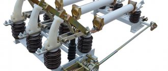
The separators are a two-column disconnector with grounding knives (ODZ); one ODZ-1A, ODZ-1B, two ODZ-2 or without them (OD), controlled by the SHPO drive (separator drive in the cabinet). Up to 110 kV inclusive, three poles of the separator are connected into a common three-pole device and controlled by one SHPO drive.
Separators for 220 kV are made in the form of three separate poles, each of which is controlled by an independent drive.
The separator is switched off automatically under the action of wound springs when a blocking relay or a shutdown electromagnet is activated, releasing the free release mechanism of the drive. The separator is switched on manually.
Operations performed by separators
The separators allow the following operations to be switched off and on:
- voltage transformers, charging current buses and substation equipment of all voltages (except capacitor banks);
- parallel branches under load current, if the disconnectors of these branches are bypassed by other switched-on disconnectors or switches;
- magnetizing currents of power transformers and charging currents of overhead and cable lines;
- neutrals of transformers and arc suppression coils in the absence of a phase-to-ground fault in the network.
Operating principle of separators
Typically, the separator is a chopping-type contact system without arc extinguishing and equipped with a spring-motor drive. In normal mode, the electric motor tensions the spring and places the mechanism on the latch. When a signal is given, the latch is released by a special electromagnetic release and, under the action of a tensioned spring, the separator opens the circuit. This principle (spring shutdown) is necessary for the energy independence of the separator operation (for its reliable operation). It is also necessary to note the mandatory blocking of switching off the separator under current.
Advantages of separators
Cheap - compared to a heavy high-voltage circuit breaker
Disadvantages of separators
Low reliability - since the separators are located mainly in outdoor switchgear, precipitation can lead to failure of the separator.
Design and principle of operation
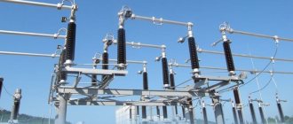
The creation of a high-voltage disconnector was driven by the need for a switching mechanism capable of providing a safe and visually observable break in high-voltage energized circuits. The design of such a device is based on high reliability of contacts, ensuring the circuit is closed and opened in all weather conditions.
The design of the high-voltage disconnector does not provide for the presence of spark-extinguishing elements. Therefore, in order to prevent the formation of a high-power electric arc that can destroy contacts, the devices are connected in series with high-voltage load switches. Before disconnecting the desired line, use a switch to turn off the load.
Short circuits
What is a short circuit?
A short circuiter is an electrical device designed to create an artificial short circuit to ground in power supply networks, in the event of internal damage to the power transformer in the circuit of which, on the high voltage side, it is installed in pairs with a separator. With such a short circuit, the action of linear protections at the supply substations de-energizes the overhead line, the damaged transformer is disconnected from the network by disconnecting the separator, and the line is put into operation by the action of automatic reclosure.
In 110-220 kV networks, short circuiters have one pole, in 35 kV networks - two. The movable knife is activated by the action of the charged closing springs of the short circuit.
Device
Structurally, the short circuit is similar to the ground electrode, but due to the powerful contact system it can be switched on for a short circuit.
Short circuiters are devices of the vertical-cutting type, consisting of a base, an insulating column, a fixed contact with a terminal for connection to a power line and a grounding blade, at the end of which a removable contact plate is attached. At the base of the short-circuit contactor there is a shaft mounted in bearings, two engaging springs with tension adjustment connected to the base and levers of the short-circuit contactor shaft, as well as a hydraulic buffer.
The normal position of the short-circuiter is open. In this case, the knife is moved away from the fixed contact to a discharge distance, and its switching springs are stretched. This position of the knife is fixed by the drive. When a signal is sent to the short circuit breaker drive, the drive releases the short circuit breaker blade, which, under the action of a spring, enters into a fixed contact, creating a short circuit to ground.
Application
Short circuiters together with separators are used in simplified substation circuits instead of more expensive power switches. Such a replacement allows you to save significant money, since the cost of power switches is quite high. The more connections there are in a substation and the higher the high side voltage, the more noticeable the benefits of using simplified circuits become. Basically, simplified circuits have become widespread at voltages of 35 and 110 kV. Short circuiters are installed: in networks with a grounded neutral - for one phase, in networks with an isolated neutral - for two. The short-circuiter is switched on automatically and switched off manually.
Currently, the use of short-circuiters is limited to those substations where they are installed; short-circuiters are no longer produced, since substation circuits where they are used are less reliable and more likely to damage expensive substation equipment (power transformer) than circuits using switches.
Load switches
What are load switches?
The load switch is a three-pole AC switching device for voltages above 1 kV, designed to interrupt operating current, and equipped with a drive for manual or automatic control.
Load switches are not designed to interrupt short-circuit current, but their making capacity corresponds to the electrodynamic resistance during short circuits. In 6-10 kV distribution networks, load switches are often called switches with a breaking capacity of less than 20 kA.
A load switch is a high-voltage switching device that, in terms of the level of permissible switching currents, occupies an intermediate position between a disconnector (switching under load is prohibited, with the exception of transformers and lines being switched on at idle) and a switch (oil, vacuum, air, electromagnetic, SF6) that is capable of disconnecting without damage to both rated load currents and overcurrents in emergency modes. The load switch allows switching the rated current, but is not designed to interrupt currents during a short circuit. Overcurrents in such switches are switched off using special fuses.
Load switch drive
The drive of the load switches can be muscular, directly switching on and off from a pre-tensioned spring. Sometimes an electric activation drive and a remote shutdown solenoid are used.
Types of load switches
- Autogas
- Vacuum
- SF6
- Air
- Electromagnetic
Application
Load switches are installed in 6-10 kV switchgears and substations and allow switching up to several MVA, depending on the design and rated current.
Load switches are used in connections of power transformers on the high voltage side (6-10 kV) instead of power switches, if this is possible under the operating conditions of the electrical installation. Since they are not designed to cut off short-circuit current, the functions of automatically turning off transformers in the event of their damage are assigned to fuses or to switches belonging to previous links in the system, for example, to linear switches located closer to the energy source.
In distribution networks, the most common designs of load switches (VNR, VNA, VNB) with gas-generating type extinguishing devices.
Advantages
- Ease of manufacture and operation;
- Significantly lower cost compared to other switches - several times (especially for gas switches);
- Possibility of switching off and switching on rated load currents;
- Availability of cheap overcurrent protection in the form of fuses. usually filled with quartz sand (type PC, PKT);
- The presence of a visible gap between the contacts, which eliminates the installation of an additional disconnector (a visible gap is necessary for the safety of work on the outgoing line).
Flaws
- Switching only rated powers;
- Short service life (for gas-type load switches).
Principle of operation
Connection or disconnection of the switched electrical circuit is ensured by turning the contact knives. Depending on the design, the moving contacts can be rotated vertically or horizontally. The drive that imparts force to the rotating mechanism is a rod with a handle, with the help of which the operator controls the contact knives. The drive handles are mounted directly on the supports under the disconnector.
Manual control is used mainly on overhead lines up to 6 kV. Knives on lines of 110 kV and above are controlled by electric drives using metal cabinets located at a safe distance.
Fuses
What are fuse switches?
A fuse is a device that, by melting one or more of its parts having a specific design and size, opens the circuit in which it is connected, interrupting the current if it exceeds a specified value for a certain time. The fuse includes all the parts that make up the finished product.
The fuse is the weakest part of the protected electrical circuit, tripping in emergency mode, thereby breaking the circuit and preventing the subsequent destruction of more valuable elements of the electrical circuit by high temperatures caused by excessive current values.
The first fuses began to be used at the end of the 19th century. Since then, their essence has not changed, only the production technology and the quality of their work have changed, both through the selection of materials from which they are made, and by changing the design.
It should be noted that the terms fuse and fuse link have significantly different meanings in modern electrical standards.
Operating principle of a fuse
The so-called fuse is used as a protective element in the fuse. a fuse-link that is located inside a cartridge filled with an arc-extinguishing medium that intensively absorbs heat (quartz sand), for example fuses of the PN-2 or PC types, or without filling, sometimes the autogas principle is used in fuses, when the thermal action of the arc leads to the release of arc-extinguishing gases from the structural elements of the cartridge (fuses of the PR-2 type have this arc extinguishing principle: when an arc occurs, gases are released from the fiber body of the fuse).
The fuse link is made with powerful fuses into plates with cutouts that reduce the cross-sectional area of the insert, while in the nominal mode, excess heat from narrowed places due to thermal conductivity manages to spread to the wide parts and the entire insert has almost the same temperature. When overloaded, the heat does not have time to be completely redistributed throughout the entire volume of the insert and it melts in the hottest place. During a short circuit, the process is so intense that there is practically no redistribution of heat and the insert burns out in several narrowed places.
For faster operation of the fuse (in high-speed fuses), special designs are used (they give the fuse link a special shape), in which the disconnection of the circuit in the fuse at high currents occurs not by melting the insert, but by breaking it by electrodynamic forces (sometimes, to speed up the operation, the fuse link is additionally loaded force of the tensioned spring). To accelerate the melting of the insert, the phenomenon of the metallurgical effect is also used; this solution is usually used in fuses with inserts made of a number of parallel wires (for example, in PC-type fuses).
Some fuse designs use inserts with variable wire cross-sections (PKT type fuses for currents up to 7.5 A): different burnout times for individual sections lead to a reduction in overvoltages when the fuse trips.
An important characteristic of any current protection, incl. and the fuse is time - a current characteristic, usually described in the form of a graph; the current is plotted along the abscissa axis, most often in relative units (the rated current of the fuse-link is taken as a unit), and the response time is plotted along the ordinate. It should be borne in mind that the characteristic of each fuse (even from the same batch) has its own time - current characteristic, which is indicated in the catalog for each type of fuse as a “spread of characteristics zone”, which is guaranteed by the manufacturer.
In this case, it is necessary to keep in mind the difference between the rated current of the fuse and the rated current of the fuse link:
The rated current of a fuse is the current for which the fuse holder is designed.
The rated current of a fuse link is the current for which the fuse link is designed.
In a given size of fuse holder, several inserts with different rated currents can be installed, with the largest one in the rated series usually equal to the rated current of the fuse holder.
Some types of fuses (for example, PCs) have an operation indicator in the form of a spring-loaded pin; when the fuse-link burns out, the indicator pin is ejected by a spring from the fuse body, indicating that the fuse has tripped. Sometimes this pin presses on a special signal contact, sending a signal that the fuse has blown through the telemechanics circuits.
Basic requirements for fuses
The following requirements apply to fuses:
- The time-current characteristic of the fuse should be lower, but as close as possible to the time-current characteristic of the protected object.
- In the event of a short circuit, the fuses must operate selectively.
- The response time of the fuse during a short circuit should be as short as possible, especially when protecting semiconductor devices. Fuses must operate with current limitation.
- The fuse characteristics must be stable. Variations in parameters due to manufacturing deviations should not interfere with the protective properties of the fuse.
- Due to the increased power of installations, fuses must have a high breaking capacity.
- Replacing a blown fuse or fuse link should not take much time.
In industry, fuses of the PR-2 and PN-2 types are most widely used.
Fuse design
All fuse links, regardless of design features, include two main elements:
- fusible element - a conductive element made of metal, an alloy of several metals or specially selected layers of several metals;
- body - a mechanism or system for attaching a fuse element to contacts that ensures the inclusion of the fuse as a whole, as a device, in an electrical circuit.
Fuse-link bodies are usually made of high-strength varieties of special ceramics (porcelain, steatite or corundum-mullite ceramics). For fuse-link housings with low rated currents, special glass is used. The fuse body usually serves as a base part on which a fuse element with fuse contacts, an operation indicator, free contacts, devices for operating the fuse and a rating plate are mounted. At the same time, the housing performs the functions of an electric arc extinguishing chamber.