The technical conditions for connecting to general power supply networks were not invented in vain. Each power line is allocated a certain amount of power. It is limited by the capabilities of the last transformer substation. If you connect consumers with a larger load, the transformer substation will overheat and may fail. If everything goes according to plan (or rather according to the project), there will be no problems. Engineers limit the input power of each facility using a circuit breaker: it will trip if the current exceeds what is allowed by technical conditions. However, in reality the following situations may arise:
- short-term overloads for several subscribers at once, associated either with an emergency or with power surges;
- unauthorized connections to the general line (without taking into account design capacities), which are carried out by careless electricians for a fee;
- illegal replacement of input circuit breakers with a higher current (either independently or with the help of the same electricians);
- banal theft of electricity through temporary unauthorized switching on, bypassing metering devices and input machines.
What happens in such cases?
- The circuit breaker at the output of the transformer substation is constantly triggered (if not, the transformer will simply burn out). In this case, all consumers on this line suffer.
- So-called “drawdowns” occur on the line. The power supply system is self-regulating: to maintain power (without exceeding), and increased current consumption, the voltage is reduced. Many residents of the private sector (especially in garden cooperatives) often observe a value of 160–180 volts instead of 220 on the network.
To combat such phenomena, power limiters are installed. This is an automatic switching device that allows you to disconnect the consumer when deviating from the specified parameters.
What is the purpose of a power limiter?
Many people are familiar with network voltage limiters. This is a protective device that controls the amount of input voltage along a predetermined “corridor”. Such devices can be found in many apartments or households.
The voltage relay really protects electrical appliances from power surges, but that’s where its functions end.
A power consumption limiter (single-phase or three-phase) works on a different principle. More precisely, it has wider functionality:
- Just like a voltage relay, the device monitors the input parameters of electricity. If the value is outside the set parameters, the power to the object is turned off. At the same time, electrical appliances are preserved. After returning to normal, power supply is restored.
- Control functions during operation of electrical installations. The power limiter can maintain parameters to prevent emergency situations.
- Protection against unauthorized connections to your electrical network. You can set strict limits on power consumption on the line, and control your network with an accuracy of 10 W. If an illegal power take-off occurs, the device will turn off the power grid.
How does a power limiter work?
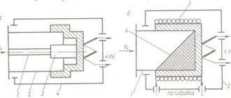
Structurally, the device consists of three independent parts, each of which performs its own function.
The first block records the parameters of the power supply line. Unlike a voltage relay, data is taken for both voltage and current. For this purpose, two transformers are installed in the measuring module. They are galvanically isolated from the power line and do not affect the power network after the device.
The next module is intelligent. He has three tasks:
- Fixing parameters and calculating the instantaneous power value on the line. The program is built on Ohm's laws; engineers have not yet invented anything new. The same module allows you to monitor parameters in real time (the more complex the device, the more indicators can be seen on the display).
- Receiving operator commands: setting operating modes, protection, power limits. Again, depending on complexity (and therefore cost). There is practically no limit to the functionality: the technology is limited only by the common sense of the developer. Three-phase limiters analyze the parameters of each phase. Depending on the specified program, an emergency shutdown can be performed when problems occur in one or several phases.
The actuator performs only one task: upon command from the intelligent module, shutdown. When the control unit “decides” that the parameters are normal: a command to turn on will be received.
The power limiter connection diagram implies two options:
- Installation at the electricity supplier, in which case the device performs a supervisory function. The main task is to control unauthorized power take-off.
- Connection at the consumer after the metering device. The tasks are broader: from monitoring the “theft” of energy to broad protection of your electrical equipment from collisions on the power supply line.
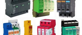
Getting to know your device
The design of a power limiter can consist of various element bases:
- electromechanical induction relays;
- solid-state (semiconductor) elements;
- microprocessor controllers.
Thanks to the presence of programmable chips, the limiter boasts a wide range of settings, which makes it easy to operate. Adjusting the module is quite simple. In some models, power can be controlled via an installed display.
How to connect the device correctly
Three-phase and single-phase power limiters differ in the way they are switched on. In addition, different models of the same group have their own characteristics. We will look at several popular models that can be used both at large corporate facilities and at home.
Advice:
Despite the fact that purchasing such a device is associated with additional costs, its installation is definitely useful. You will not only get rid of problems with variations in power supply parameters (and this means protecting your electrical appliances and the safety of information on personal computers). Unauthorized connection is a direct loss that can exceed the price of the limiter many times over. In addition, power limiters perform the same tasks as circuit breakers and voltage relays. So you will also save money by not buying several switches instead of one.
Each model is supplied with a data sheet and installation diagrams. To use the device correctly, it is advisable to understand the general connection principle.
Single-phase power limiter OM-1
This device is quite compact and can be easily installed in a panel on a DIN rail. The main purpose is to control the excess power of the line. Additional features: circuit protection against short circuits and neutral wire breakage. Of course, you can set a voltage limit.
OM-1 can work independently, that is, it can switch off with its own contact group. The user only selects the installation scheme according to consumer priority: with normally closed or open contacts (see illustration).
If the consumer current exceeds the parameters of the contact group, additional contactors and magnetic latches can be installed. In this case, the limiter acts as a control switch, and the power lines are opened by third-party devices.
Price overview
You can buy a power limiter at any special electrical store; the price depends on the type of device and its brand.
Limiter outputs To a relay (circuit breaker), which must be present in the network Protection indicators The device is insulated according to IP40 (explosion-proof), terminal block - IP20 (resists the penetration of moisture and large dust particles) Conditional climatic version U3.1 Operating temperature From - 30 degrees up to + 50 Storage conditions It is important to store this electronic device in a dry place, out of direct sunlight. The maximum permissible temperature is 70 degrees Celsius and 50 degrees below zero. Installation is carried out mainly on a DIN rail, installation on poles is possible (if the meter is external) Maximum weight 0.5 kg
| City | How much does the limiter om-310 cost, rubles |
| Moscow | 6400 |
| Ufa | 6350 |
| Voronezh | 6300 |
| Ekaterinburg | 6350 |
| Novosibirsk | 6350 |
| Rostov-on-Don | 6400 |
| Chelyabinsk | 6380 |
| Tyumen | 6350 |
Sales are also carried out at branded dealer centers, these are Novatek, ABB, Scan and others. Before purchasing, be sure to check all quality certificates, device passport and warranty conditions. In most cases, warranty service is valid for 1 year from the date of installation.
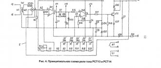
The overcurrent relay is designed to disconnect the load when the current increases above the set value. The power limit relay is designed to measure and continuously monitor the active or apparent power of the load.
Device for monitoring electrical parameters of a single-phase network. Designed to monitor voltage, active/reactive/apparent power, current consumed by the load and subsequent transmission of information via the Modbus RTU protocol.
Device for monitoring electrical parameters of a single-phase network. Designed to monitor voltage, active/reactive/apparent power, current consumed by the load and subsequent transmission of information via the Modbus RTU protocol.
OM-163 is designed to limit power consumption, as well as to (disable) equipment connected to it
OM-163 is designed to limit power consumption, as well as to (disable) equipment connected to it
Power limiting relay with built-in voltage relay OM-110-01 is designed for continuous monitoring of active or total power of a single-phase load.
Power limiting relay with built-in voltage relay OM-110-01 is designed for continuous monitoring of active or total power of a single-phase load.
The device provides operation with a load power from 2.5 kW to 30 kW when using built-in current transformers and up to 450 kW when using external current transformers, including in networks with an isolated neutral.
The device provides operation with a load power from 2.5 kW to 30 kW when using built-in current transformers and up to 450 kW when using external current transformers, including in networks with an isolated neutral.
The maximum current relay RMT-101 is designed to disconnect the load when the current increases above the set value in the range from 0 to 100 amperes.
The maximum current relay RMT-101 is designed to disconnect the load when the current increases above the set value in the range from 0 to 100 amperes.
The maximum current relay RMT-104 is designed for constant monitoring of the effective value of the single-phase load current from 1 to 400 A and its shutdown in case of exceeding the maximum permissible load current specified by the user (MTZ with an independent time delay) with a specified shutdown time and subsequent automatic switching on with a specified time switching on or with restart blocking.
The maximum current relay RMT-104 is designed for constant monitoring of the effective value of the single-phase load current from 1 to 400 A and its shutdown in case of exceeding the maximum permissible load current specified by the user (MTZ with an independent time delay) with a specified shutdown time and subsequent automatic switching on with a specified time switching on or with restart blocking.
Current relays and current limiters, which are presented by the manufacturing company Novatek-Electro, have high performance characteristics that allow the devices to be used for domestic and industrial applications.
Three-phase power limiter OM-630
This device operates independently only when performing protective functions. That is, voltage and current limitations. In this case, the installation diagram looks like this:
Your object is completely protected from collisions on the line; the restart time is set on the control panel. Regardless of the use of three-phase input (consumers can be either 220 or 380 volts), shutdown is carried out if there is a discrepancy between the parameters for any connection method.
If you need power control (the main purpose), the load is connected via a contactor. Shutdown parameters are programmed using a personal computer: a special port is provided for this.
As in the previous case, connection is possible for consumers of different priorities. The circuit provides switching into groups with normally closed and open contacts.
If the power consumption of the entire group is exceeded, those consumers that have a lower priority are switched off first. Essential facilities will remain open.
The shutdown time is programmable: when the timer counts down, the consumers will be powered again.
Despite the pronounced industrial purpose of the OM-630, it can be used in facilities with low power consumption: up to 5 kW. In this case, the connection diagram provides a little trick:
There are vertical through holes in the device body. Cables are passed through them and the load is applied to them. There are as many cables as there are phases in the load.
If the power is below 5 kW, the number of turns is determined by the formula: 5/power consumption. The number is always rounded to a plus. For example, if the power is 2 kW, we get a coefficient of 2.5. This means there will be 3 turns.
This model does not have a digital segment indication of operating modes and emerging problems. Instead, there are indicator LEDs on the front panel. The documentation contains a table from which you can decipher the indicator readings.
Connection features
OM-110
To install the OM-110 power limiter, the following features can be noted:
- Install the OM-110 in its standard place (you can use it under a DIN rail).
- Connect the 220 V network, observing the correspondence between the zero and phase buses.
- Pass the load wire through a special hole - there is a current transformer there, which is a sensor of consumed electricity.
- Connect the contactor according to the diagram. OM-110 works only if there is a contactor that will switch voltage to the load.
- Set the shutdown power using the potentiometer.
- Set the operating time of OM-110 in overload mode.
- Set the time for the limiter to return to its original position after being triggered.
Connection diagram OM-110:
You can see the installation process in more detail in the video below:
After connecting, you need to check the correct operation of the limiter. Apply power and connect a load less than the calculated one. The green LED should be lit. Then you need to connect a load that is higher than the established one. The “overload” LED should light up and after the time set by the “shutdown delay” regulator has expired, it should turn off all consumers. If necessary, the time can be adjusted. After disconnection, the return to its original state occurs automatically. The return time can also be changed using the "restart" control. Installation and configuration of the controller is completed.
OM-310
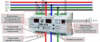
OM-310 is used at a network voltage of 380 V and a power of 3-40 kW. The installation of the power limiter of this series is no different from the previous one. The main difference is that you need to connect three phases of 380 V and a neutral wire to it. There are two indicators on the front panel that allow you to configure and monitor the operation of the device, as well as LED indicators. The setup of this device is somewhat different from the OM-110. The advantage is the ability to connect to a computer and configure it.
Installation consists of connecting all three phases and the neutral wire to the input terminals, as shown in the diagram below:
Visual installation instructions are provided in the video:
The load is connected via current transformers. Set parameters for power consumption, shutdown time during overload and recovery time after shutdown. It is mandatory to use a contactor that switches the load.
OM-630
OM-630 – three-phase power limiter. The connection occurs according to the diagram. Works only with current transformers and load relays.
- Connect the phase wires and the neutral wire.
- Connect a contactor or several as needed
- Pull the load wires through the installed holes in the device body
- Connect the power, after which the LED should light up, and after a specified time the indicator should turn yellow and the load will turn on.
The correct connection is clearly shown in the photo and diagram below:
The maximum power, shutdown time and recovery time are set using switches. All controls are located on the front panel. In addition to the above functions, the OM-630 has a trip counter function. When the limiter is triggered more than a certain number of times within an hour, the load is switched off for 10 minutes. This adjustment is also present on the front panel.
The video below clearly shows how to connect and configure the OM-630:
These devices, regardless of brand and type, protect not only the electricity supplier from overconsumption and theft, but also the consumer from overloading the home electrical network and reducing the likelihood of a fire from overheating of worn-out electrical wiring in the event of a mismatch between the network power and consumption. We hope you found our tips and instructions for connecting 110, 310 and 630 series power limiters useful.
It will be interesting to read:
Source
Three-phase power limiter OM-310
This device has the widest functionality among its analogues.
- Traditional protection against voltage surges. The limiter can replace the digital voltage control relay.
- Overload protection based on the maximum current value, while the parameters can be adjusted linearly or differentially.
- Full RCD functions with finely customizable parameters. Essentially, this is a differential automatic machine in one housing with a power limiter.
- Since the limiter is three-phase, it can be used to control line voltage imbalances and even the phase rotation order. If the shift is incorrect, the protection is also triggered.
The connection diagram is quite complex and varies greatly depending on the use case. We will consider a typical inclusion with different consumer priorities. Of course, external magnetic contactors are used for the load power lines.
Like any other professional device, OM-310 is programmed using a computer using the “COM port” interface format. At the same time, such power limiters can be combined into a network of their own format. In this case, one operator controls the entire system of objects.
For ease of understanding, let’s look at an illustration with a breakdown of the main controls and terminal groups of the OM-310 power limiter:
Despite the apparent complexity of the design, even a novice electrician can easily understand the circuit.