Mathematically cos φ
Mathematically, cos φ is defined as the ratio of active power to total power or equal to the ratio of the cosine of these quantities (hence the name of the parameter).
The power factor value can change in the range 0 - 1 (or in the range 0 - 100%). The closer its value is to 1, the better, since with a value of cos φ = 1, the consumer does not consume reactive power (equals 0), therefore, the total power consumed in general is less.
Low cos φ indicates that increased reactive power is released at the internal resistance of the consumer.
When the currents/voltages are ideal sine waveforms, then the power factor is 1.
Vasiliev Dmitry Petrovich
Professor of Electrical Engineering, St. Petersburg State Polytechnic University
In the energy sector, the following designations are used for power factor: cos φ or λ. If λ is used to determine the power factor, its value is expressed in %.
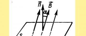
Geometrically, the power factor can be depicted as the cosine of the angle on a vector diagram between current and voltage between current and voltage. In this connection, with a sinusoidal shape of currents and voltages, the value of cos φ coincides with the cosine of the angle from which these phases lag.
A short video about a brief explanation of what power factor is:
How to increase the power factor in sinusoidal current circuits
Influence of reactive current
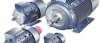
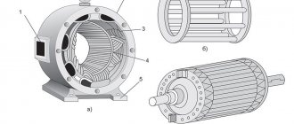
Most modern consumers of electrical energy have an inductive load, the currents of which are out of phase with the source voltage. So for asynchronous motors, transformers, welding machines and others, reactive current is necessary to create a rotating magnetic field in electrical machines and an alternating magnetic flux of transformers. The active power of such consumers at given current and voltage values depends on:
A decrease in power factor
results in an increase in current.
It is especially strongly reduced when motors and transformers are running idle or when there is a large underload. If there is reactive current in the network, the power of the generator, transformer substations and networks is not fully used.
Attention!
With a decrease, energy losses for heating the wires and coils of electrical devices increase significantly.
For example, if the active power remains constant and is provided by a current of 100 A at =1, then when it is reduced to 0.8 and the same power, the current in the network increases by 1.25 times.
Losses for heating the network wires and generator (transformer) windings Pnagr = I2 network x R network are proportional to the square of the current, that is, they increase by 1.252 = 1.56 times.
At =0.5, the current strength in the network with the same active power is 100/0.5 = 200 A, and losses in the network increase 4 times. Voltage losses in the network increase, which disrupts the normal operation of other consumers.
In all cases, the consumer's meter counts the same amount of active energy consumed per unit of time, but in the latter case, the generator supplies the network with a current that is 2 times greater than in the first. The load of the generator (thermal regime) is determined not by the active power of the consumers, but by the total power in kilovolt-amperes, that is, the product of the voltage and the current flowing through the windings.
If we denote the resistance of the line wires Rl, then the power loss in it can be determined as follows:
Thus, the higher the consumer's power factor, the lower the power loss in the line and the cheaper the transmission of electricity.
Power factor
Power factor is a value that shows how the rated power of a source is used.
So, to power the receiver 1000 kW at =0.5, the generator power must be S=P/ =1000/0.5=2000 kVA, and at =1 S=1000 kVA.
Therefore, increasing the power factor increases the power utilization of generators.
To increase the power factor of electrical installations, reactive power compensation is used.
Increasing the power factor (decreasing the angle - phase shift of current and voltage) can be achieved in the following ways:
— replacing lightly loaded engines with engines of lower power;
— voltage reduction;
— turning off engines and transformers running at idle speed;
— inclusion of special compensating devices in the network, which are generators of leading (capacitive) current.
At powerful regional substations, synchronous compensators - synchronous overexcited electric motors - are specially installed for this purpose.
Power factor improvement
The power factor value is calculated when designing networks. Since its low value is a consequence of an increase in the amount of total electricity losses. To increase it, networks use various correction methods, increasing its value to 1.
Increasing cos φ has 3 main objectives:
- reduction of electricity losses;
- rational use of non-ferrous metals to create electrically conductive equipment;
- optimal use of the installed power of transformers, generators and other alternating current machines.
Technically, correction is implemented in the form of introducing various additional circuits to the device input. This technique is required for uniform use of phase power, eliminating overloads of the neutral wire of a 3-phase network, and is mandatory for switching power supplies with an installed power of 100 W or more.
Abrahamyan Evgeniy Pavlovich
Associate Professor, Department of Electrical Engineering, St. Petersburg State Polytechnic University
In addition, compensation makes it possible to ensure that there are no surges in the consumed current at the peak of the sinusoid, and that the load on the supply line is uniform.
Determination of the capacitance of the capacitor for total
compensation of reactive inductive power of the load
.
Goal of the work
: examine an active-inductive load to determine its power factor, inductive reactive current and active power. Based on the measurement data, calculate the capacitance of the compensating capacitor required to fully compensate for the reactive inductive current in the line supplying energy to the load. Compare the current and power before and after connecting the capacitor, determine the reduction in voltage and power loss in the line.
EXPERIMENTAL PROCEDURE.
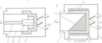
Description of the experimental setup.
The work is performed on a laboratory bench called “Single-phase current”. The stand contains an active-inductive load, a capacitor bank, measuring instruments, and a power source. From all elements on the front panel of the stand there are terminals in the form of terminals necessary for assembling the circuit.
To set the required capacitor capacity, several toggle switches or two brush switches are installed on the stand, allowing you to turn on tens or units of microfarads of capacitance. The total capacity of the capacitor bank is 110 μF. The power supply voltage at terminals A – B, B – C, C – A is 36 volts, at terminals A – N, B – N, C – N 21 volts.
Instruments and measurement techniques.
Ammeters and voltmeters, permanently installed on the stand, have an electromagnetic system of the measuring mechanism. Instruments measure the effective values of variables. Instrument accuracy class is 1.5. Portable laboratory wattmeter of accuracy class 0.5 ferrodynamic system - multi-range. It has three switches: current switch, voltage switch, type of operation switch (current measurement or voltage measurement only, or power measurement). The measurement limit of a wattmeter is determined by the position of its switches:
Pн = In · Un, (5)
where Iн is the current at which the current switch is installed;
Un – voltage to which the voltage switch is set.
The wattmeter division price is determined by the formula:
C = Pn /n, W/div, (6)
where n is the number of divisions of the instrument scale.
The power measured by a wattmeter is:
P = C n׳, (7)
where n׳ is the number of scale divisions shown by the arrow of the device.
In this laboratory work, the measurements use the direct reading method with direct single measurements.
The accuracy of direct measurements is assessed by determining the absolute maximum error using the formula:
ΔА = G XN/100, (8)
where XN is the upper limit of measurement of the device;
G – instrument accuracy class.
The measurement result is written in the form:
A ± ΔA, (9)
where A is the indication of the instrument arrow.
Basic methods of cos φ correction
1. Correction of the reactive component of power is carried out by turning on a reactive element that has the opposite effect. For example, to compensate for the operation of an asynchronous machine with a high inductive reactive component of power, a capacitor is connected in parallel.
2. Correction of nonlinearity of power consumption . When the load's current consumption is disproportionate to the fundamental harmonic of the voltage, a passive (active) power factor corrector is introduced into the circuit to increase the power factor. The simplest example of a passive cos φ corrector is a high-inductance inductor connected in series with the load. The inductor smoothes out pulsed load consumption and creates the lowest, fundamental current harmonic.
3. Correction in a natural way , which does not involve the installation of additional devices, involves streamlining the technological process, rational distribution of loads, leading to an improvement in the electricity consumption of equipment and an increase in the power factor.
Detailed video explaining what cosφ is:
PROCESSING OF EXPERIMENTAL RESULTS
1. Based on observational data, carry out calculations using the formulas:
total circuit power S = I·U, VA;
power factor cosφ = P/S;
capacitance and reactive power of the capacitor according to formulas (3) and (4);
capacitor reactance
Хс= 1/(ω·С) = 106 /(2·π·f·C), Ohm,
where C is in microfarads.
2. The vector diagram of the circuit, Fig. 1b, is constructed in the following order. We select the voltage scale mv = …V/cm and current mi = …A/cm. We plot the network voltage vector U horizontally. Then, at an angle φн in the direction of the lag from the voltage vector, we set aside the current vector Iн. The inductive coil current contains an active current Ia and a reactive inductive current Ip. When connecting a capacitor, the current Ic is delayed by the leading voltage by 90º. The resulting line current is found as the vector sum of the load and capacitor currents using formula (2).
With full compensation of the reactive inductive current, when Iр = Iс, the current in the line Iл coincides with the network voltage.
2. Assess the measurement error using one value of the minimum quantities: voltage, active power, current, apparent power and power factor.
Benefits of Power Factor Correction
The main benefit of power factor correction is the elimination of charges related to reactive power consumption. If the electricity supplier imposes a power factor penalty or charges apparent power (kVA), reducing reactive power provides direct savings. The amount of savings will depend on the size, configuration and operating mode of the system. As a rule, the cost of correction is recouped within a year, and then the savings will reduce operating costs. In addition, power factor correction will improve the performance of the power supply system, as well as increase the service life of the switchgear, starter and motor. So, the key points here are protection, efficiency and savings.
Power types
The actual amount of power used or dissipated in a circuit is called active power. It is measured in watts and is denoted by the capital letter P. Active power is a function of the circuit's dissipation elements, such as resistors (R). Reactive loads (inductors and capacitors) do not dissipate power, but the fact that voltage drops across them and current flows through them gives the impression that they do dissipate power. This “dissipated power” is called reactive power, and its unit is reactive volt-ampere (var). Reactive power is symbolized by the capital letter Q and is a function of the circuit reactance (X). The combination of reactive and active power is called apparent power. It is the product of the voltage and current of the circuit without taking into account the phase angle. Apparent power is measured in volt-amperes (VA) and is symbolized by the capital letter S. Apparent power is a function of circuit impedance (Z). There are several expressions relating three types of power with values of active, reactive and impedance (all use scalar quantities): P – active power, unit of measurement is watt : P = I2R, P = V2/RQ – reactive power, unit of measurement is volt-ampere reactive (var): Q = I2X Q = V2/XS – apparent power, unit of measurement is volt-ampere (VA): S = I2Z, S = V2/Z, S = VI