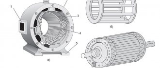
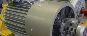
There are several classes of electrical converters, among which the so-called inductive analogues have found practical application. In them, energy conversion occurs due to the conversion of induction windings, which are an integral part of the unit itself. The windings are located on two elements - the stator and the rotor. So, what is the difference between a stator and a rotor (what are they and what are their functions?).
The simplest definition of the two parts of the converter is their functionality. Everything is simple here: the stator (of an electric motor or generator) is a stationary part, the rotor is a movable part. In most cases, the latter is located inside the former, and there is a small gap between them. There are so-called units with an external rotor, which is a rotating ring with a stationary stator inside.
What is an asynchronous motor and its principle of operation
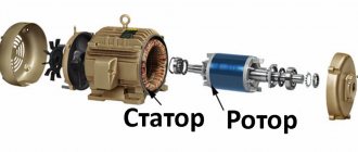
Any electric motor is a device for converting electrical energy into mechanical energy. An electric motor consists of a stationary part (stator) and a moving part (rotor). The structure of the stator is such that it looks like a hollow cylinder, inside of which there is a winding. A moving part, the rotor, is inserted into this cylindrical hole. It also has the appearance of a cylinder, but is smaller in size. There is an air gap between the stator and the rotor, allowing the rotor to rotate freely. The rotor rotates due to currents induced by the magnetic field of the stator. Based on the method of rotation, motors are divided into synchronous and asynchronous.
This is what a disassembled asynchronous motor with a squirrel-cage rotor looks like
An asynchronous electric motor differs in that the rotation speed of the rotor and the magnetic field created by the stator are unequal. That is, the rotor rotates asynchronously with the field, which gives this type of machine its name. Typically, in operating mode its rotation speed is lower. The second name for this type of motor is induction. This name is due to the fact that the movement occurs due to induction currents induced on it.
Asynchronous motor disassembled: main components and parts
The operating principle of an asynchronous motor can be briefly described as follows. When the motor is turned on, current is supplied to the stator windings, which creates an alternating magnetic field. The rotor enters the area of action of the power lines and begins to rotate following the alternating field of the stator.
Definition
From the point of view of electrical engineering, a classic rotor is a rotating cylindrical body with the following structure:
- Shaft made of durable tool steel with at least two bearings, one each at the front and rear;
- Cores made of thick metal plates;
- Coils wound on cores assembled from plates;
- A collector or a pair of special conductive rings.
For forced air cooling of a part rotating very often at high speed, an impeller located at one of its ends is used. In generators, rotation is transmitted to the rotor from a turbine connected to it through a common shaft, or from a running engine using a pulley on which a flexible and durable belt is worn (V-belt drive).
So, the main function of the rotor is rotation relative to the stationary part. In electrical engineering, such a stationary part is the stator. Together, the rotor and stator are the most important components of electric motors and alternators.
Stator
The stator of an asynchronous motor consists of three parts: housing, core and winding. The stator housing serves as a support for the electric motor. It is made of steel or cast iron, by welding or casting. High demands are placed on the strength of the housing, since during operation vibrations occur, which can result in the rotor moving, which will lead to jamming of the motor and its failure.
Asynchronous motor stator
There is one more requirement - the geometry of the body must be ideal. The gap between the stator winding and the rotor is made of several millimeters, so the slightest deviations can be critical.
Stator core
The stator core of an asynchronous electric motor is made of stacked metal plates. Since the core is a magnetic circuit, the metal used is magnetic electrical steel. To reduce losses due to eddy flows, the core is made of plates coated with a layer of dielectric (varnish).
The stator core is made up of thin insulated metal plates
The thickness of one plate is 0.35-0.5 mm. They are assembled into a single package so that the grooves of all plates coincide. The winding turns are then placed into these slots.
Stator winding and motor speed
The stator of an asynchronous electric motor most often has a three-phase field winding. It is called so because it causes the rotor to move. The stator winding consists of coils wound from copper wire that fit into the grooves of the core. Each winding can consist of several turns of wire or one turn. A special wire is used, with a varnish coating, which insulates the turns from each other and from the walls of the core.
As already mentioned, most often the stator winding of an asynchronous motor has three phases. In this case, the axes of the coils are located with a shift of 120°. With this structure, the magnetic field has two poles and makes one full revolution per cycle of three-phase power. With a power supply frequency of 50 Hz, the rotation speed of the field (and rotor) is 50 rpm or 3000 rpm.
Laying the stator winding coils of an asynchronous motor
To reduce the rotor speed in an asynchronous motor, the winding is made with a large number of poles. So with a four-pole starter, the rotation speed will be half as much - 1500 rpm. A winding with six stator poles gives a three times lower speed - 1000 rpm. With eight poles - four times less, i.e. 750 rpm. Even “slower” electric motors are made very rarely.
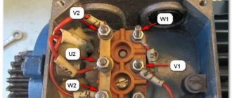
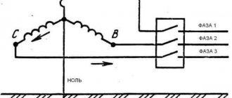
The ends of the stator windings are led out to the terminal box of the housing. Here they can be connected according to the “star” or “delta” principle, depending on the type of power supplied (220 V or 380 V).
Rotor - centrifugal pump
The rotor of a centrifugal pump is one of the most complex and critical assembly units and largely determines the reliability of the pump as a whole.
The rotors of centrifugal pumps, ship propellers, and water turbine rotors have, under the influence of water rotating together with them, a greater moment of inertia than corresponds to their mass.
The rotor of a centrifugal pump is one of the most complex and critical assembly units and largely determines the reliability of the pump as a whole.
The rotor of a centrifugal pump (Fig. 7.18 c) consists of a shaft 3, a set of impellers 4, parts for unloading axial force 5, protective 2 and water-repellent (oil-bump) rings 6, a coupling half / - and fasteners.
For rotors of centrifugal pumps, three classes of balancing accuracy are established: zero, first and second.
Before starting, the centrifugal pump rotor must be turned by hand several times to ensure that the pump shaft rotates freely; Close the pressure valve tightly and fill the pump with the pumped liquid. Methods for filling pumps with the pumped liquid can be different.
During operation, the rotor of a centrifugal pump experiences a significant axial force directed towards the suction part. The value D2 - D3 is always greater than D2 - Dlt, therefore the force P2 is always greater than P1 and the resulting forces P2 and P1 are directed towards the suction part of the wheel.
The axial unloading system of the centrifugal pump rotor is an automatic control system and must satisfy the conditions of dynamic stability.
Heels, rotor nuts of centrifugal pumps; adjusting fittings for deep-well pumping units and fountain fittings; teeth, support rollers and slopes of rotary trench excavators and other parts.
Thus, for a centrifugal pump rotor, for example, weighing 30 6 kgf with a wheel diameter of 0 3 m, the value of the residual imbalance located on its outer circumference should not exceed 1 5 - 2 gf.
Why is the rotor of a centrifugal pump balanced?
What are the main parts of a centrifugal pump rotor?
Currently, for dynamic balancing of centrifugal pump rotors, electric and electromagnetic balancing machines are increasingly used, on which the magnitudes and coordinates of the imbalance are determined using appropriate electrical devices.
| A device for increasing the accuracy of dynamic balancing of the impeller and pump rotor. |
The accuracy of dynamic balancing of impellers and rotors of centrifugal pumps can be improved using the device shown in Fig. 2.63. At the inlet and outlet of the impeller 2 there are plugs 1 made of transparent material. In channel 5, connected to the density of the impeller 2, an elastic membrane 4 is installed, separating the cavities of the rotor 3 and impeller 2 from the atmosphere.
Rotor
The rotor of an asynchronous electric motor comes in two types: squirrel-cage and phase. Most often there are machines with a squirrel-cage rotor. Their advantage is their simplicity of design and uncomplicated manufacturing technology. What is also important is that in such motors there is no contact with the dynamic structure. This increases durability and makes maintenance less frequent and easier.
An asynchronous motor can be squirrel-cage or phase-cage
Asynchronous electric motors with a wound rotor have a more complex design. But they allow you to smoothly regulate the speed without additional devices, and have high torque from the start. So you have to choose: a simpler design or the ability to adjust the rotation speed.
Squirrel-cage rotor device
The rotor consists of a shaft and a cylindrical structure of squirrel-cage rods. Externally, this design is very similar to a squirrel wheel, which is why it is often called a short-circuited rotor winding.
Squirrel-cage rotor device
Initially, both the rods and the end rings were made of copper. The rotors of modern asynchronous motors with power up to 100 kW are made of aluminum rods, with aluminum closing disks. The distance between the rods is again filled with aluminum alloy. The result is a squirrel-cage rotor, but with a continuous coating.
Since a significant amount of heat is generated during operation, the squirrel wheel jumpers are made with additional ventilation blades for cooling. This is how self-cooling occurs during operation. The higher the rotation speed, the more efficient it works.
How an asynchronous motor works: design and arrangement of parts
The rotor is installed in the stator, the ends of the shaft are fixed using covers with mounted bearings. This is a brushless (brushless) motor. No additional contacts or electrical connections. The moving part of the motor begins to rotate in the presence of a magnetic field on the stator. It occurs after power is applied. This field rotates, causing objects that are in its field to rotate. A simple and reliable design, which determined the popularity of electric motors of this type.
Read also: Where is uranium ore mined in Russia
How a wound rotor is made
The structure of the phase rotor is not much different from the stator winding. The same type-setting rings with grooves for laying copper coils. There are three rotor windings, they are usually connected by a star.
This is what a wound rotor of an asynchronous motor looks like
The ends of the rotor windings are attached to copper slip rings. These rings are rigidly fixed to the shaft. In addition, they are necessarily insulated from each other and have no electrical contact with the steel shaft (attached to the rod through dielectric spacers). Since the presence of rings is a distinctive feature of this type of engine, they are sometimes called ring engines.
Asynchronous motor with wound rotor
To fix the rotor to the stator housing, two covers with bearings are made. Brushes are attached to one of the covers, which are pressed against the rings on the shaft, due to which they have good contact with them. To regulate the rotation speed, the brushes are connected to a rheostat. By changing its resistance, we change the voltage, and with it the rotation speed.
Which is better short-circuited or phase-circuited?
Despite the fact that motors with a phase rotor start better and allow you to smoothly change the speed during operation using a conventional rheostat, squirrel-cage motors are more often used. This design does not have brushes, which are the first to fail. In addition, a simpler design of the moving part reduces the cost of the engine, the unit lasts longer, and maintenance and servicing are easier.
Which is better: squirrel-cage rotor or phase rotor
However, it is worth taking a closer look at the advantages and disadvantages of both types of asynchronous motors. So, the advantages of a squirrel-cage asynchronous motor:
- Simple design.
- Easy maintenance.
- Higher efficiency.
- No sparking.
- Low starting torque.
- High starting current (4-7 times higher than the rated current).
- There is no way to adjust the speed.
The magnetic field of the three-phase stator pushes the rotor
Due to the high starting current, direct switching is permitted for motors up to 200 kW. More powerful ones require ballasts. Usually a frequency converter is used, which smoothly increases the current, providing a smooth start without overloads.
Advantage of asynchronous phase motor:
- Quick and hassle-free start.
- Allows you to change the speed during operation.
- Direct connection is possible with virtually no power limitation.
There are also disadvantages: the presence of brushes, the possibility of sparking, complex and frequent maintenance.
How is the speed adjusted?
As already written, the rotor speed depends on the number of stator poles. The greater the number of poles, the lower the speed. But this is not the only way to regulate the rotation speed. It also depends on the supply voltage and frequency.
Methods for regulating the frequency of an asynchronous motor
The voltage can be adjusted by installing a potentiometer at the input. The frequency is regulated by installing a frequency converter. A frequency converter is a more profitable solution, since it also reduces starting currents and can be programmable.
Housing - rotor
The rotor housing is steel, cast; beaters 6 made of wear-resistant steel or bleached steel are fixed in the grooves with wedges. Steel disks are attached to the ends of the rotor with screws; several reflective plates 4 with lining are hinged to the upper part of the body. The space between the rotor, baffle plate and side lining plates forms the crushing chamber. Each reflective plate has a unit 5 for adjusting the width of the output slot - the smallest distance between the rotor circumference and the point closest to it on the lower edge of the plate.
| Sluice feeder designed by TsNIIHP. |
The rotor housing is also cast. It has a funnel 3 in the upper part, through which the transported material enters, and in the lower part there is a channel / / for supplying compressed air. The channel is separated from the housing cavity by a partition 10, in which there are inclined holes 9 located at an angle of 45 to the axis of the feeder.
The rotor body is a series-connected concentric-circular cylindrical shell of constant and variable thickness. The cylinders are mated to each other with conical transitions or directly connected to each other, forming a stepwise change in thickness with different transition radii. The structural shapes and sizes of windows and holes for nozzle holders in separator construction are very diverse. Some of the forms used are shown in Fig. 6.3. At the bottom, the drum body ends with a bottom, at the top - with a flange.
| Mixing-settling circuit diagram. |
The rotor housing consists of inner and outer concentric shells 6 and 7, closed at the ends by side walls. Inside the rotor there is a package of concentric cylinders 8, located with a gap relative to the side walls of the housing; the cylinders are fixed in two side disks. The cylinders have round, flat holes, either in the form of short nozzles or a rectangular shape with flanging, on which the efficiency of phase separation significantly depends. The holes in adjacent cylinders are arranged in mutually opposite groups, which makes it possible to lengthen the path and increase the duration of contact of liquids.
| Non-pressure centrifugal extractor. |
The rotor housing consists of an inner and outer / concentric shells, closed at the ends with side walls. Inside the rotor there is a package of 8 perforated concentric cylinders. The efficiency of mass transfer significantly depends on the shape of the perforations.
The rotor housing is steel, cast; beaters 6 made of wear-resistant steel or bleached cast iron are fixed in the grooves with wedges. Steel disks are attached to the ends of the rotor with screws.
| Mixing-settling circuit diagram. |
The rotor housing consists of inner and outer concentric shells 6 and 7, closed at the ends by side walls. Inside the rotor there is a package of concentric cylinders 8, located with a gap relative to the side walls of the housing; the cylinders are fixed in two side disks. The cylinders have round, flat holes, either in the form of short nozzles or a rectangular shape with flanging, on which the efficiency of phase separation significantly depends. The holes in adjacent cylinders are arranged in mutually opposite groups, which makes it possible to lengthen the path and increase the duration of contact of liquids.
In this case, the rotor housing is simplified, since it consists of only a shaft with a large conical base of the cylinder block, a ring gear and a flat distributor, and a lower conical disk with grooves for securing the working body block. This design is also suitable for double-sided conical rotors, the block working element of which will contain one more element - a guide for the second axial slider.
The rotor housing consists of inner and outer concentric shells 6 and 7, closed at the ends by side walls.
The rotor housing is steel, cast; beaters 6 made of wear-resistant steel or bleached cast iron are fixed in the grooves with wedges. Steel disks are attached to the ends of the rotor with screws.
MB rotor housings are made of diamagnetic materials - aluminum alloys AK-4, AK-6, D16, containing additives of copper, magnesium, nickel, iron, silicon. These alloys are well processed, have a low coefficient of linear expansion, and are ductile when hot. Case blanks in small-scale production are produced by forging. In mass production, depending on the size of the rotor, hot stamping is used for this purpose. The blanks are thermally treated by hardening (490 - 520 C), artificial (150 - 165 C) or natural aging. They are then monitored using an ultrasonic diffractometer for the absence of internal defects.
Single phase asynchronous motor
A three-phase asynchronous motor was considered above; there are two of them in a single-phase asynchronous motor. One is working, the second is auxiliary. The auxiliary is needed in order to give initial rotation to the rotor. Therefore it can also be called starting or starting.
A single-phase asynchronous motor has two windings: working and auxiliary (starting or cranking)
When one winding in the stator is turned on, it creates two equal magnetic fields rotating in different directions. If you introduce a rotor into this field that already has some initial rotation, the magnetic field will maintain this rotation. But how to start the rotor at the start? How to give it rotation, because from one winding two equal magnetic fields arise, directed in different directions. So it is impossible to make the rotor rotate with their help. In the simplest version, rotation is set manually - mechanically. The rotation then picks up the field.
To automate the start of a single-phase asynchronous motor, an auxiliary winding was made. It is designed in such a way that it suppresses one of the components of the magnetic field of the main winding and enhances the second. Accordingly, one of the components outweighs, setting the rotation of the rotor. Then the starting winding is turned off, and the main winding maintains rotation.
The widespread use of the asynchronous electric motor (IM) is due to its reliability and simplicity of design. The stator of such a motor is standard; it is a hollow cylinder made of electrostatic steel plates with a three-phase winding. The rotor can be squirrel-cage and phase. The latter option has become more widespread for a number of reasons, although its design is much more complex than that of a squirrel-cage rotor.
Wound rotor design
The phase rotor of the IM is structurally similar to its stator. The rotor base is made of electrostatic steel plates, which are mounted on the shaft. The design has longitudinal grooves into which the turns of the phase winding coils are placed. The number of rotor phases strictly corresponds to the number of stator phases. To connect the rotor winding to the circuit, 3 slip rings are installed on the latter’s shaft, to which the ends of the winding are connected, which are in contact with the conductive brushes. In turn, the brushes have outlets into the housing box, which will allow you to connect external additional resistance.
Depending on the network voltage, the winding phases are connected in a “triangle” or “star”. The axes of the coils of a two-pole electric motor are shifted 120 degrees relative to each other.
Slip rings are made of brass or steel. They are mounted on the shaft with mandatory insulation between each other. The brushes are located on a brush holder, made of metalgraphite, and pressed against the rings by means of springs.
Meaning of the word ROTOR. What is ROTOR
Electrical diagram of KamAZ trucks
Rotor - (from Latin roto - to rotate)
In mathematics:
A rotor is the same as a vortex of a vector field, that is, a vector characterizing the rotational motion at a given point of the vector field.
The rotor of a polyhedron is a convex body capable of freely rotating in a polyhedron, constantly touching all its faces; see body of constant width and figure of constant width.
In medicine:
Rotor syndrome is one of four forms of hyperbilirubinemia syndrome.
In technology:
A rotor is a rotating part of engines and working machines on which organs are located that receive energy from the working fluid (for example, the rotor of a Wankel engine) or transfer it to the working fluid (for example, the rotor of a rotary pump). The rotor of the engines is connected to the drive shaft, the rotor of the working machines is connected to the drive shaft. The rotor is made in the form of drums, disks, wheels.
Rotor is the rotating part of a steam turbine, compressor, hydraulic pump, hydraulic motor, etc.
A drilling rotor is a mechanism that is multifunctional equipment of a drilling rig, which is designed to rotate drill pipes and support a string of drill or casing pipes during make-up and break-out during tripping operations, during exploratory drilling and overhaul of wells. Drive - chain or cardan. Rotary drilling.
Rotor is a device that controls the rotation of the antenna in the direction of receiving or transmitting a signal.
Rotor is any rotating body in balancing theory.
Rotor - fan system.
In electrical engineering:
The rotor is the rotating part of an electrical machine (generator or alternating current motor inside a stationary part - the stator). The rotor of an asynchronous electric machine is usually a cylindrical body assembled from sheet electrical steel with grooves to accommodate the winding. The rotor in DC electric machines is called an armature.
A rotor is an automatically controlled machine (transport device, device) in which workpieces move along with the tools processing them along circular arcs. Rotary oven. Rotary excavator. Rotor line (rotor complex).
In aviation:
The rotor is the main rotor of a helicopter.
In wind energy:
The Darrieus rotor is an integral part of a vertical-axis wind generator, the impeller of which consists of biconvex blades secured by rods on a vertically rotating axis.
The Savonius rotor is an integral part of a vertical-axial wind generator in the form of two semi-cylindrical blades offset relative to each other and a small (10-15% of the blade diameter) overlap, which form parallel to the axis of rotation of the rotor.
In shipbuilding:
A Flettner rotor is a “sail mast” or a rotor that replaces sails (there are several of them installed on a ship), with the help of which the ship is propelled by the wind, thanks to the Magnus effect. Flettner rotary vessel.
Proper names:
Arturo Rotor (1907–1988) - Filipino physician, government official, musician and writer.
ROTOR - Network competition "Russian Online TOP".
NPO "Rotor" is an enterprise - developer and manufacturer of gyroscopic devices for rocket and space technology (USSR, Russia).
Instrument-making is an industrial enterprise in Barnaul.
"Rotor" is a football club from Volgograd.
"Rotor-Volgograd" is a beach football club from Volgograd.
"Rotor" is a training base in Volgograd.
"Rotor" is the official magazine of the Volgograd football club.
ROTOR (Russian Online TOR; pronounced “rotor”) is an online competition organized by the International Union of Internet Activists “EZHE”. It was first held in 1999.
The goals are to identify significant projects and personalities of the Runet and determine trends in its development.
Members of the ROTOR jury, subscribers to the EZHE discussion mail list, are themselves significant and experienced Internet figures, authors of various network projects, which gives the competition credibility.
Why do you need additional resistance?
Additional resistance serves to start the engine with a load on its shaft. As soon as the nominal shaft speed is reached, the resistance is turned off as unnecessary, and the rings are short-circuited. Otherwise, the operation of the electric motor will be unstable and there will be a loss of efficiency.
The role of additional external resistance, as a rule, is performed by a step rheostat. In this case, the engine will also accelerate in steps. Devices are often used that can increase the efficiency of the motor, while relieving the brushes of excessive friction on the rings. After acceleration, the device raises the brushes and closes the rings.
To implement automatic starting of the electric motor, an inductance connected to the rotor winding is used. The fact is that at the moment when the start is carried out, the inductance and current frequency in the rotor are maximum. As the engine accelerates, these indicators drop, and eventually the engine returns to normal operating mode.
The difference between a squirrel-cage rotor and a phase rotor
In a squirrel-cage motor rotor, unlike the phase version, there are no windings. They are replaced by rods closed at the ends with rings made of aluminum or copper. Visually, the design of such a rotor resembles a squirrel wheel, which is where it got its name – “squirrel cage”.
The squirrel-cage rotor is driven into rotation by inducing current by the magnetic field of the stator. To eliminate the pulsation of the magnetic field in the rotor, the rods of the “squirrel cage” are located parallel to each other, but at an angle relative to the axis of rotation. IMs with a squirrel-cage rotor are highly reliable due to the absence of brushes, which fray over time. In addition, their cost is less than that of variants with a wound rotor.
Read also: Screwdriver charger caliber instructions
Rotor - type
| Design of a two-phase induction motor with a thin-walled rotor. |
A squirrel wheel type rotor consists of a magnetically conductive cylinder (made from insulated steel sheets to reduce losses), in the longitudinal grooves of which individual conductors made of copper or aluminum are inserted, closed at the ends by two conductive rings. The operating principle and main characteristics of both types of machines are the same.
A rotor like a turbogenerator rotor consists of three parts: a middle thickened part (barrel) with a length of 2 / 2 2 ( 1 - e / and two outer sections of a smaller diameter (shank) with a length of lel each. The rotor design is symmetrical relative to the middle cross section, therefore, it can be considered only half of the rotor, consisting of load-free and loaded sections.The concentrated load is located at the boundaries of the sections and is taken into account in the conditions of conjugation of these sections.
All rotors are SRM type, profile 5 7, relative volume Vt varies continuously.
The ogee-type rotor has the ability to use parallel connection of magnets.
The rotor winding of the IM type VAKZ is made of a two-layer wave and is laid in a semi-closed groove. The frontal parts of the rotor winding are banded using non-magnetic steel wire.
The installation has a folding rotor.
| Motor torques and speeds.| Motor switching diagrams.| Overall and installation dimensions of DKIR-TV, DKIR-ATV engines. |
The engines have a closed-loop squirrel cage type rotor with a gearbox.
However, for squirrel cage type rotors, the permissible length-to-diameter ratio in terms of mechanical strength is greater than for thin-walled hollow non-magnetic rotors cantilevered to the shaft. This means that with a constant surface required to conduct the main magnetic flux, the diameter of the squirrel cage rotor and its moment of inertia can be reduced by increasing the length.
The short-circuited squirrel cage rotor winding dampens these magnetic fields very effectively in the case of stationary eccentricity and very weakly in the case of rotating eccentricity. The damping efficiency, however, decreases as the number of main field pole pairs increases.
When repairing squirrel wheel type rotors filled with copper, cracks in the rings are welded, and damaged rods are replaced with new ones. The rods are connected to the short-circuit rings by soldering or welding with carbon electrodes.
The mechanical utilization of a claw-type rotor is significantly higher than that of a sprocket-type rotor. The peripheral speed of the claw-type rotor can be increased to 100 m/sec.
Engine with a squirrel cage type rotor.
ID and with a squirrel cage type rotor - DK.
Advantages and disadvantages of an electric motor with a wound rotor
IMs with phase-wound rotors have become widespread due to a number of serious advantages over other machines of this kind. Among them, it is worth noting the high starting torque, as well as the relatively constant rotation speed even under high loads. Such electric motors require less starting current to start, and the design allows the use of automatic starting devices. In addition, these electric machines can withstand prolonged overloads well.
Like any electrical mechanism, wound-rotor electric motors have a number of disadvantages:
- Sensitivity to voltage changes;
- Large overall dimensions
- High price;;
- More complex design due to the rotor circuit with additional resistance;
- Lower power factor and efficiency indicators (relative to IM with a squirrel-cage rotor).
Scope of application of electric motors with wound rotor
Due to their high torque, low starting currents and the ability to operate for a long time at high loads, motors with a wound rotor are used where high electric motor power is needed, but there is no need to smoothly regulate the rotation speed over wide ranges. In addition, these machines are perfectly suited for starting with a load on the shaft.
Due to their high performance, wound rotor motors are most often used on various serious, heavy power equipment, for example, cranes, elevator drives, machine tools, and various lifts. In other words, these engines are used where there is a need to start under load, and not at idle.
Checking a wound rotor motor
To check the stator windings of a three-phase IM for integrity, you need to get to their connection terminals. Then you need to measure the resistance between the phase terminals separately, having first removed the jumpers. If the resistance of any winding is less than that of others, this indicates a short circuit between its turns. In this case, the motor is rewinded.
To check the rotor windings, you need to find the leads from the slip rings. Then you need to make sure that the winding resistances match. If the design of the electric motor provides for a system for disconnecting the rotor windings, the lack of contact may be due to the breakdown of this mechanism, and not to the breakage of the turns.
The following factors may indicate the presence of any malfunction of the blood pressure:
- Reduced rotation speed under load. Characteristic of high resistance in the rotor circuit, weak contact in its winding, low mains voltage
- Deployment of the IM when the rotor circuit is open - short circuit in the rotor winding
- Excessive uniform increase in engine temperature - prolonged overload of the motor or its insufficient cooling
- Heating of the stator winding of a local nature - double short circuit of the stator coils to the housing or between phases, short circuit between turns, incorrect connection of coils in phase with each other
- Heating of the stator steel of a local nature - violation of the insulation between the steel sheets, their melting and burnout, short circuit
- Extraneous noise during AD operation. It can be caused by both bearing failure and insufficient pressing of active steel. Determined by ear by the nature of extraneous noise
- Burnout in the armature winding of the fuses, lack of contact in the supply wiring, failure of the rheostat
For self-diagnosis and correction of electric motor malfunctions, at least minimal knowledge of the design of blood pressure and electrical circuits in general is necessary. However, it is highly not recommended to repair an electric motor with a wound rotor yourself, as this can lead to electric shock.
An asynchronous motor is an alternating current motor whose rotation speed is not equal to the frequency of the voltage in the stator windings. These electric motors are widely used because they are quite durable. Asynchronous single-phase and three-phase motors can operate under significant load for a long time without overheating and maintain their torque. The operation of an asynchronous motor is simple, but its characteristics directly depend on the parameters of the windings and the technology of their installation.
Application area
The induction motor has become widely used as traction, secondary and other types of power components. Considering the features of its design, the absence of sliding contacts, the operation of such a motor is much simpler. Also, the connection diagram does not require complex control devices, if we talk about a simple operating mode with a constant frequency. Plus, the service life before service is much longer, since the internal space and windings are not contaminated with graphite.
An asynchronous electric motor is used in many areas:
- Ventilation systems – due to their durability and ease of operation, motors with squirrel-cage rotors are often used as fans. They withstand long-term operation at maximum speed, providing users or process equipment with intense air flow.
- Conveyors - due to their high torque and ability to maintain it under load, asynchronous motors have become an ideal option for implementing control of moving production lines.
- Servo systems and drive devices - asynchronous motors are especially often used in drive systems on technological equipment. But to organize control of this type of motor, a special connection diagram and a frequency control unit will be required, and the rotor of an asynchronous motor is equipped with neodymium magnets. Such motors are designed to operate at frequencies up to 400 Hz.
- Household sphere. From such a motor you can make various working units for household use or for a small workshop: a fan, controlled dampers, a circular saw, a jointer, and other equipment.
Types of motors
Based on the type of supply network, asynchronous electric motors are divided into:
- Three-phase. The windings of asynchronous motors of this type consist of 3 coils, specially laid in the stator slots. They are designed for use in industry, as they have high efficiency and cosφ close to 1, and to ensure additional savings they work with an energy recovery system during braking, acting as a generator.
- Single-phase asynchronous motor. It is used in everyday life and industry: old washing machines, household fans, refrigeration and other types of equipment. They have lower efficiency and power compared to three-phase ones, which is explained by losses in the stator due to the lack of an additional phase.
Operating principle of the electric motor
- Detailed description of the operating principle of different types of electric motors:
- Operating principle of a single-phase asynchronous electric motor
- Operating principle of a three-phase asynchronous electric motor
- Operating principle of a synchronous electric motor
Asynchronous motor device
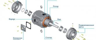
The design of an asynchronous motor is quite simple:
- The stator is the stationary part of the electric motor, which is equipped with field windings.
- The rotor is a rotating element of the motor that rotates under the influence of a magnetic field created by field windings located on the stator. There are 2 types of motors depending on the rotor design: squirrel-cage and phase.
- Flanges are a static part of an electric motor that contains support bearings that hold the rotor and are a kind of fastener for the stator. It is clamped between two flange covers with coupling bolts. Or they are screwed to the stator housing.
- The terminal box is a part of the static motor structure into which the ends of the windings from the stator are led out. Through it, the motor is connected to the control circuit.
- Impeller and protective casing - used to provide forced ventilation, and the casing will protect operating personnel from injury.
- Additional service windings - if necessary, together with the excitation winding on the stator, there can be an additional one designed to control and measure the operating parameters of the motor during its operation.
- Thermal sensors - industrial asynchronous motors, in addition to the windings, there are also temperature sensors that monitor overheating in case of a sharp increase in current consumption.
Read also: Bolt for thread size 19
Also, engines can be equipped with planar gearboxes and manufactured in a single housing. These are mainly industrial types of units used on machines, conveyors and other types of equipment.
Features of the design of each element
The stator of an asynchronous electric motor is a cylinder made of sheets of special electrical steel up to 0.5 mm thick, coated with varnish. This cylinder is the core; on the inside there are grooves where the windings are placed. In three-phase ones, respectively, shifted by 120 degrees, in single-phase ones - by 90. The windings can be laid in several ways, depending on their connection diagram and operational requirements. It is on this that indicators such as torque and power on the shaft depend. And if there are more than 2 pairs of poles, it can be used in servo control systems for drive mechanisms.
The stator is pressed into the housing or located between the flanges. The body and side covers are made of cast iron or aluminum alloy. They have fins to increase the area and increase the efficiency of heat dissipation during operation. This device allows for better engine cooling, ensuring prolonged operation under extreme loads.
The single-pole winding of such an electric motor is wound from 3 coils . Each of them is called a phase. To achieve the required operating parameters of the motor, the winding is placed in opposite slots of the core. The coils are connected to each other in a special way in accordance with the connection diagram and expected characteristics, providing excitation of the magnetic field and the required torque during rotation.
All ends of the sensors are brought out into the terminal box, which allows them to be connected in a star or triangle, which depends on the connection diagram of the control system and the power supply. The 3-phase electric motor is universal; if necessary, it can be connected to single-phase power supply with linear voltage. When the windings are connected in a triangle, the winding voltage is equal to linear Uph, and when connected according to a star circuit – √3Uph.
Rotor
The rotor in an asynchronous electric motor is a shaft on which a core made of sheets of electrical steel is fixed. Whether a three-phase or a single-phase motor, the rotor has almost the same design. As a winding in conventional asynchronous motors with an operating frequency of 50 Hz, pieces of copper or aluminum wire of large thickness or rods connected to each other by end closing rings are used.
In order for the winding to be securely held in the core, there are special grooves into which it is pressed. The end rings can be equipped with ventilation blades designed to improve the cooling intensity of the internal space. The shaft is mounted on bearings pressed into flanges or plates attached to the frame, depending on the device.
There is a gap between the shaft and the stator , the size of which depends on the starting parameters of the motor. If it is necessary to increase power and torque, then it should be as small as possible. Simultaneously with the increase in power, additional losses in the upper layers of the stator and rotor also increase.
Core - rotor
| Spoke rotor frame with laminated segmental rim. |
GAZ 31 029 JZ parahod Logbook Cleaning the XX valve
Rotor frames, the diameters of which exceed 4 5 H - 5 m, are made according to the conditions for their transportation by rail, spoked, detachable.
The rotor frame is forged integrally with the shaft, the poles are massive. The air cooling (ventilation) circuit is closed, two-way symmetrical, radial. Air circulation is carried out due to the pressure created by propeller-type fans and protruding rotor poles. Cooled air enters the machine from both sides at the bottom ends. The air supply to the fans is organized by funnel-shaped diffusers. Propeller fans direct one part of the air flow to the center of the machine from both sides along the axis of the shaft between the poles and into the air gap. This flow cools the poles and is then directed into the radial channels of the stator core, where it removes the heat generated in the stator core and winding. Another part of the air flow passes through the frontal parts of the winding and cools them.
| Rotor of the electric motor SDSZ-4500-1500. |
The rotor frame is made of steel, forged integrally with the shaft. The poles are attached to the rotor frame using T-shaped tails and wedges. The pole cores are made from steel forgings through machining.
| Independent excitation circuit. |
The rotor frame is a drum type, all-welded, consisting of a rim disc hub and stiffeners. The rotor poles, made of sheets of electrical steel 1 mm thick, are tightened with massive jaws and studs. The poles are attached to the rim using bolts. The poles are insulated using fiberglass with epoxy binders.
The rotor frame transmits the generator torque to the shaft, causing deformation of the frame in the horizontal plane. In addition, from the action of weight forces in the frame, deformations arise in the vertical plane, and from the action of centrifugal forces and forces from landing the frame on the shaft and hot wedging of the rim - in radial directions.
The rotor frame of 3 salient-pole synchronous machines can be laminated or welded.
The rotor frame is formed by a steel bushing mounted on the shaft, to the annular flanges of which disks made of thick sheet steel are attached. Welded spokes are attached to the discs with conical pins. The rotor rim is assembled from stamped steel segments, tightened with pins, and hot mounted on the frame.
The skeletons of the rotors, if they exist, and not the shaft itself is also the skeleton, can be integral with the magnetic cores of the rotors (more precisely, with the yokes of the magnetic cores, since the teeth in non-salient-pole structures and the pole cores in salient-pole structures do not bear mechanical load) or act as a supporting structure for magnetic cores. In the first case, they are made of solid disks, mounted directly on the shaft or on the intermediate sleeve.
| Disc frame-rim with step processing of tie rods. |
Rotor frames, the diameters of which exceed 4 5 h - 5 m, are made according to the conditions for their transportation by rail, spoked, detachable.
The compensator rotor frame is made of a hollow forging with attached shafts connected to the frame by shrink fit and flange mounting. The shaft flanges have windows for the entry of cooling gas into the frame. The frame has radial holes through which gas flows to the pole coils.
| Scheme of the NVO rotor of a synchronous compensator - 345 MB-A. |
Principle of operation
The operating principle of an asynchronous motor is quite simple. It is based on two physical phenomena:
- When voltage is applied to the stator windings, a rotating magnetic field appears in the motor.
- The field affects the current induced in the rotor. And this creates a torque that turns the motor shaft relative to the poles.
For each rotation of the shaft, the poles change polarity with the network frequency. Therefore, the voltage of the stator winding has a standard frequency, and the rotation speed depends on:
- shaft loads;
- number of pole pairs;
- features of stator winding.
1. Description of the purpose and design of the proposed part
The shaft is the main and most loaded part of the rotor. The turbine rotor shaft is acted upon by a torque corresponding to the power transmitted by the turbine; bending moment from its own weight and the weight of parts mounted on it; forces of unbalanced steam pressure along the axis. The difficult operating conditions of the shafts and their great responsibility from the point of view of ensuring the reliable operation of the entire turbine require a particularly careful approach to the selection of materials, methods of manufacturing workpieces and subsequent machining, as well as methods and means of quality control of the processed shafts at all stages of the technological process.
Motor marking
To simplify the connection process and selection of an asynchronous 3-phase electric motor circuit, each of them has appropriate markings. It specifies the following characteristics :
- torque;
- power;
- maximum rotation speed;
- cosφ.
Also in the encrypted marking there is an indication of the type of motor and the number of poles. They must be taken into account when choosing a motor for certain needs. And to facilitate the connection process, all ends are brought together into a terminal box, where they are labeled as follows:
If the motor is connected to a 380 V network with a linear winding voltage of 220 V, then its winding circuit must be a triangle . But if the motor is connected to a standard 380V network, then the winding circuit must be a star.
Slip
When considering the operating principle of an asynchronous electric motor, the concept of slip is used, and the parameter is designated by the letter “s”. It arises due to the difference in the speed of rotation of the stator magnetic field and the actual rotor speed. Moreover, the first indicator is an order of magnitude greater. Therefore, the higher the difference, the stronger the slip.
Sliding helps explain the operating principle. Due to the lag of the rotor rotation speed from the stator magnetic field, the EMF is induced in the squirrel-cage rotor. But if the field rotated at the speed of the EMF frequency in the rotor, then the actual rotation would not occur.
Slip, being a relative value, is measured in %. And it becomes larger as the load on the motor shaft increases.
Operating principle of electric motors
Induction motors consist of a rotor and a stator.
The currents in the stator windings are created by the phase voltage, which drives the induction motor. These currents create a rotating magnetic field, also called a stator field. The rotating magnetic field of the stator is determined by the currents in the windings and the number of phase windings.
A rotating magnetic field forms a magnetic flux. The rotating magnetic field is proportional to the electric voltage, and the magnetic flux is proportional to the electric current.
The rotating magnetic field of the stator moves faster than the rotor, which promotes the induction of currents in the windings of the rotor conductors, resulting in the formation of a rotor magnetic field. The magnetic fields of the stator and rotor form their own fluxes, these fluxes will attract each other and create a torque that causes the rotor to rotate. The operating principles of an induction motor are shown in the illustrations on the right.
Thus, the rotor and stator are the most important components of an AC induction motor. They are designed using CAD (Computer Aided Design). Next we will talk in more detail about the design of the rotor and stator.
Wound rotor motor
When it comes to motors with a wound rotor , it has a slightly different device. There are also 3 windings, which are connected in a star, and their beginnings are brought out to the supply rings. Comparing two types of motors with squirrel cage and wound rotors, the second develops torque immediately under high load. Such motors are used in systems where it is necessary to create a powerful drive unit with high traction. Also, such motors are more convenient for controlled control via a frequency regulator.
Disadvantages of asynchronous electric motors
In the standard version without magnets on the rotor, asynchronous electric motors are low-power . They are unable to immediately provide high torque. And also to start them, a large amount of electrical power is required, which may exceed the maximum permissible parameters of the power system. Therefore, they must be started without load. In addition, asynchronous electric motors are powerful sources of electromagnetic interference, accompanied by malfunctions of various other devices located nearby. To reduce their influence, it is necessary to provide high-quality grounding and mandatory shielding.
Types of electric motors
Commutator motors
A commutator machine is a rotating electrical machine in which at least one of the windings involved in the main energy conversion process is connected to a collector [1]. In a commutator motor, the brush-commutator assembly serves as a rotor position sensor and a current switch in the windings.
Universal electric motor
DC brushed motor
Brushless motors
Brushless motors may have slip rings with brushes, so there is no need to confuse brushless and brushless motors.
A brushless machine is a rotating electrical machine in which all electrical connections of the windings involved in the main energy conversion process are carried out without sliding electrical contacts [1].