In the operation of electrical circuits, situations constantly arise when it is necessary to turn on or off any installations and equipment from a distance. To solve these problems, electromagnetic contactors operating with different types of currents are widely used. In the normal operating mode of switching devices, such operations are expected to be performed frequently - approximately 1500 per hour. The design and operating principle of contactors allows them to be actively used to control high-power motors installed on electric locomotives, trams, trolleybuses, elevators and other machinery and equipment.
Components and components of a switching device
There are devices with other types of drives - hydraulic and pneumatic. However, electromagnetic contactors are the main ones because they are more versatile, efficient and wear-resistant.
The operation of electromagnetic type devices is carried out due to the interaction of all units, parts and components that make up the whole device.
Each AC and DC contactor consists of:
- Main (main) contacts. They close and open a high voltage circuit and are capable of operating for a long time under the influence of a current with a set rating. Contact groups can withstand on-off cycles in large quantities and with high frequency. When the contacts return to their normal position, current stops flowing through the retractor coil, and the mechanical latches go into a free state. The design of the main contact group can be lever-type, with a moving system of turns, or bridge-type - with a straight stroke.
- The contactor device includes a chamber for extinguishing the electric arc. Used in DC devices. The design of this element has slots located longitudinally, and direct damping is carried out by the action of transverse magnetic fields. The excitation of such fields is carried out using an arc suppression coil, connected to a series circuit along with contacts.
- Arc extinguishing system. It is used by an AC contactor. With its participation, the electric arc that occurs at the moment when the main contacts open is extinguished. The configuration of this design and extinction methods are selected according to the operating mode and current parameters in a particular circuit. A special lattice structure is installed inside the chamber, when it hits it, a large arc is divided into several small fragments and goes out completely when the current passes the zero mark.
- Parts used in an electromagnetic circuit. This includes the magnetic core, armature and coil, and mounting materials. This circuit allows you to control the device from a distance, turn the circuit on and off. It can be configured to perform certain operations - turn on the anchor and keep it on, or just turn on the anchor. There is a special latch to maintain the closed position. De-energizing the coil and completely turning off the contactor is carried out by the own weight of the entire system, but, as a rule, structures consisting of tripping springs are used for this purpose.
- Additional contacts (auxiliary). Designed for switching in circuits that control the device, and in areas with blocking and signaling functions. Current can pass through these contacts for quite a long time, but not higher than 20 A, and switching off occurs at a current strength of no higher than 5 A. The contacts can be of making or breaking action, many of them have a bridge design.
Markings and types
There are several most common switches. The designation on the surface of the device helps to distinguish them. The brand is also indicated by the certificate and passport of the device. We suggest considering the most common ones:
- KT and KTP are crane contactors operating in direct and alternating current networks. They have extremely high wear resistance - up to several million cycle repetitions. The current frequency should not exceed 50 Hertz, voltage up to 380 Volts;
- KMI are small starters that are used to control the operation of asynchronous motors such as AIR, etc. They operate in a network where the current does not exceed 9 - 95A. The main feature is the ability to install switches in unfavorable areas with high levels of humidity and dust. Their analogue is a device of the KTE 400A EKF class, but in it the maximum permissible current reaches 400 A;
Photo - starter KM-2211 - The purpose of electromagnetic switches of the KTI type from IEK and ABB is similar to KMI, except that they control the operation of three-phase asynchronous motors. In other words, they have a wider range of action. They quickly switch the load (it takes approximately 2 seconds to change modes). Operates up to 660 volts;
- CNEs are used in current networks; they can be marine or tropical. They can be installed on ships, therefore they are widely used at various marine enterprises and motor ships;
- PM and PML belong to household starters, with a current strength of 2 amperes. Quite common in alarm systems and illumination. Their analogues are electro-pneumatic switching devices;
- Thyristor devices of the TKPM-121, KTP-121, KPD-121 series are designed for switching crane mechanisms. They operate under voltages up to 550 volts and frequencies up to 50 hertz. Production is carried out at the IEK plant;
Photo - TKD - Among the imported devices, we can highlight Siemens electromagnetic contactors, whose operating parameters allow them to be used for connecting and monitoring foreign machine tools;
- Starters of the KPV and KTPV types have a magnetic method of eliminating the arc, which is a huge advantage compared to other types. They are actively used for traction stock, electric vehicles and other complex mechanisms.
Operating principle of contactors
The main part of the contactor that immediately catches your eye is the coil of wires. On the inside there is a core connected mechanically to the contacts. These elements close or open an electrical circuit, creating a flow or, conversely, stopping the flow of current. A copper or steel frame shell gives the coil the necessary rigidity and contributes to more efficient cooling of the device parts.
The operating principle of the contactor involves certain actions of the opposite nature. After voltage is applied to the coil, a magnetic field arises, under the influence of which the core begins to move from bottom to top. As a result, the circuit is closed and a current is generated that drives the connected electrical equipment. When the movement of electricity stops, the core, under the influence of the spring system, returns to its original state. As a result, the circuit opens and the electrical equipment turns off.
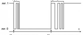
The on/off function of the contactor device consists of the operation of a special push-button mini-device with START (black) and STOP (red) buttons. When you press on each of them, the contacts close and open, respectively. The potential is applied to the coil and the power contacts are closed. They remain on even after the start button is returned to its original state. This function is carried out using auxiliary contact blocks.
The principle of operation of the contactor also lies in the action of the switching circuit, where two circuits are involved. The first of them is the control one, which transmits power to the coil. After closing the contacts, a high-voltage circuit comes into operation, the current in which is much higher than in the control circuit.
Main purpose
When working with electrical networks, an electrician must constantly turn on or off various devices, modules or loads, and also monitor their correct operation. At home, everything is easy; to carry out these processes, switches are used, through which electrical equipment is turned on or off. Such devices are effective and simple, but they have one significant drawback - mechanical wear. Therefore, this type is not suitable for working with large electrical systems, but the contactor will cope with such work with 5 points. In addition, the element has a long service life, which allows switching on and off cycles not a hundred, but tens of thousands of times per hour. But the main feature is completely different - the device makes it possible to control the load while located at a considerable distance from the installation site, which increases operational safety.
Auxiliary contact blocks are used in every area of human life. Thanks to them, street lights are turned on or some power lines (tram, railway lines, etc.) are turned off at a distance. The system is also useful in the construction and manufacturing industries, as it allows you to safely start up powerful power plants or similar equipment.
Contactors are also used in residential buildings, for example, with the help of this device the user can turn on or off an electric heating boiler, control ventilation, a pump used in sewer systems, etc. This is a relatively new device that allows you to control your home in one place, rather than walking from one room to another. Therefore, when building a new cottage, auxiliary contact blocks occupy a separate place.
Such equipment has high electrical safety, as it minimizes the chance of fires due to overvoltage.
The advantages of this equipment include:
- Connection to any electrical network;
- Small dimensions;
- They do not make noise during operation;
- Used for high power or current;
- Easy installation and operation;
- Function in various conditions.
Classification and types of contactors
Since switching devices and circuit breakers are used in many areas, they are produced to perform specific tasks, with the necessary parameters and technical characteristics. This data is necessary when solving the problem of how to choose a contactor.
All types of switching devices can be classified according to their characteristic features and other indicators:
- Currents in all circuits can be constant or variable. It is quite natural that the contactor will also be AC or DC
- The number of main poles is 1-5 units.
- Parameters of the current rating of the power circuit. They are located within the range of 1.5-4800 A.
- Rated voltage characteristics. With direct current - 27-2000 V, with alternating current 110-1600 V. AC frequency indicators are 50, 60, 500, 1000, 2400, 8000 and 10000 Hz.
- Control coil voltage rating. With direct current - 12-440 V, with alternating current - 12-660 V with a frequency of 50 Hz. There are AC devices available at 24-660 V, with a frequency of 60 Hz.
- There are differences in the type of conductor connections in all types of circuits used, installation methods, connection of external wires and other indicators.
Errors in selection
Some people mistakenly look first at the arc chutes, thinking that if they are there, then there is a contactor in front of them.
Allegedly, they are needed to dampen currents, starting from the 5th magnitude. The fifth value is a current equal to I=100A.
At the same time, thinking that the starter is designed only for low currents (up to 100A).
Supporters of this classification even came up with their own gradation:
- relays are devices for low currents
- starters – for medium
- contactors – for high currents
All this is of course not true. One fairly popular brand, namely PML, is most likely to blame for such misconceptions.
For these models, starters are designed for currents from 10 to 100A, and contactors from 10 to 800A. This is where the confusion started.
PMLKMEPAEPMA
Allegedly, if the device is more than 100A, then it belongs to the contactors. Some packages even contain seemingly opposite messages. On one side it says:
- PM – magnetic starter
And then on the other:
- Contactor
What should we believe and what do the rules and documentation say about this? To understand this, first of all, let’s find the definitions of these devices and see what the differences are.
Parameters and technical indicators
The main indicators of electromagnetic contactors include the following:
- Number of main contacts. For direct current devices their number is 1-2, for alternating current - 2-5.
- Indicator of the current rating in the power circuit.
- The value of the maximum switching capacity of the device. Indicates the maximum current that can be switched off by the contactor without loss of performance.
- The rated voltage of the power circuit is no more than 660 V, the control circuit is 12, 24, 48, 110 and 220 V. Based on these data, we select the desired device.
- Resistance to switching wear of starters, up to 2 million cycles. The device must withstand the specified number of switching operations under the influence of current in the power circuit, and be suitable for subsequent use.
- Resistance to mechanical wear, discussed above. Indicates the number of operations without current in the power circuit. For contactors, this figure is 10-20 million cycles; the required device is selected based on it.
- Duration of own switching time. This is the time period from the moment of switching on (the command is given) until the moment when the contacts are completely closed.
- Duration of own shutdown time. It starts from the moment the shutdown command is given until the electric arc is completely extinguished.
- The value of current characteristics on additional contacts, their number and type. According to their functions, they can be of closing or breaking action.
Technical specifications on the contactor itself
Let's start with the contactor from Schneider Electric. The maximum possible power connected to the contactor in horsepower (HP) is indicated on the side edge. This power depends on the supply voltage.
In a number of countries, horsepower is still used, although there are recommendations from the international metrology organization that horsepower should be eliminated from use.
The following are general recommendations for selecting circuit breakers or fuses.
- the inscription CB - Circuit Breaker refers to automatic machines
- Fuse – to fuses
The maximum operating voltage (a.c. max) must be specified.
Cont. current is the continuous rated current at load category AC1.
To put it simply, category AC1 is a load such as an iron or an ordinary heater.
AWG 6-14 Cu - shows the cross-section of wires that can be connected to the contacts.
Measurements are in Western units. In order to find out the analogue of our section in mm2, you will need to use the AWG to mm2 conversion table.
Torque 20lb.in – the torque with which the terminals can be tightened.
More accurate numbers in conventional units of measurement can also be found in the technical data on the manufacturer’s website, or use a special program here that converts lb-in to Nm (newton meters).
Lb-in stands for pounds per square inch.
High-quality contactors always have inscriptions indicating the presence of certificates to which this mechanism corresponds.
Ith-40A – conditional thermal current in open design. Simply put, this is the current that the contactor can pass through itself under normal environmental conditions.
Ui=690V – rated insulation voltage of the product.
IEC/EN 60947-4-1 – starter compliance with this standard. GOST R50030.4.1-2012 is our modified analogue of this standard.
Uimp=6kV – permissible pulse overvoltage.
A separate plate indicates the possible powers connected to the contactor, depending on the supply voltage.
Powers are already registered in kilowatts. Some may wonder why there is such a difference depending on the voltage.
This is explained simply. By and large, the contactor does not care what voltage the load is designed for. The most important thing is the amount of current flowing through its contacts.
For example, you have a voltage of 100V and a current of 10A. The load in this case will be 1 kW.
And if the voltage is 2 times greater, i.e. 200V, then when connecting the same load of 1 kW, a current will flow through the product 2 times less than I = 5A.
Therefore, the lower the voltage, the less power the load can be connected to the contactor. At the same time, always pay attention to what type of load the data is indicated for.
For example, in this case, the powers are indicated for the AC3 load. An example of such a load is an asynchronous motor.
JIS C8201-4-1 is a Japanese industrial standard. Accordingly, the possible powers connected to the contactor are also specified here, depending on the supply voltage according to this standard.
Why is such a large and strange set of voltages prescribed? Because different countries have different standards that determine power voltage levels.
For example, in Japan, a regular outlet has 100 volts. And for powerful loads, 200V is already used.
Structural elements
Each KMI contactor is equipped with a coil or electromagnet, which forms the basis of the device. This component is powered over a wide voltage range - 12-380 volts. Before connecting, you need to accurately set the operating current of the electromagnet, indicated in the passport or on the side of the coil body.
The next important design element is the core. It is a prefabricated structure with metal plates impregnated with varnish. The core consists of fixed and moving parts. The first part is used to accommodate the coil, and the other part - the movable one - is intended to accommodate the movable contacts. The fixed contacts are secured using screws to the plastic body of the device. Movable – attached to the core with a special insulating holder. Short-circuited aluminum rings are pressed into the pole tips of the stationary part, eliminating the effect of detonation.
The contact area of the contact solders in different IEC designs may differ. It depends on the operating current of the power circuits, which can be passed by the contactor. In this regard, each type of device has its own value - first, second, third, etc. Most of them are equipped with four contact pairs: three are intended for the power circuit, and one is additional and performs various functions. It blocks the control circuit, turns on a sound or color alarm, and partially provides automatic relay protection for the control of electrical installations.
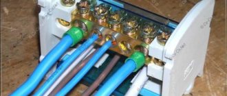
The conductors are connected using special connecting contacts. They have an oval shape, which increases the reliability of fixation. For small wires, hardened disc washers are used, and for large conductors, a clamping clamp is provided. Notches on the contacts further increase the reliability of fixation, increase the contact area and reduce heating of the wires.
When power is applied to the coil, it results in an electromagnetic effect. Under its influence, the metal cylinder begins to move upward, after which the contact closes. The circuit supplying power to the coil is considered the control circuit, and the voltage in it is quite low, within 24 volts. The other circuit that closes the contact is a power circuit, since a current with a voltage of up to 660 volts passes through it. In the absence of power supply, the metal core returns to its original position under the action of a spring, and the circuit is open.
What is the difference between a contactor and a starter?
In fact, a contactor is a device consisting only of an electromagnetic coil and contacts. When voltage is applied to the coil, the contacts close (or open). The contactor does not contain devices for protection, fixation, switching, indication, etc. A starter is a device that contains a contactor as the main component element. In addition, the starter usually contains a thermal relay for protection against overcurrent, START and STOP buttons, an indication, can be enclosed in a housing, and have a circuit breaker for short-circuit protection. In other words, the starter is used to start (turn on) various electricity consumers.
The starter can contain two contactors. This happens in cases where reverse engine control is used, or during a soft start, when a powerful engine is turned on first in a star circuit and then in a delta circuit.
Disassembled starter PML-1220 0*2B. The contactor and thermal relay are visible.
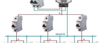
Installation of starters
Electromagnetic contactors are installed in two ways: on a DIN rail or using durable galvanized bolts.
Mounting equipment on a DIN rail
The contactors are mounted on a DIN rail thanks to the presence of a special groove with a retractable stopper on the back of the base. In order to fix the starter, the groove stopper is pulled out to the end, the device is put on a metal or plastic rail 35 mm wide, after which the stopper is returned to its original position. A starter secured in this way can, if necessary, be quickly dismantled and replaced with a new one.
DIN rail
Bolting
The contactor is secured using bolts as follows:
- Several holes are drilled in the panel on which the device is planned to be mounted;
- Using a tap, an internal thread of the required diameter is cut into the drilled holes;
- The bolts are inserted into the holes on the starter body and screwed into the cut threads on the panel.
Compared to a DIN rail, this installation method is more reliable, but it also requires significantly more time and effort.