Refrigeration equipment has become so firmly established in our lives that it is even difficult to imagine how we could manage without it. But classic refrigerant designs are not suitable for mobile use, for example, as a traveling cooler bag.
Cooler bag with Peltier elements, no compressor, no need for freon or other refrigerants
For this purpose, installations are used in which the operating principle is based on the Peltier effect. Let's briefly talk about this phenomenon.
What it is?
This term refers to a thermoelectric phenomenon discovered in 1834 by the French naturalist Jean-Charles Peltier. The essence of the effect is the release or absorption of heat in the area where dissimilar conductors through which electric current passes are in contact.
In accordance with the classical theory, there is the following explanation for the phenomenon: electric current transfers electrons between metals, which can accelerate or slow down their movement, depending on the contact potential difference in conductors made of different materials. Accordingly, with an increase in kinetic energy, it is converted into thermal energy.
On the second conductor, a reverse process is observed, requiring replenishment of energy, in accordance with the fundamental law of physics. This occurs due to thermal vibration, which causes cooling of the metal from which the second conductor is made.
Modern technologies make it possible to produce semiconductor elements-modules with maximum thermoelectric effect. It makes sense to briefly talk about their design.
Heat pump concept
The basic idea of a heat pump is to extract some useful energy from the resulting temperature difference. The output energy may be mechanical, electrical or other. One obvious example, which is often found in everyday practice, is the steam engine. In this case, water is heated to produce steam. In turn, steam, having the property of expansion, creates pressure.
The classic diagram of a heat pump used in practice: 1 – cold cylinder; 2 – radiator; 3 – flywheel; 4 – heat source; 5 – hot cylinder; 6 – steam (gas); 7 – steam (gas) circuit
The resulting pressure is used to perform some work. For example, to push a piston in a mechanical drive cylinder. While doing work, the steam cools, compresses, and condenses. Therefore, for a steam engine to operate, an external temperature is required below the steam temperature. In fact, the operation of all heat pumps depends on temperature differences.
Design and principle of operation
Modern modules are a structure consisting of two insulating plates (usually ceramic), with serially connected thermocouples located between them. A simplified diagram of such an element can be found in the figure below.
Design of a modular Peltier element
Designations:
- A – contacts for connecting to a power source;
- B – hot surface of the element;
- C – cold side;
- D – copper conductors;
- E – semiconductor based on p-junction;
- F – n-type semiconductor.
The design is made in such a way that each side of the module is in contact with either pn or np junctions (depending on polarity). Contacts pn heat up, np contacts cool (see Fig. 3). Accordingly, a temperature difference (DT) occurs on the sides of the element. To an observer, this effect will look like a transfer of thermal energy between the sides of the module. It is noteworthy that changing the power polarity leads to a change in hot and cold surfaces.
Rice. 3. A – hot side of the thermoelement, B – cold side
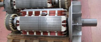
Thermoelectric module
Peltier elements are used in a device consisting of many p and n type semiconductors. Unlike transistors and diodes, transition regions are located at the metal-semiconductor interface. In the Peltier module, a large number of elements are located between ceramic plates, which makes the device more powerful.
Each element contains 4 junctions at the semiconductor-metal contact. When the electrical circuit is closed, electrons move from the battery negative to the positive, passing through all transitions.
At the first transition of the thermoelectric module (TEM) between the copper bus and the p-semiconductor, heat is released in the latter, since the flow of charges enters a region with lower energy.
At another contact in the semiconductor, energy is absorbed as electrons are “sucked” by an electric field that coincides with the direction of their movement. There the cooling process takes place.
At the third contact, the energy of the electrons is absorbed because the n-type semiconductor has more energy than the metal.
At the fourth transition, heat is released as the electrons are again inhibited by the electric field.
Thus, heat is generated on one side, while the other is cooled. On one element this phenomenon will not be noticeable, but the Peltier module, the elements of which are located between two ceramic plates, creates a significant temperature difference.
The module can be used as an electricity generator if the plates are maintained at different temperatures. In this case, each Peltier thermoelectric element is connected in series to the neighboring one through copper jumpers, and their currents are summed.
Specifications
The characteristics of thermoelectric modules are described by the following parameters:
- cooling capacity (Qmax), this characteristic is determined based on the maximum permissible current and the temperature difference between the sides of the module, measured in Watts;
- maximum temperature difference between the sides of the element (DTmax), the parameter is given for ideal conditions, the unit of measurement is degrees;
- permissible current required to ensure maximum temperature difference - Imax;
- the maximum voltage Umax required for the current Imax to reach the peak difference DTmax;
- internal resistance of the module – Resistance, indicated in Ohms;
- efficiency coefficient - COP (abbreviation from English - coefficient of performance), essentially this is the efficiency of the device, showing the ratio of cooling to power consumption. For inexpensive elements this parameter is in the range of 0.3-0.35, for more expensive models it approaches 0.5.
Marking
Let's look at how typical module markings are deciphered using the example of Figure 4.
Figure 4. Peltier module marked TEC1-12706
The marking is divided into three meaningful groups:
- Element designation. The first two letters are always unchanged (TE), indicating that this is a thermoelement. The next one indicates the size, there may be the letters “C” (standard) and “S” (small). The last number indicates how many layers (cascades) there are in the element.
- The number of thermocouples in the module shown in the photo is 127.
- The rated current is in Amperes, for us it is 6 A.
The markings of other models of the TEC1 series are read in the same way, for example: 12703, 12705, 12710, etc.
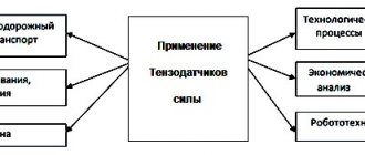
Application
Despite the rather low efficiency, thermoelectric elements are widely used in measuring, computing, and household appliances. Modules are an important operating element of the following devices:
- mobile refrigeration units;
- small generators to generate electricity;
- cooling systems in personal computers;
- coolers for cooling and heating water;
- dehumidifiers, etc.
Let us give detailed examples of the use of thermoelectric modules.
Refrigerator using Peltier elements
Thermoelectric refrigeration units are significantly inferior in performance to compressor and absorption analogues. But they have significant advantages, which makes their use advisable under certain conditions. These advantages include:
- simplicity of design;
- vibration resistance;
- absence of moving elements (except for the fan blowing the radiator);
- low noise level;
- small dimensions;
- ability to work in any position;
- long service life;
- low energy consumption.
These characteristics are ideal for mobile installations.
Thermoelectric auto-refrigerator installed in the car interior
Peltier element as an electricity generator
Thermoelectric modules can work as electricity generators if one of their sides is subjected to forced heating. The greater the temperature difference between the sides, the higher the current generated by the source. Unfortunately, the maximum temperature for the thermal generator is limited; it cannot be higher than the melting point of the solder used in the module. Violation of this condition will lead to failure of the element.
For mass production of thermal generators, special modules with refractory solder are used; they can be heated to a temperature of 300°C. In ordinary elements, for example, TEC1 12715, the limit is 150 degrees.
Since the efficiency of such devices is low, they are used only in cases where it is not possible to use a more efficient source of electrical energy. However, 5-10 W thermal generators are in demand among tourists, geologists and residents of remote areas. Large and powerful stationary installations powered by high-temperature fuel are used to power gas distribution units, meteorological station equipment, etc.
Thermoelectric generator B25-12 (M) 12 volt, 25 watt
To cool the processor
Relatively recently, these modules began to be used in CPU cooling systems of personal computers. Considering the low efficiency of thermoelements, the benefits of such structures are rather doubtful. For example, to cool a heat source with a power of 100-170 W (corresponding to most modern CPU models), you will need to spend 400-680 W, which requires installing a powerful power supply.
The second pitfall is that an unloaded processor will release less thermal energy, and the module can cool it below the dew point. As a result, condensation will begin to form, which is guaranteed to damage the electronics.
Those who decide to create such a system on their own will need to carry out a series of calculations to select the power of the module for a specific processor model.
Based on the above, using these modules as a CPU cooling system is not cost-effective; in addition, they can cause computer equipment to fail.
The situation is completely different with hybrid devices, where thermal modules are used in conjunction with water or air cooling.
Thermoelectric cooler Armada
Hybrid cooling systems have proven their effectiveness, but the high cost limits the circle of their admirers.
Air conditioner based on Peltier elements
Theoretically, such a device will be structurally much simpler than classic climate control systems, but it all comes down to low performance. It’s one thing to cool a small volume of a refrigerator, another thing to cool a room or the interior of a car. Air conditioners using thermoelectric modules will consume more electricity (3-4 times) than equipment running on refrigerant.
As for using it as a car climate control system, the power of a standard generator will not be enough to operate such a device. Replacing it with more efficient equipment will lead to significant fuel consumption, which is not cost-effective.
In thematic forums, discussions on this topic periodically arise and various home-made designs are considered, but a full-fledged working prototype has not yet been created (not counting the air conditioner for a hamster). It is quite possible that the situation will change when modules with more acceptable efficiency become widely available.
For cooling water
The thermoelectric element is often used as a coolant for water coolers. The design includes: a cooling module, a thermostat-controlled controller and a heater. This implementation is much simpler and cheaper than a compressor circuit; in addition, it is more reliable and easier to operate. But there are also certain disadvantages:
- water does not cool below 10-12°C;
- cooling takes longer than its compressor counterpart, therefore, such a cooler is not suitable for an office with a large number of employees;
- the device is sensitive to external temperature, in a warm room the water will not cool to the minimum temperature;
- Installation in dusty rooms is not recommended, as the fan may become clogged and the cooling module may fail.
Tabletop water cooler using Peltier element
Air dryer based on Peltier elements
Unlike an air conditioner, the implementation of a dehumidifier using thermoelectric elements is quite possible. The design is quite simple and inexpensive. The cooling module lowers the temperature of the radiator below the dew point, as a result, moisture contained in the air passing through the device settles on it. The settled water is discharged into a special storage tank.
A simple and inexpensive Chinese dehumidifier using Peltier elements
Despite the low efficiency, in this case the efficiency of the device is quite satisfactory.
Assembly master class
So, we found on the Internet very detailed and at the same time simple instructions for assembling a homemade electricity generator based on a furnace and a Peltier element. To begin, you need to prepare the following materials:
- The Peltier element itself with the parameters: maximum current 10 A, voltage 15 Volts, dimensions 40 * 40 * 3.4 mm. Marking – TEC 1-12710.
- An old power supply from a computer (only the case is needed from it).
- Voltage stabilizer with the following technical characteristics: input voltage 1-5 Volts, output voltage – 5 Volts. This instruction for assembling a thermoelectric generator uses a module with a USB output, which will simplify the process of recharging a modern phone or tablet.
- Radiator. You can take it from the processor immediately with a cooler, as shown in the photo.
- Thermal paste.
Having prepared all the materials, you can proceed to making the device yourself. So, to make it clearer to you how to make a generator yourself, we provide a step-by-step master class with pictures and a detailed explanation:
- Disassemble the old power supply and leave only the housing. It will be used as a place to ignite the fire (the so-called oven).
- Glue the Peltier plate with thermal paste to the flat surface of the radiator. You need to glue the markings to the radiator, this will be the cold side. If you reverse the polarity, you will subsequently need to reverse the polarity of the wires in order for the thermoelectric generator to work correctly.
- Glue the power supply housing to the back of the module, as shown in the photo below.
- Solder a stabilizer with a USB output to the terminals of the plate. By the way, you can make a soldering iron with your own hands to make connections.
- Carefully place the 5-volt converter in the radiator and proceed to testing a homemade thermoelectric generator.
The thermoelectric generator works as follows: you put wood inside the furnace, set it on fire and wait a few minutes until one side of the plate heats up. To recharge the phone, the difference between the temperatures of different sides must be about 100°C. If the cooling part (radiator) gets hot, it needs to be cooled by all possible methods - gently pour water on it, place a mug of ice on it, etc.
And here is a video that clearly shows how a homemade wood-burning electric generator works:
You can also install a computer fan on the cold side, as shown in the second version of a homemade thermoelectric generator with a Peltier element:
In this case, the cooler will use a small fraction of the power of the generator set, but the resulting system will be more efficient. In addition to telephone charging, the Peltier module can be used as a source of electricity for LEDs, which is an equally useful option for using a generator. By the way, the second version of a homemade thermoelectric generator is a little similar in appearance and design. The only upgrade, besides the cooling system, is the ability to adjust the height of the so-called burner. To do this, the author of the element uses the “body” of a CD-ROM (one of the photos clearly shows how you can make the design yourself).
If you make a thermoelectric generator with your own hands using this method, you can have up to 8 Volts of voltage at the output, so to charge your phone, do not forget to connect a converter that will leave only 5 V at the output.
Well, the last version of a homemade power source for the home can be represented by the following diagram: an element - two aluminum “bricks”, a copper pipe (water cooling) and a burner. The result is an effective generator that allows you to create free electricity at home!
So we have provided three simple options for a homemade device that can be assembled from available materials. Now you know how to make a thermoelectric generator with your own hands, what the operating principle of the Peltier element is based on and what it can be used for!
Interesting reading:
- How to legally pay less for electricity
- How to make a solar battery with your own hands
- Economical garage heating with electricity
How to check the Peltier element for functionality?
The simplest and most reliable method is tactile. It is necessary to connect the module to the appropriate voltage source and touch its different sides. For a working element, one of them will be warmer, the other colder.
If you don’t have a suitable source at hand, you will need a multimeter and a lighter. The verification process is quite simple:
- connect the probes to the module terminals;
- bring the lit lighter to one of the sides;
- We observe the readings of the device.
In the working module, when one of the sides is heated, an electric current is generated, which will be displayed on the device display.
How to make a Peltier element with your own hands?
It is almost impossible to make a homemade module at home, especially since there is no point in doing so, given their relatively low cost (about $4-$10). But you can assemble a device that will be useful on a hike, for example, a thermoelectric generator.
Connection diagram for a homemade thermogenerator
To stabilize the voltage, it is necessary to assemble a simple converter on the L6920 IC chip.
Schematic diagram of a voltage converter
The input of such a converter is supplied with a voltage in the range of 0.8-5.5 V, and at the output it will produce a stable 5 V, which is quite enough to recharge most mobile devices. If a conventional Peltier element is used, it is necessary to limit the operating temperature range of the heated side to 150 °C. To avoid the hassle of tracking, it is better to use a pot of boiling water as a heat source. In this case, the element is guaranteed not to heat above 100 °C.
Research part
Actually, why the Peltier element?
It is much more logical to purchase a flashlight with a muscle drive (“ground beetle”), solar panels, or, at worst, build a windmill. Previously, I also thought that it was quite possible to get by with ground beetles. But it has a lot of moving parts, which are made by Uncle Liao from cheap plastic. The first breakdown in the conditions of the Great Arctic Fox - and you are left without electricity. Well, you ask, why not solar panels? There are no moving parts. I agree, I will answer, but in conditions of a nuclear or volcanic winter or under a two-meter concrete roof of a shelter, it is not so easy to catch the sun. Windmill? What area should its blades be so that it can spin even in a weak wind? Moving parts, again. The windmill is suitable for permanent installation when equipping a long-term shelter.