General information about MAT
The segment of MPT or electromechanical converters can be divided into single-phase and three-phase systems. Also at the basic level, asynchronous, synchronous and collector devices are distinguished, while the general principle of operation and design of them have many similarities. This classification of AC machines is conditional, since modern electromechanical conversion stations partially involve work processes from each group of devices.
As a rule, the MPT is based on a stator and a rotor, between which an air gap is provided. Again, regardless of the type of machine, the work cycle is based on the rotation of the magnetic field. But if in a synchronous installation the movement of the rotor corresponds to the direction of the force field, then in an asynchronous machine the rotor can move in a different direction and with different frequencies. This difference also determines the features of the use of machines. So, if synchronous ones can act both as a generator and as an electromechanical motor, then asynchronous ones are mainly used as motors.
As for the number of phases, single- and multi-phase systems are distinguished. Moreover, from the point of view of practical use, representatives of the second category deserve attention. These are for the most part three-phase AC machines, in which the magnetic field functions as an energy carrier. Single-phase devices, due to operational impracticality and large size, are gradually falling out of practice, although in some areas the decisive factor in their choice is low cost.
Purpose of AC machines.
Synchronous machines are brushless alternating current machines that have a synchronous rotor speed, that is, their rotor speed is equal to the speed of the stator magnetic field. In industry and railway transport, synchronous machines are used mainly as generators; they are installed at powerful thermal, hydraulic and nuclear power plants, as well as on diesel locomotives, cars, and airplanes. In the first case, the capacity is up to 1200 MW, in the second – up to 4400 kW. Depending on the type of drive, there are turbogenerators, hydrogenerators and diesel generators. Synchronous machines are also used as electric motors with a power of 100 kW and above to drive pumps, compressors, fans and other mechanisms.
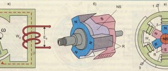
The operation of a synchronous machine is based on the phenomenon of electromagnetic induction and consists of converting mechanical energy into alternating current electrical energy (generators) or alternating current electrical energy into mechanical energy (motors), i.e. the synchronous machine is reversible.
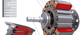
A synchronous machine consists of a stationary part - a stator, in the grooves of which a multiphase (usually three-phase) winding is located and a rotating part - a rotor with an excitation winding, powered from a direct current source (exciter) through slip rings and brushes. A synchronous machine can operate autonomously as a generator supplying a load connected to it, or in parallel with a network to which other generators are connected. When operating in parallel with the network, it can supply or consume electrical energy, i.e., operate as a generator or motor. When the stator winding is connected to a network with voltage U1 and frequency f1, the current passing through the winding creates a rotating magnetic field, the rotation frequency of which
n1 = 60×f1/p.
As a result of the interaction of this field with the excitation current Iв passing through the rotor winding, an electromagnetic torque M is created, which is rotating when the machine is operating in motor mode, and braking when operating in generator mode. In steady state, the rotor is stationary relative to the magnetic field and rotates at a rotation speed n1 = n2, where n2 is the rotor speed. Thus, in steady state, the rotor of a DC machine rotates at a constant frequency equal to the frequency of the rotating magnetic field.
Stator core assembled from sheet electrical steel, 2 - three-phase stator winding connected to the AC network, 3 - rotor core, 4 - phase rotor winding, 5 - slip rings for connection with a starting or control rheostat, 6 - short-circuited rotor winding.
MMF of windings of synchronous AC machines.
The magnetomotive force (MMF) of all alternating current windings located on the stator or rotor of an electrical machine must create a rotating magnetic field in its air gap. To do this, each of the windings, powered by a sinusoidally varying voltage, must have an MMF sinusoidally distributed in space, i.e., along the stator bore or along the rotor circumference. Failure to comply with these conditions, i.e. power supply from a non-sinusoidal voltage or a non-sinusoidal MMF distribution leads to the appearance of higher harmonics in the magnetic flux distribution curve, which leads to a deterioration in the energy performance of the machine.
We will assume that the windings receive power from a voltage source of a purely sinusoidal shape. Let's find out how the alternating current winding should be made so that the distribution of its MMF is sinusoidal.
MMF of concentrated winding. To establish the magnitude and nature of the distribution of the MMF of the winding, we first consider a two-pole machine with the simplest concentrated winding in which all the turns included in the AX phase are located in slots located in the center plane. When current passes from the beginning of phase A to its end X, a bipolar magnetic flux arises, the lines of force of which are directed as shown in the figure. Each power line of this flow is linked to all turns w of the coil of a given phase, therefore the MMF created by the coil Fк =∑i = iw. At the maximum value of the current in the coil, this MMF also has a maximum value: Fкm=Imw= = √2Iw.
Differences from DC machines
The fundamental design difference lies in the location of the winding. In AC systems it covers the stator, and in DC machines it covers the rotor. In both groups, electric motors differ in the type of current excitation - mixed, parallel and series. Today, AC and DC machines are used in industry, agriculture and in the domestic sphere, but the first option is more attractive in terms of its performance. AC generators and motors benefit from improved design, reliability and high energy efficiency.
The use of devices operating on direct current is common in areas where the requirements for precision control of operating parameters come to the fore. These can be traction mechanisms of transport, processing machines and complex measuring instruments. In terms of performance, DC and AC machines have high efficiency, but with different possibilities for technical and design adjustment to specific application conditions. Working with constant current gives you more control over speed, which is important when servicing servo motors and stepper motors.
Universal brushed motor
In general, the concept of a commutator motor implies an electric motor that can not only convert electrical energy into mechanical energy, but also vice versa. In this type of AC motor, at least one winding must be connected to the commutator.
Commutator motor rotor
In commutator engines, the commutators perform two functions at once:
- winding switch;
- a sensor used to determine the position of the rotor.
There are two types of commutator motors. Their classification occurs depending on the type of food:
- DC power supply. Such motors have a high starting torque, the rotation speed is smoothly controlled, and the design of the drive itself is quite simple.
- Universal motors can operate when powered by alternating and direct electrical energy. The dimensions of the machine are relatively compact and easy to operate.
Within the framework of the topic, we are interested in a universal-type commutator motor.
The picture below shows this type of machine and its main parts. All other CDs look similar.
The excitation of such motors can be serial or parallel. Machines of the second type are already outdated and out of production, so we will not dwell on it. A diagram of connecting the motor with the collector is shown in the figure below.
The principle of operation of a commutator motor using alternating current is as follows: during a polarity change, the current in the stator and rotor windings also changes direction. This prevents the rotational moment from changing its direction.
Application of UKD
In the last century, universal motors were used in the design of household appliances, but today all modern manufacturers prefer to use brushless motors.
Here are the main disadvantages of such drives:
- efficiency is reduced;
- brush-collector units are characterized by increased formation of sparks, this affects the rapid rate of wear of the device, it can also be dangerous.
Both types of motors, DC and AC, are designed to perform the same function - converting electrical power into mechanical power. Nevertheless, their comparison makes sense; they are fundamentally different from each other on several points:
- food type;
- process of creation;
- control system.
The first point, nutrition, is the most important difference, which is clear even from the name of the machines. It is clear that AC drives power AC sources, and DC motors power DC sources (for example, batteries or power converters).
Electric drives with a direct current field contain brushes and commutators in their design, which complicates their maintenance and reduces their service life relative to, say, asynchronous units, which cannot be said about the latter. On the contrary, they are distinguished by their strength and durability.
Another fundamental difference between engines is speed control.
In DC machines, the speed of operation can be adjusted by changing the current in the rotor windings. In AC electric motors - by adjusting the rotation speed.
Reversing in motor operation is the process of changing armature rotation to opposite in DC machines, asynchronous and universal commutator motors. It is almost impossible to imagine engine operation without such a function. Without changing the direction of rotation of the rotor, the hoist, overhead crane, winch, elevators and all other mechanisms for lifting loads will not work.
We will consider below how to reverse in an AC motor.
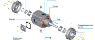
Asynchronous MPT device
For the technical basis of this device in the form of a rotor and stator, sheet steel is used, which is covered with an insulating oil-rosin layer on both sides before assembly. In low-power machines, the core can be made of electrical steel without additional coating, since the insulator in this case is the natural oxide layer on the metal surface. The stator is fixed in the housing, and the rotor is fixed on the shaft. In high-power asynchronous AC machines, the rotor core can also be attached to the housing rim with a sleeve mounted on the shaft. The shaft itself must rotate on bearing shields, which are also fixed to the base of the housing.
The outer surfaces of the rotor and the inner surfaces of the stator are initially provided with slots to accommodate the winding conductors. In the stator of AC machines, the winding is often three-phase and connected to the corresponding 380 V network. It is also called primary. The rotor winding is made similarly, the ends of which usually form a connection in a star configuration. Slip rings are also provided, through which a rheostat for adjustment or a three-phase starting element can additionally be connected.
It is also important to note the parameters of the air gap, which serves as a damper zone that reduces noise, vibration and heating during operation of the device. The larger the car, the larger the gap should be. Its size can vary from one to several millimeters. If it is structurally impossible to leave enough space for the air zone, then an additional cooling system for the installation is provided.
Peculiarities
According to the method of interaction between the rotor and the rotating magnetic field, devices are divided into two types - synchronous and asynchronous. In the first case, the rotation speeds of the field and the rotor are the same, in the second they are different.
Synchronous electric
Installations of this type are equally widely used as engines and generators.
Similar machines are used in all power plants. The rotor has its own magnetic poles. The rotor is an electromagnet at Ipost from a third-party source, less often a permanent magnet. Third party source Ipost. Usually there is a generator mounted on the machine shaft. But in some cases, a battery is also used.
Rotation is caused by the interaction of the rotating magnetic field of the stator and the rotor's own field. The first carries the second along with it, forcing the moving element to rotate at the same speed (motor mode). If you rotate the rotor by an external mechanical force, a 3-phase voltage will be obtained at the terminals of the stator winding (generator mode).
Asynchronous electrical
This device is mainly used as a motor. Compared to synchronous, it has a simpler design, which explains its widespread use. The rotor does not have its own magnetic poles, since its magnetic field is induced (for synchronous ones it is its own).
Asynchronous machines are divided into two types:
- collector;
- brushless.
The former are more diverse in characteristics, but due to the presence of such an expensive and unreliable unit, which is the collector, their scope of use is limited.
Brushless devices are the most common; they are divided into two types:
- with squirrel-cage rotor;
- with a wound rotor.
The winding of the first is a cage of copper or aluminum rods in the shape of a squirrel wheel, while the body of the element itself is made of ferromagnetic steel and represents a core.
Together, the rotor and stator cores form a magnetic circuit, and the windings on them operate like transformer ones:
- in the stator windings, when its terminals are connected to 3-phase voltage, a rotating magnetic field is formed, as described above;
- for the rotor, the rotating magnetic field moving relative to it is variable, which is why in its winding, according to the law of electromagnetic induction, an emf is induced and a current arises;
- it creates a magnetic field in the rotor winding that interacts with the stator field. In other words, an Ampere force acting on the rotor rods arises. It begins to rotate following the stator field.
It is obvious that the rotor rotation speed V cannot be equal to the analogous stator field parameter V0, since under such conditions the latter will no longer be variable for the rotor winding.
That is why this motor is called asynchronous. If, during rotation, the rotor overtakes the stator field, the machine switches to generator mode. The difference between V and V0 is characterized by the slip coefficient S = (V0 – V) / V0.
Squirrel cage rotor
Squirrel-cage motors have three disadvantages that limit their scope of application:
- small starting torque: when activated, the poles of the magnetic field induced in the rotor are under the poles of the rotating field of the stator;
- high starting current: 5-15 times higher than operating current;
- If a load on the shaft exceeds the maximum torque, the engine stops.
The wound rotor winding is designed similar to the stator winding. At the moment of start-up, an external resistance is connected to it, causing the relative position of the magnetic fields of the moving and stationary elements to change - the poles of one are brought out from under the poles of the other. A high starting moment occurs.
Operating principle of asynchronous MPT
In this case, the three-phase winding is connected to a symmetrical network with three-phase voltage, as a result of which a magnetic field is formed in the air gap. Regarding the armature winding, special measures are taken to achieve a harmonic spatial field distribution for the damper gap, which forms a system of rotating magnetic poles. According to the principle of operation of an alternating current machine, a magnetic flux is formed at each pole, which crosses the contours of the winding, thereby provoking the generation of electromotive force. A three-phase current is induced in the three-phase winding, providing torque to the motor. Against the background of the interaction of the rotor current with magnetic fluxes, an electromagnetic force is formed on the conductors.
If the rotor, under the influence of an external force, is set in motion, the direction of which corresponds to the direction of the magnetic field flows of the alternating current machine, then the rotor will begin to overtake the rate of rotation of the field. This occurs when the stator speed exceeds the rated synchronous frequency. At the same time, the direction of movement of electromagnetic forces will be changed. This creates a braking torque with reverse action. This operating principle allows the machine to be used as a generator operating in the mode of delivering active power to the network.
Basic information, scope of application
AC electric motors are divided into synchronous and asynchronous.
Synchronous electric motors are motors whose rotation speed is constant relative to the mains frequency; For asynchronous motors the ratio is not constant. The rotation speed of asynchronous motors varies depending on the load.
Asynchronous motors can have a converter device in the form of a commutator (commutator machines) or be without a commutator (no commutator).
The performance of electric motors is determined by the basic energy processes occurring within them (motor, generator, brake and converter), and the performance must be quantified. The quantitative operating mode is characterized by a number of electrical and mechanical variables: currents, voltage, power, speed and others. The electric motor is designed to operate under certain external conditions with certain parameter values (currents, voltage, power, etc.), operating for a certain and sufficiently long time.
The specified values of the various values that determine the operating mode of the engine are called nominal values, and the mode is called nominal.
The main ratings are indicated on the dedicated motor panel.
If the engine operates in a mode similar to the rated one, with a value different from the rated mode, but does not lead to a decrease in the reliability of the engine, then this is normal operation, otherwise it is abnormal operation.
All permissible normal and non-standard operating modes are clearly defined in GOST, technical specifications and operating instructions.
Among AC electric motors, the most common are asynchronous electric motors with a three-phase symmetrical winding on the stator, which is powered by an alternating current network, and with a three-phase or multiphase winding on the rotor. Induction motors are used primarily as motors, while synchronous motors are used primarily as generators since an electric motor can operate in either motor or generator mode.
Low-power induction motors are often single-phase, so they can be used in devices powered by a two-wire network. These motors are widely used in home appliances. Three-phase electric motors that operate on an industrial three-wire network are widely used in industry.
Most induction motors use a squirrel cage rotor. The squirrel-cage rotor is wound as a cylindrical cage made of copper or aluminum bars, which is inserted into the rotor core without insulation.
Asynchronous electric motors are produced by the domestic industry as a single series, covering all the necessary powers and speeds. Basically, motors for power supply are produced from a network with a frequency of 50 Hz. General purpose engines have a solid performance scale at all speeds.
The letter designations of all series of asynchronous motors contain the letter A (asynchronous), and the following letters indicate the design of the motor.
Since 1978, asynchronous motors with power from 0.06 to 400 kW at 500-3000 rpm have been produced mainly as the 4A series, which replaced the A2 series in this power range. 4A motors fully comply with IEC (International Electrotechnical Commission) recommendations regarding dimensions and installation and connection dimensions, which ensures the interchangeability of domestic electric motors with foreign-made electric motors.
Squirrel-cage asynchronous electric motors are mainly produced for general industrial use in moderate climatic conditions.
Nominal values of climatic factors are determined according to current GOSTs, but the altitude above sea level should not exceed 1000 m, dust content of the air environment should not exceed: 2 mg per cubic meter for engines in a protected design and 10 mg per cubic meter for engines in a closed blowing design (environment not is explosive and does not contain aggressive gases and vapors that destroy metals, insulation and conductive elements).
Motor ratings refer to continuous operation when connected to a 50 Hz mains supply.
In order to protect the environment, engines are produced in two versions: protected (1P23) and closed (1P44).
The engines have a standard power scale that applies at all speeds: 0.06; 0.09; 0.12; 0.18; 0.25; 0.37; 0.55; 0.75; 1.1; 1.5; 2.2; 3.0; 4.0; 5.5; 7.5; 11.0; 15.0; 18.5; 22; thirty; 37; 45; 55; 75; 90; 110; 132; 160; 200; 250; 315; 400 kW.
The height scale of the rotation axes (above the base plate) complies with IEC recommendations: 50; 56; 63; 71; 80; 90; 100; 112; 132; 160; 180; 200; 225; 250; 280; 315; 355 mm.
When marking motors, the serial number is indicated by a number followed by the motor number, for example A (asynchronous); then the engine version is indicated (for example): H - protected version); then indicate the material from which the engine frame and panels are made (A - aluminum frame and panels, X - aluminum frame and cast iron panels); then 50-355 - height of the axis of rotation; S, L, M - mounting dimensions along the length of the frame; A,B — the length of the magnetic core is indicated (A is the first length, the second length is B).
The number of motor poles is also indicated: 2, 4, 6, 8, 10, 12; climatic design, taking into account the possibility of overheating of the motor during operation and damage to its insulation (U - temperate climate, C - northern, T - tropical), then the placement category is indicated by a number according to the standard (for example - 3).
For example: 4AA56A2U3 - electric motor of series 4, asynchronous, closed design, frames and panels made of aluminum, with a height of 56 mm from the axis of rotation, magnetic wire of the first length, bipolar, for areas with a temperate climate, 3 placement categories.
Motors with a power of 0.12 ... 0.37 kW operate at a voltage of 220 ... 380 V, 0.55 ... 110 kW - at a voltage of 220 ... 380 and 380 ... 680 V, power 132 ... 400 kW at a voltage of 380 ... 680 V.
In addition to the basic version, the series has a number of electrical modifications and several special versions: chemically resistant, moisture resistant at 60 Hz and others. The standard sizes of all modified and specialized versions correspond to the standard sizes of the corresponding engines of the basic version. The series segment has a continuous power scale: 200; 250; 320; 400; 500; 630; 800; 1000; 1250 kW.
For each size there are 2-3 motor options depending on the length of the magnetic wire.
In accordance with the method of protection against environmental influences, the motors have two options: splash protection (provides protection against drops at an angle of 60 degrees to the vertical (motors are designated A2); enclosed motors - provide protection against solid bodies with a diameter of at least 1 mm and splashing water in any direction (motors are designated AO2).
Synchronous motors are electrical machines with two windings, one winding of which is connected to the network at a constant speed, and two windings are excited by direct current, while the rotor speed does not depend on the load.
Used as motors in large installations (piston compressor drive, air pipeline, etc.), mainly used as generators.
Rated values for synchronous motors: mechanical power on the motor shaft kW; Power factor; efficiency; stator winding phase diagram; stator network voltage V; stator rotation speed (rpm); stator current frequency Hz; stator network current A; excitation voltage and winding current.
Each engine is marked. On the body of each engine, the plate of which indicates: the trademark of the manufacturer; engine type indicating climatic characteristics and category; engine serial number; nominal operating mode; rated power, kW; pressure, V; electrical power, A; rotation speed, rpm; excitation system; parallel winding voltage, V; weight; year of issue; standard
For explosion-proof motors, the Explosion Protection Symbol (EPG) must be placed in a visible position and the grounding markings must be located near the grounding terminals.
AC motors have found the widest application in industry; they are used to drive high-speed mechanisms, to drive pumps, fans, rolling mills, etc. Electric motors are used in many industries.
Design and principle of operation of synchronous MPTs
In terms of design and stator location, a synchronous machine is similar to an asynchronous one. The winding is called an armature and is made with the same number of poles as in the previous case. The rotor has an excitation winding, the energy supply of which is provided by slip rings and brushes connected to a direct current source. By source we mean a low-power generator-exciter installed on one shaft. In an AC synchronous machine, the winding acts as a primary magnetic field generator. During the design process, designers strive to create conditions so that the inductive distribution of the excitation field on the stator surfaces is as close to sinusoidal as possible.
At increased loads, the stator winding forms a magnetic field with rotation in the direction of the rotor with a similar frequency. In this way, a single rotation field is formed, in which the stator field will influence the rotor. This design of AC machines allows them to be used as electric motors, if a three-phase current supply to the synchronous winding is initially provided. Such systems create conditions for coordinated rotation of the rotor at a frequency corresponding to the stator field.
Design, principle of operation and connection of AC electric motors
AC motors are electrical devices that convert electrical energy into mechanical energy. Electric motors are widely used in many industries to drive all kinds of machines and mechanisms. Without such equipment, the operation of washing machines, refrigerators, juicers, food processors, fans and other household appliances is impossible.
According to the principle of operation, AC electric motors are divided into synchronous and asynchronous. Asynchronous AC electric motors are most often used in industry.
It is worth considering the design of an asynchronous AC electric motor.
This type of electric motor consists of main parts - a stator and a rotor. In modern asynchronous electric motors, the stator has implicit poles.
In order to minimize losses from eddy currents, the stator core is made of an appropriate thickness of sheets of electrical steel that have been stamped. A winding of copper wire is pressed into the stator slots. The stator phase windings of the device can be connected in a star or delta. In this case, all the beginnings and ends of the pressed-in electric motor windings are brought out onto the housing - into the terminal box. Such a device for the stator of an electric motor is justified, since it makes it possible to switch its windings to different standard voltages. The stator core is pressed into a cast iron or aluminum housing.
The rotor of an asynchronous motor also consists of stamped sheets of electrical steel, and windings are placed in all its grooves.
Taking into account the rotor design, asynchronous electric motors are divided into devices with a squirrel cage rotor and a wound rotor.
The squirrel-cage rotor winding, made of copper rods, is placed in the slots of the rotor. In this case, all ends of the rods are connected using a copper ring. This winding option is considered a “squirrel cage” winding. It is worth noting that the copper rods in the rotor slots are not insulated. In many asynchronous electric motors, the “squirrel cage” is replaced by a cast rotor. The rotor is pressed onto the motor shaft and is one piece with it.
Synchronous electric motors are installed in various power tools, vacuum cleaners, and washing machines. On the body of an AC synchronous electric motor there is a pole core in which the windings are located. The field windings are also wound on the armature. Their leads are soldered to all sectors of the current collector, to which voltage is applied when using graphite brushes.
The operating principle of an AC electric motor is based on the application of the law of electromagnetic induction. When an alternating electric current interacts in a conductor and a magnet, continuous rotation can occur.
In a synchronous electric motor, the armature rotates synchronously with the electromagnetic field of the pole, while in an asynchronous electric motor the rotor rotates behind the rotating magnetic field of the stator.
For an asynchronous electric motor to operate, it is necessary that the rotor of the device rotates at a slower pace than the electromagnetic field of the stator. When current is supplied to the stator winding, an electromagnetic field arises between the stator and rotor cores, which induces an emf in the rotor. A rotating moment occurs and the motor shaft begins to rotate. Due to bearing friction or a certain load on the shaft, the rotor of an induction motor always rotates at a slower pace.
The operating principle of an asynchronous AC electric motor is that the magnetic poles of the device constantly rotate in the windings of the electric motor and the direction of the current in the rotor is constantly changing.
The rotor speed of an asynchronous electric motor depends on the total number of poles. In order to reduce the rotor speed in such a motor, it is necessary to increase the total number of poles in the stator.
In synchronous electric motors, the torque in the device is created by the interaction between the current in the armature winding and the magnetic flux in the field winding. When the direction of alternating current changes, the direction of the magnetic flux in the housing and armature simultaneously changes. With this option, the rotation of the armature will always be in one direction. It is noteworthy that the smooth regulation of the rotation speed of such electric motors is regulated by the magnitude of the supplied voltage, using a rheostat or variable resistance.
Depending on the network voltage, the stator phase windings of an asynchronous electric motor can be connected in a “star” or “delta” configuration. The circuit of an alternating current electric motor, when connected to a network with a voltage of 220 Volts, the windings are connected in a triangle, and when connected to a network of 380 Volts, the winding circuit has the shape of a star. To place an order, call the managers of the Kabel.RF® company by phone or send a request by email indicating the required electric motor model, purposes and operating conditions. The manager will help you choose the right brand, taking into account your wishes and needs.
Salient-pole and non-salient-pole synchronous machines
The main difference between salient pole systems is the presence of protruding poles in the design, which are attached to special shaft protrusions. In typical mechanisms, fixation is performed using T-shaped tail fasteners to the crosspiece rim or shaft through a sleeve. In the design of low-power AC machines, the same problem can be solved by bolted connections. The winding material is strip copper, which is wound onto an edge, insulated with special gaskets. The terminals with poles in the grooves house the winding rods for starting. In this case, a high resistivity material like brass is used. The winding contours at the ends are welded to the short-circuiting elements, forming common rings for a short circuit. Salient-pole machines with a power potential of 10-12 kW can be made in the so-called reversed design, when the armature rotates and the poles of the inductor remain stationary.
For non-salient pole machines, the design is based on a cylindrical rotor made of steel forging. The rotor contains grooves for forming an excitation winding, the poles of which are designed for high rotation speeds. However, the use of such a winding in electrical machines with high-power alternating current is impossible due to the high degree of rotor wear under harsh operating conditions. For this reason, even in medium-power installations, high-strength components made from solid forgings based on chromium-nickel-molybdenum or chromium-nickel steels are used for rotors. In accordance with the technical requirements for strength, the maximum diameter of the working part of the rotor of a non-salient-pole synchronous machine cannot be higher than 125 cm. This explains the unusual form factor of the rotor with an elongated body, although there are restrictions on this parameter associated with increased vibrations for too long elements. The maximum rotor length is 8.5 m. Non-salient-pole units used in industry include various turbogenerators. With their help, in particular, they connect the operating torques of steam turbines with thermal power plants.
Electric cars. To help the student
| Degree of sparking (commutation class) of DC electrical machines | |
| Sparking degree (switching class) Characteristics of sparking degree | Commutator and brush condition |
| 1 No sparking (dark switching) | No blackening on the commutator or carbon deposits on the brushes |
| 1¼ Weak spot sparking under a small part of the brush | Same |
| 1½ Weak sparking under most of the brush | The appearance of traces of blackening on the commutator, which can be easily removed by wiping the surface of the commutator with gasoline, as well as traces of carbon deposits on the brushes |
| 2 Sparking under the entire edge of the brush. Allowed only for short-term load shocks and overloads | The appearance of traces of blackening on the commutator, which cannot be eliminated by wiping the surface of the commutator with gasoline, as well as traces of carbon deposits on the brushes |
| 3 Significant sparking under the entire edge of the brush with flying sparks. Allowed only for moments of direct (without rheostat stages) switching on or reversing machines, if the commutator and brushes remain in a condition suitable for further operation | Significant blackening on the commutator, which cannot be eliminated by wiping the surface of the commutator with gasoline, as well as scorch and destruction of the brushes |
Note. At nominal operating conditions of the machine, sparking should not exceed a degree of 1½ . The reasons that cause sparking on the collector are very diverse, so if the sparking goes beyond the permissible limits. It is necessary to ensure that the brushes evenly cover the surface of the commutator, which contributes to uniform wear of the commutator. The surface of the brushes should be shiny and the entire surface should be adjacent to the commutator. Chipped brushes are not acceptable. All collector plates must be the same color. If some plates have a lighter shade, this indicates more intense wear. Sparking of DC machine brushes is discussed here. 5. It is necessary that when starting three-phase asynchronous motors with a squirrel-cage rotor directly connected to the network, the voltage drop in the supply network does not exceed permissible values. For this purpose, when determining the maximum permissible engine power, it is advisable to use the table data:
| Maximum permissible power of an asynchronous motor with a squirrel-cage rotor when starting it directly connected to the network | |
| Power supply | Maximum motor power |
| Transformer feeding the power network | 20% of transformer power for frequent starts, 30% for rare starts |
| Transformer feeding power and lighting networks | 4% of transformer power with frequent starts, 8% with rare starts |
| Low power power plant | 12% of power plant capacity |
| Transformer-motor block | Up to 80% of transformer power |
| High voltage network | No more than 3% of three-phase short circuit power at the point of connection of the electric motor |
Features of vertical hydro generators
A separate class of salient-pole synchronous MPTs provided with a vertical shaft. Such installations are connected to hydraulic turbines and selected according to the power of the flows being served according to the rotation frequency. Most AC machines of this type are low-speed, but have a large number of poles. Among the critical working components of a vertical hydraulic generator, we can note the thrust bearing and thrust bearing, which bear the load from the rotating parts of the engine. In particular, the pressure from the flow of water that acts on the turbine blades is also applied to the thrust bearing. In addition, a brake is provided to stop rotation, and the working structure also contains guide bearings that absorb radial forces.
At the top of the machine, along with the hydraulic generator, auxiliary units can be placed - for example, a generator exciter and a regulator. By the way, the latter is an independent alternating current machine with windings and poles of permanent magnets. This installation provides power to the motor to provide the automatic governor function. In large vertical hydrogen generators, the exciter can be replaced by a synchronous generator, which, together with exciter units and mercury rectifiers, provides energy supply to power devices that serve the working process of the main hydro generator. The machine's vertical shaft configuration is also used as a drive mechanism for high-power hydraulic pumps.
Collector MPT
The presence of a collector unit in the MPT design is often determined by the need to perform the function of converting the rotational speed in the electrical connection of different-frequency circuits on the rotor and stator windings. This solution allows you to provide the device with additional operational properties, including automatic regulation of operating parameters. AC commutator machines that are connected to three-phase networks receive three brush fingers in each double-pole segment. The brushes are connected to each other in a parallel circuit using jumpers. In this sense, commutator MMTs are similar to direct current electric motors, but differ from them in the number of brushes used on the poles. In addition, the stator in this system may have several additional windings.
The closed armature winding when using a commutator with three-phase brushes will be a three-phase complex winding with a delta connection. During the rotation of the armature, each phase of the winding maintains a constant position, but the sections alternately move from one phase to another. If an AC commutator machine uses a six-phase set of brushes shifted by 60° relative to each other, then a six-phase winding is formed with a polygon connection. On the brushes of a multiphase machine with a commutator group, the current frequency is determined by the rotation of the magnetic flux with respect to the stationary brushes. The direction of rotation of the rotor can be either counter or coordinated.
Direct current
DC motors appeared at the end of the 19th century. With some modifications they are still used today and they are popular. For example, vibration in a modern smartphone is provided by a DC motor, very small and with a power of milliwatts, but still. Most toys also have such engines. But this does not mean that they are not used in serious technology, just as they are used. The most powerful ones are used as traction units on electric locomotives. Their power amounts to hundreds of kilowatts (more than 800), and they are powered by a voltage of 1.5 kV.
Types of DC motors
Collector
A commutator DC motor, like all others, consists of a stationary (stator) and a moving (armature) part. The stator has magnetic poles. For low-power models, permanent magnets are installed; for powerful ones, windings are added (called excitation windings), which enhance the magnetic field.
The rotor is a magnetic circuit made of metal plates, in the grooves of which turns of copper wire are laid - rotor windings. The ends of the rotor windings are brought out to the collector, which consists of copper plates in the form of cylinder sectors. The plates are isolated from each other and from the shaft on which they are mounted. The ends of the windings are brought out to the collector plates. The second part of the commutator unit is graphite brushes with a brush holder. The brushes are pressed against the commutator plates, but do not interfere with the rotation of the armature.
Commutator-type DC motor design
Voltage is applied to the brushes. At a certain point in time, they have contact with a certain pair of plates on the commutator (rarely there are four brushes). This pair of plates is connected to the rotor windings, that is, power is supplied to the winding through the brushes. A magnetic field arises around the armature, which interacts with the magnetic field of the stator. The resulting vector of this interaction “pushes” the armature, causing it to rotate.
The shaft rotates, the brushes contact another pair of plates, transferring potential to other windings, which pushes the armature further. This is how a brushed DC motor works, and in more detail in the previous article.
Universal
Most household appliances that operate on mains power use a universal commutator motor. Its differences from those described above are insignificant. How can the same design work on both direct and alternating voltage? This is all due to the fact that in this machine the magnetic fields of the poles and rotor windings interact. Everyone knows that changing the direction of rotation of the armature is simple: you need to change the polarity at the poles or at the rotor. What happens if you change them both here and there at once? Nothing. The anchor will continue to move in the same direction. This is the basis for the operation of a commutator electric motor running on alternating current.
Cross-section of a universal commutator motor
The field and armature windings are connected in series, so that the polarity of the power supply on them changes almost at the same time. The only thing that had to be changed in the universal engine was to make the armature core laminated. This is necessary to stabilize the interaction of the magnetic fields of the armature and poles (with the field windings).
Advantages, disadvantages, scope
Why are commutator motors used in most household and construction equipment? There are several reasons for this. First: they can accelerate to high speeds - up to 10 thousand rpm. Compared to 3 thousand rpm, which their closest competitors asynchronous develop, and this is very good. The second reason for their popularity is that they are easy to manage. The rotation speed directly depends on the applied voltage, and the torque on the armature current. Before the advent of semiconductors and the creation of frequency converters, this was the only type of electric motor that made it possible to easily and accurately control speed. The third reason for its widespread use is its simple design and relatively low price. Fourth, they can have good torque even at low speeds.
One of the popular types of electric motors is a commutator motor.
All these properties have determined a wide range of applications for DC motors. They are found on washing machines, drills, mixers, etc. Wherever high speeds are required, the ability to smoothly adjust, good torque.
But the presence of brushes that spark and wear out makes its own adjustments. This unit requires constant maintenance; the brushes often have to be replaced and the commutator cleaned. In addition, it is the cause of two more unpleasant moments. The first is noisy work. For construction equipment or industrial equipment this may not be very critical, but for household equipment it is a significant disadvantage. The second trouble is that the brushes jump from one pair to another, so the current consumption turns out to be pulsed, which has a bad effect on the power parameters and creates radio interference. This has an impact on radio-controlled devices operating nearby. These are not only toys, but also various types of remote controls. To smooth out these jumps, capacitors are placed at the input; they smooth out the ripples and remove interference.
Valve motors
These motors are also called switched reluctance motors, brushless motors or brushless motors. There are two types of valve motors - “regular” and self-excited. Moreover, they differ in structure and functions.
Fan motors, regardless of type, are electronically controlled
Switched reluctance motor
If we compare types of electric motors by size, valve motors will be the smallest. What is typical is that they operate from direct current, and the stator windings are powered by it; the rotor does not have windings, but is made of permanent magnets. Moreover, both the rotor and stator have a gear structure. The “kit” includes a hall sensor, a small modern controller that detects the position of the rotor and, depending on its position, supplies power to one or another pair of windings on the stator. That is, the valve motor is controlled using an electronic device.
Design of a brushless electric motor
The principle of operation is probably already clear. Power is supplied to one pair of windings, and a magnetic field appears around it. The nearest pole of the magnet is attracted to this field. Next, the power switches to the next pair of windings, and the magnet is attracted there. This is how the rotor rotates. The faster the power switches, the faster the rotor speed. As you can see, no brushes, only magnetic induction. This is the main plus, and the minus is the “pulsating” nature of the torque. Therefore, switched induction motors are not used in transport; few people will like it if the wheels turn jerkily. Nevertheless, considering these types of electric motors, we come to the conclusion that this one has four significant advantages: simplicity of design, good speed control, absence of a commutator, and the fourth - small dimensions. All this allows them to replace asynchronous engines in some cases.
With independent excitation
This type of electric motor is worth highlighting separately, since it differs significantly both in design, characteristics and scope of application. Let's start with the fact that the rotor consists of two separate magnetic packages, spaced at some distance from each other. The poles of the two packages are oriented so that the resulting torque is zero (matched position). The field winding is attached to the stator, although it is wound around the rotor, but it does not touch it. The stator magnetic system is also assembled from metal plates. Three-phase distributed in nature, three phase windings offset relative to each other by 120°. The stator winding is slightly larger or equal in size to the assembled rotor (both packages are covered by a magnetic field).
Self-excited switched induction electric motor
Power is supplied to one of the stator windings. The induced field in the rotor rotates it to match the stator field. Moreover, the field is simultaneously induced in two packets, so the movement is not as jerky as in the previous model. The power switches to the next winding and rotation continues.
What is good about this type of electric motor? There are many advantages. It is easy to control the rotation speed, like synchronous machines with an excitation winding, vector control is available. You can increase or decrease the speed, adjust the torque. It does not contain magnets, which cost a lot and can even become demagnetized. And one more plus, there is no commutator or brushes. There is still a minus. This type of electric motor cannot be powered directly from the network - a converter is required. And yet, it has a more complex design than the option described above. But the torque is smoother and almost linear.
Application of MPT
Today, MPTs are used wherever the generation of mechanical or electrical energy is required in one form or another. Large productive units are used in the maintenance of engineering systems, power stations and lifting and transport units, and low-power units are used in ordinary household appliances from fans to pumps. But in both cases, the purpose of alternating current machines is to generate sufficient energy potential. Another thing is that the design differences, the implementation of the internal configuration of the stator and rotor, as well as the control infrastructure are of fundamental importance.
Although the general design of the MPT for a long time retains the same set of functional components, increasing requirements for the operation of such systems force developers to introduce additional monitoring and control elements. At the present stage of technological development, especially in the context of the use of alternating current machines in the industrial sector, it is difficult to imagine the operation of such engines and generators without high-precision means of regulating operating parameters. For this, a variety of control methods are used - pulse, frequency, rheostat, etc. The introduction of automation into the regulatory infrastructure is also a characteristic feature of modern MPT operation. The control electronics are connected to the power plant on one side, and on the other to software controllers, which, according to a given algorithm, give commands to set specific parameters for the operation of the mechanism.