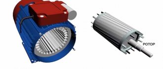
There are several classes of electrical converters, among which the so-called inductive analogues have found practical application. In them, energy conversion occurs due to the conversion of induction windings, which are an integral part of the unit itself. The windings are located on two elements - the stator and the rotor. So, what is the difference between a stator and a rotor (what are they and what are their functions?).
The simplest definition of the two parts of the converter is their functionality. Everything is simple here: the stator (of an electric motor or generator) is a stationary part, the rotor is a movable part. In most cases, the latter is located inside the former, and there is a small gap between them. There are so-called units with an external rotor, which is a rotating ring with a stationary stator inside.
Types of converters
Why is it so important to consider the types in order to understand how the stator of an electric motor differs from its moving part. The thing is that electric motors have a lot of design features, the same applies to generators (these are converters of mechanical energy into electrical energy, electric motors have the opposite functionality).
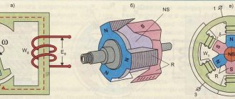
So, electric motors are divided into AC and DC devices. The former, in turn, are divided into synchronous, asynchronous and collector. For the former, the angular speed of rotation of the stator and rotor are equal. For the latter, these two indicators are unequal. In collector types, the design contains a so-called frequency converter and the number of phases of a mechanical type, which is called a collector. Hence the name of the unit. It is he who is directly connected to the windings of the motor rotor and its stator.
DC machines have the same commutator on the rotor. But in the case of generators, it performs the functions of a converter, and in the case of electric motors, it functions as an inverter.
If an electric unit is a machine in which only the rotor rotates, then its name is one-dimensional. If two elements rotate in opposite directions at once, then this apparatus is called two-dimensional or birotative.
Features of the asynchronous motor of the angle grinder
Almost all electrical appliances used in everyday life use an asynchronous electric motor.
An important advantage of this type of motor is that when the load on it changes, the speed does not change. This means that if, for example, you cut stone for a long time and without stopping with a household grinder, there will be no noticeable external signs of engine overload. The disk rotation speed will be constant, the sound will be monophonic. Only the temperature will change, but this may not be noticed if your hands are wearing gloves.
If you are not careful, an advantage can turn into a disadvantage. Asynchronous motors are very sensitive to overheating; a significant increase in operating temperature entails melting of the insulation on the rotor windings. At first, the motor will work intermittently, and then - when an interturn short circuit occurs - the motor will stop completely. If you overheat the grinder's engine several times, it is most likely that the anchor will melt. In addition, the high temperature causes the contacts connecting the wires of the primary winding to the collector to become unsoldered, which leads to an interruption in the supply of electric current.
Asynchronous electric motors
To understand the concepts of a motor rotor and its stator, it is necessary to consider one of the types of electrical converting machines. Since asynchronous electric motors are most often used in production equipment and household appliances, it is worth considering them.
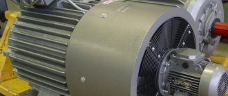
So, what is an asynchronous electric motor? This is usually a cast iron body into which a magnetic circuit is pressed. It contains special grooves into which the stator winding, assembled from copper wire, is placed. The grooves are shifted relative to each other by 120º, so there are only three of them. They form three phases.
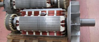
The rotor, in turn, is a cylinder assembled from steel sheets (stamped electrical steel) and mounted on a steel shaft, which in turn is installed in bearings when assembling the electric motor. Depending on how the phase windings of the unit are assembled, the motor rotors can be phase or squirrel-cage.
- A phase rotor is a cylinder on which coils are assembled, shifted relative to each other by 120º. At the same time, three slip rings are installed in its design, which do not come into contact with the shaft or with each other. The ends of three windings are connected to the rings on one side, and graphite brushes on the other, which are located in sliding contact relative to the rings. An example of such a machine is crane electric motors with a wound rotor.
- The squirrel-cage rotor is assembled from copper rods that fit into grooves. At the same time, they are connected with a special ring made of copper.
Best answers
Elektroburatino:
You see, dear Sergey XXX, the question, as I understand it, is a tricky one... Most likely, NOTHING!! ! This is the same name for a part of an electric current generator or an electric motor... I just don’t understand one thing - WHY ARE SUCH QUESTIONS NEEDED?? ? Do you really need answers to these questions? ? Or did you just want to flirt (make fun)?!..
Larisa Dementieva:
Is it true? The rotor is something that is in rotation, and the anchor forces it to remain in stagnation.
Vasya:
armature in DC motors, rotor in AC motors.
Sailor:
This is the name of one part that rotates inside the stator. Difference. There is no winding on the rotor, but there is one on the armature.
realist:
The rotor in DC electric machines is called an armature.
Amir Kstaubaev:
The rotor is the entire rotating part of the electric motor. engine (from the beginning of the motor shaft to the end of the shaft!!! and the armature is that part, round, where exactly the winding with steel plates goes where the EMF is formed!!!! (The rotor is the entire rotating part of the electric motor. Entirely. And the armature is that part of the rotor , where the winding of the electric motor is located in which the EMF is induced. In this photo, the armature along with the windings is indicated by the number four.)
Anatoly Lapshov:
unfortunately, the armature and the rotor are completely different parts, for some reason they don’t put a rotor on the electromagnet, and in non-rotor asynchronous motors there is a short-circuited armature, also now they call a die, but is it possible to cut a thread with a die without a tool? Yes, of course, people who studied in at the crossings it seems to them that all the same educated people were kicked out
Operating principle of the electric motor
- Detailed description of the operating principle of different types of electric motors:
- Operating principle of a single-phase asynchronous electric motor
- Operating principle of a three-phase asynchronous electric motor
- Operating principle of a synchronous electric motor
Classification of electric motors
| Rotating electric motor | ||||
| Self-switching | Externally switched | |||
| Mechanically switched (collector) | Electronically switched 1 (valve 2, 3) | Asynchronous electric motor | Synchronous motor | |
| Alternating current | Direct current | AC 4 | Alternating current | |
|
|
|
|
|
| Simple electronics | Rectifiers, transistors | More complex electronics | Complex electronics (CP) | |
- This category does not represent a separate class of electric motors, since the devices included in the category under consideration (BDDC, VRM) are a combination of a brushless motor, an electrical converter (inverter) and, in some cases, a rotor position sensor. In these devices, the electrical converter, due to its low complexity and small dimensions, is usually integrated into the electric motor.
- A valve motor can be defined as an electric motor that has a rotor position sensor that controls a semiconductor converter that performs coordinated commutation of the armature winding [5].
- A DC valve motor is a DC electric motor, the valve switching device of which is an inverter controlled either by the rotor position, or by the phase of the voltage on the armature windings, or by the position of the magnetic field [1].
- The electric motors used in BLDC and VRD are AC motors, and due to the presence of an electric converter in these devices, they are connected to a DC network.
- The stepper motor is not a separate class of motor. Structurally, it is a PMSM, SRD or hybrid SRD-PM.
- CMDC - commutator DC motor
- BLDC – brushless DC motor
- EP - electrical converter
- DPR - rotor position sensor
- VRD - switched reluctance engine
- ADKR - asynchronous motor with squirrel-cage rotor
- ADFR - asynchronous motor with wound rotor
- SDOV - synchronous motor with excitation winding
From simple inventions to the electric motor
After a number of his discoveries, J. Henry made a magnetic circuit with a coil, which was installed horizontally, like the beam of a laboratory scale. When the armature swung, the contacts attached to the ends of the rocker touched the terminals of two galvanic cells, which fed the coil with currents of different directions. While swinging, the rocker was attracted to two permanent magnets that were part of the system.
The installation could operate continuously, imparting 75 swings to the armature per minute. This is how one of the first designs of a reciprocating electric motor arose. And turning it into a rotational motion engine at that time was not difficult. It is worth noting that machines with reciprocating motion were not popular at that time, since electric motors with a rotating armature were considered technologically more convenient.
Later came the era of three-phase alternating current. The rotating components of an AC motor are no longer called an armature. The rotating magnetic field began to be called a vortex, and the rotating part - a rotor. However, in DC machines the terminology has been preserved. The armature rotated, and the pole piece was called a shoe.
Today, multiphase linear electric motors for monorail trains are becoming widespread. A tightly attached monorail is used as a rotor, and windings that are installed on the magnetic core of fast-moving electric trains serve as the stator.
The company ZAO PromElektroRemont has all the necessary certificates for the provision of such work as:
- Repair and rewinding of electrical equipment;
- Repair of welding transformers;
- Repair of pumps, including deep ones;
Other events
Types of electric motors
Commutator motors
A commutator machine is a rotating electrical machine in which at least one of the windings involved in the main energy conversion process is connected to a collector [1]. In a commutator motor, the brush-commutator assembly serves as a rotor position sensor and a current switch in the windings.
Universal electric motor
DC brushed motor
Brushless motors
Brushless motors may have slip rings with brushes, so there is no need to confuse brushless and brushless motors.
A brushless machine is a rotating electrical machine in which all electrical connections of the windings involved in the main energy conversion process are carried out without sliding electrical contacts [1].
Asynchronous electric motor
Synchronous electric motor
Is it worth doing the rewinding yourself?
When repairing the stator of an asynchronous electric motor, which is most often used today in household and industrial appliances, an insufficiently experienced technician may encounter a number of difficulties. In this case, he can contact the service department, where specialists will perform rewinding in accordance with all the rules for a fee.
Rewinding electric motors, the price of which is currently set by service centers, will cost about 2-4 thousand rubles. However, for more powerful engines, prices increase significantly. The procedure can reach 135 thousand rubles. for rewinding large industrial motors.
Stator device
A commutator motor is a single-phase motor with series excitation of windings, designed to operate on AC or DC power. Therefore, it is also called a universal commutator motor (UCM).
Expert opinion
It-Technology, Electrical power and electronics specialist
Ask questions to the “Specialist for modernization of energy generation systems”
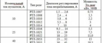
Brush 80 of all industrially produced electric motors are asynchronous, due to the numerous advantages of this type of drive. Ask, I'm in touch!
Basic parameters of the electric motor
Motor torque
Torque (synonyms: torque, torque, moment of force) is a vector physical quantity equal to the product of the radius of the vector drawn from the axis of rotation to the point of application of the force and the vector of this force.
,
- where M is torque, Nm,
- F – force, N,
- r – radius vector, m
,
- where Pnom is the rated power of the engine, W,
- nnom - rated rotation speed, min -1 [4]
Initial starting torque is the torque of the electric motor at start-up.
1 oz = 1/16 lb = 0.2780139 N (N) 1 lb = 4.448222 N (N)
torque is measured in ounce-force per inch (oz∙in) or pound-force per inch (lb∙in)
1 oz∙in = 0.007062 Nm (Nm) 1 lb∙in = 0.112985 Nm (Nm)
Motor power
Motor power is the useful mechanical power at the motor shaft.
Mechanical power
Power is a physical quantity that shows how much work a mechanism does per unit of time.
,
- where P is power, W,
- A – work, J,
- t—time, s
Work is a scalar physical quantity equal to the product of the projection of the force on the direction F and the path s traversed by the point of application of the force [2].
,
For rotational movement
,
- where is the angle, rad,
,
- where is the angular velocity, rad/s,
In this way, you can calculate the value of mechanical power on the shaft of a rotating electric motor
Electric motor efficiency
The efficiency of an electric motor is a characteristic of the machine’s efficiency in converting electrical energy into mechanical energy.
Comparison of characteristics of externally commutated electric motors
Below are comparative characteristics of externally commutated electric motors from the perspective of application as traction motors in vehicles.
| Parameter | ADKR | SDPMP | SDPMW | SRD-PM | SDOV |
| Consistent power throughout the entire speed range | |||||
| Efficiency (efficiency) over the entire operating range |
In accordance with the above indicators, a hybrid synchronous electric motor, namely a synchronous reluctance electric motor with built-in permanent magnets, is most suitable for use as a traction motor in the automotive industry (the choice was made for the BMW i3 & BMW i8 concept cars). The use of reactive torque provides high power in the upper speed range. Moreover, such an engine provides very high efficiency over a wide operating range [7]. |
Connection diagrams
The connection of the stator and rotor windings of an electric motor is carried out according to one of two schemes: “star” or “delta”. When using the first scheme, some ends of the stator windings are connected to each other, and the others are supplied with three-phase voltage (380 volts). At the same time, it is worth paying attention that a motor with windings connected in a star method has less power when compared with another method.
Delta connections are implemented by connecting all stator windings in series. That is, each winding is connected at its end to the beginning of the next coil. Switching engine components according to this scheme will provide an order of magnitude greater operating power, as full as possible. At the same time, the starting currents in such a circuit are quite high, which is why it is recommended to use a “star” to start the equipment, and then switch to a “delta” during operation.