Principle of operation
A megohmmeter is a useful invention that can be used to check the performance of the insulating layer in wiring. The device is classified as professional, but most modern models support several functions at once, for example, analyzing the state of the electrical network, checking the exact voltage, and so on. In this regard, many people want to purchase their own megohmmeter to use it for household tasks.
Using special probes, the device is connected to the line being measured and then started. Each device is equipped with a constant voltage source that generates high voltage to test insulation. As for the basic functions and set of calibration voltages, they differ depending on the specific model. If cheap options have only one operating mode, then more expensive ones are characterized by high performance and combined capabilities.
are currently available on the market :
- Older models equipped with a built-in dynamo. To start the device you need to turn a special handle.
- New devices with electronic circuitry. They are connected to a household electrical outlet or internal batteries, using them as a voltage source. Among the supported modes and functions there is not only monitoring of wiring insulation, but also assessment of current voltage, low-resistance resistance and other parameters. In fact, many models can replace a multimeter, since the range of calibration voltages is quite wide.
The calibrated voltage and its value are set using a special switch. For precise tuning, it is necessary to take into account the type of system that can be analyzed. The resulting measurements will be shown on the screen or corresponding scale. To simplify the process of studying the results, in pointer-type models the scale is calibrated in KOhm or MOhm.
The operating principle of the invention is based on Ohm's simple physical law: I = U / R.
Measuring insulation resistance with a megohmmeter. How to use a megohmmeter
HomeMiscellaneousProcedure for working with a megohmmeter
Despite the fact that the megohmmeter is considered a professional measuring device, in some cases it can also be in demand at home. For example, when you need to check the condition of electrical wiring.
Using a multimeter for this purpose will not allow you to obtain the necessary data; at most, it is capable of detecting the problem, but not determining its scale.
That is why measuring insulation resistance with a megohmmeter remains the most effective test method; this is described in detail in our article.
Design and principle of operation of a megohmmeter
The aging of electrical wiring insulation, like any electrical circuit, cannot be determined with a multimeter. Actually, even with a rated voltage of 0.4 kV on the power cable, the leakage current through microcracks in the insulating layer will not be so large that it can be detected by standard means. Not to mention measuring the resistance of intact cable insulation.
In such cases, special devices are used - megohmmeters, which measure the insulation resistance between the motor windings, cable cores, etc. The principle of operation is that a certain voltage level is applied to the object and the rated current is measured. Based on these two values, the resistance is calculated according to Ohm's law (I = U/R and R=U/I).
It is typical that megohmmeters use direct current for testing. This is due to the capacitance of the measured objects, which will pass alternating current and thereby introduce inaccuracies in the measurements.
Structurally, megaohmmeter models are usually divided into two types:
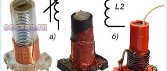
- Analogue (electromechanical) - old-style megohmmeters. Analog megohmmeter
- Digital (electronic) – modern measuring devices. Electronic megohmmeter
Let's consider their features.
Electromechanical megohmmeter
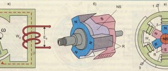
Let's consider a simplified electrical circuit of a megohmmeter and its main elements
Simplified diagram of an electromechanical megohmmeter
Designations:
- A manual DC generator, a dynamo is used as such. As a rule, to obtain a given voltage, the rotation speed of the hand generator handle should be about two revolutions per second.
- Analog ammeter.
- An ammeter scale calibrated to indicate resistance measured in kiloohms (kOhm) and megaohm (MOhm). The calibration is based on Ohm's law.
- Resistance.
- KOhm/Mohm measurement switch.
- Clamps (output terminals) for connecting test leads. Where “Z” is the ground, “L” is the line, “E” is the screen. The latter is used when it is necessary to check the resistance against the cable shield.
The main advantage of this design is its autonomy; thanks to the use of a dynamo, the device does not require an internal or external power source. Unfortunately, this design has many weaknesses, namely:
- To display accurate data for analog instruments, it is important to minimize the mechanical impact factor, that is, the megohmmeter must remain stationary. And this is difficult to achieve by rotating the generator handle.
- The displayed data is affected by the rotational uniformity of the dynamo.
- Often the measurement process requires the efforts of two people. Moreover, one of them performs purely physical work - he rotates the handle of the generator.
- The main disadvantage of the analog scale is its nonlinearity, which also negatively affects the measurement error.
Device and design
Most models of such measuring instruments include a DC generator, a measuring head, a switch, and current-limiting resistors. This unit provides switching of any resistor circuits that affect the output voltage and operating mode.
All components of the megohmmeter are combined in one housing with a durable dielectric coating. For convenient transportation, the device is equipped with a comfortable handle on which a portable generator handle is placed. To start the device, simply unfold the handle and start rotating.
You may be interested in: Selecting and connecting features of an energy meter
The operating principle of devices with internal or external power supply does not differ from mechanical models with a handle. To produce the required voltage, just press the corresponding button and hold it until the desired values are achieved. Some devices can output different voltage combinations with a few simple buttons.
Modern models have a more complex internal structure. In this regard, they can produce different voltages, from 100 to 2500 V. In addition, individual devices are able to work with several ranges at once, which makes them highly efficient.
Models that can detect the insulation of high-voltage industrial equipment are more productive than those devices that only work on household wiring. Naturally, their sizes are very different.
Danger of high voltages
The built-in generator is characterized by output power indicators that are enough not only to assess the condition of the insulation, but also to cause a serious burn. Because of this feature, only trained electrical technicians with at least group 3 access to such devices are allowed to use the device.
When taking measurements using increased voltage, you need to cover the area being tested, terminals and wires. To ensure protection, probes with characteristic insulation are used. On one side they are fixed to the wires, and the other part is equipped with safety rings. As a result, it prevents you from touching exposed areas and prevents possible electric shock.
To carry out measurements, such devices provide a special working area that does not conduct current and is a safe place to hold. To connect to the circuit, use an alligator clip with good insulation. Any other wires or stand-alone probes are not allowed. In addition, to increase the safety of the procedure, the area being tested must be isolated from strangers. This is especially important when checking resistance in long cables with a length of up to several kilometers.
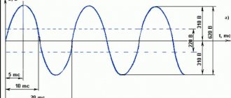
As for the induced voltage , it plays a significant role in the accuracy of the measurements. Electricity that passes through power transmission line wires is capable of creating a certain magnetic field, measured taking into account the sinusoidal law. If the cable has an impressive length, this voltage becomes very high.
Depending on this factor, the measurement accuracy varies significantly. This is explained by the fact that the magnitude and direction of the current passing through the device remain unknown. It occurs under the influence of induced voltage, and its indicators appear near the device’s own readings. As a result, the sum of two current quantities is displayed on the digital screen, and the task remains unsolved. Therefore, measuring insulation resistance in the presence of any type of voltage is a waste of time and effort.
You may be interested in this Device for an electrician: voltage tester
Measuring insulation resistance with a megohmmeter [edit | edit code]
The insulation resistance characterizes its condition at a given time and can vary from the influence of external conditions, since it depends on a number of factors, the main influencing factors being the temperature and humidity of the insulation at the time of measurement.
In GOST 183-74, standards for the permissible minimum insulation resistance are not standardized, since there are no absolute criteria for the minimum permissible insulation resistance. They are usually established in standards for specific types of machines or in technical specifications for products or materials with a mandatory indication of the temperature at which measurements must be carried out, and the method for recalculating the measured resistance, reduced to standard conditions, if the measurements were carried out at a different temperature of the windings.
Measuring the insulation resistance of windings establishes the possibility of testing insulation with operating high voltage without the risk of electrical breakdown of insulation that is serviceable but has high humidity.
The measurements are carried out with a megohmmeter, the test voltage of which is selected depending on the rated operating voltage of the insulation under test. For devices with a rated voltage of up to 500 V (660) V, 500 V megohmmeters are used, for devices with voltages up to 3000 V - 1000 V megohmmeters, for devices with a rated voltage of 3000 V and more - 2500 V megohmmeters and higher.
The degree of moisture content of the insulation is judged not only by the resistance value at the time of measurement, but also by the nature of the change in the megohmmeter reading during the measurement process, which is usually carried out within 1 minute. In this case, the readings of the device are recorded 15 s after applying the test voltage (time sufficient to establish the readings), this resistance is designated R15″ and at the end of the measurement - 60 s after the start – the designation R60″. The ratio of these readings R60″/R15″ is called the absorption coefficient
(KA). Its value determines the ratio of the polarization current to the leakage current through the dielectric - the winding insulation. With wet insulation, KA is close to 1. With dry insulation, the value of R60″ is 30-50% greater than the value of R15″.
The megohmmeter also measures the insulation resistance of thermal converters built into electrical machines and the insulation resistance of wires connecting the thermal converters to external terminals.
The insulation resistance of thermal converters is measured relative to the device body and relative to the machine windings. This insulation is not designed to operate at high voltages in the machine windings, so its resistance should be measured with a device with a rated voltage of no higher than 250 V.
In addition to the insulation resistance of the windings, when testing at the installation site of the machine, the insulation resistance of the bearings is also measured, which is installed to prevent the flow of bearing currents in machines with riser bearings [ clarify
] .
Thus, the insulation resistance of different windings of the same machine, having different rated voltages, for example, the stator and rotor windings of a synchronous motor, must be measured with different megohmmeters with different rated voltages, or with a megohmmeter with a switchable test voltage.
Electrical resistance can be measured with various instruments. The megohmmeter has become the most popular among such devices. Judging by the name of the device, it can be determined that its unit of measurement is megaohms. It is primarily used to measure large resistance values, electrical circuits , and dielectric insulation used for cables, wires , electric motors , transformers and other electrical installations.
To use a megohmmeter in work, you must first study its operating principle, design and technical parameters, since there are specific features when using such a device.
Kinds
There are two main types of megohmmeters, differing in the type of power source and measurement method.
Analog
Such devices are also called pointer devices. They have an individual dynamo, which is activated by turning the handle, as well as a graduated scale with a dial indicator. The measurement is carried out based on the magnetoelectric principle. The pointer is fixed on the same axis with a frame coil located in the magnetic field of a permanent magnet.
When current flows through the coil, it deflects by a certain angle, depending on the magnitude of the current flowing. This action occurs according to the law of electromagnetic induction. The pointer megohmmeter is unpretentious in operation, reliable, although it is considered an outdated device, has a large mass and significant overall dimensions.
Digital
Modern digital megohmmeters have a built-in powerful pulse generator operating on field-effect transistors . Such devices are equipped with an individual power source, in the form of an AC adapter that converts alternating current to direct current, or a rechargeable battery . The measurement is performed by a special amplifier by comparing the voltage drop in the circuit under test with a reference resistance.
Read also: DIY jigsaw table with drawings
The measurement results are displayed on a digital screen. It is possible to save the results in memory for future data comparison. The electronic megohmmeter is lightweight and small in size, allowing you to make many different electrical measurements. However, to work with such a device, highly qualified personnel are required.
Operating principle and device
The operation of a megohmmeter is to use Ohm's law , which is described by the formula: I = U / R , where I is the current, U is the voltage, and R is the resistance. The device of this device includes a calibrated voltage source, an ammeter and terminals to which special measuring probes are connected.
Older analog instruments have conventional hand-held generators with a crank to operate them, while newer models use external or internal power sources in the form of a battery or power supply. The amount of power at the generator output and the voltage can vary over a wide range, or be constant, depending on the design of the device. The megaohmmeter kit includes measuring probes, which consist of wires with tips: on one end of the probe there is a tip for insertion into the device socket, and on the other there is a “crocodile” for reliable contact.
Before measurement, the probes are inserted into the sockets on the device, then connected with crocodile clips to the object being measured. When performing a measurement, the generator generates high voltage by rotating the handle. Voltage is supplied to the object being measured, and the measurement results are displayed on the screen of a digital device or on the scale of a pointer megohmmeter.
How to use a megohmmeter correctly
During operation, the device produces high voltage that is dangerous to humans - from 500 to 2500 volts. Therefore, the use of the device must be approached with extreme caution. In industrial production, persons with an electrical safety group of at least third are allowed to work with it.
Before taking measurements, the circuits being tested should be de-energized. If measurements are planned to be made in an apartment, then you should turn off the circuit breakers in the distribution board, then turn off all connected devices in the apartment.
If groups of sockets are checked, then all inserted device plugs should be removed from them. When checking lighting circuits, it is necessary to unscrew the light bulbs, since they are not designed for such high voltage and can burn out. When testing the insulation of electric motors, they should also be disconnected from the network.
Next, the circuits being tested should be grounded. To do this, a stranded wire in insulation with a cross-section of more than 1.5 mm 2 is connected to the grounding bus, which is portable grounding.
Safety requirements
Even if you use a megohmmeter at home, before work you should study the requirements for safe work practices.
There are several basic rules:
- Probes should only be held by insulated handles limited by stops.
- Before connecting the probes to the circuit being measured, you should make sure that the voltage supply to the device is turned off and that there are no people near the line being measured who could accidentally become energized.
- The next step is to remove the residual voltage by touching a portable ground to the circuit being measured. Grounding is turned off only after installing the probes.
- After each measurement, it is necessary to remove residual voltage from the probes by connecting the probes to each other.
- After the measurement, grounding should be connected to the tested conductor to remove the residual charge.
- All work must be done with rubber gloves.
These simple rules must be followed, since the safety of people depends on it.
Rules for connecting probes
There are three sockets on the device body. They are designated by the symbols “ E ”, “ L ” and “ Z ”, which means screen, line and ground, respectively. The megaohmmeter kit contains three probes. On one of them, two tips are connected on one side. This probe is used when it is necessary to exclude leakage current, and is connected to the shielded sheath of the cable, if available. The remaining probes are inserted into the sockets corresponding to the markings of the probes with the same letters.
All probes have stops. When taking measurements, you should grasp the probes as far as they will go so as not to accidentally touch the live parts with your fingers.
If it is necessary to measure only the insulation resistance, without taking into account the screen, then two single probes are connected. Of these, one is inserted into the “ Z ” terminal, and the second into the “ L ” terminal. The second sides of the probes should be connected with “ crocodiles ”:
- To the wires being tested, if necessary, test for breakdown between the wires.
- To the grounding and current-carrying conductor, if you need to test the “ground fault”.
Usually, a check is made for insulation breakdown and the value of its resistance, and a check of the shielded sheath is rarely performed, since cables with a shield are almost never used in apartments. When using the device, the main rule is to remove the residual charge, as well as to be careful, as there is a danger of getting under high voltage.
Measurement procedure
- Before starting the measurement (using the indicator ), you should make sure that there is no voltage on the line being measured.
- Connect the ground.
- Set the voltage value with which the measurement will be made. It must be selected from the table, depending on the type of element being measured. The voltage is switched using a button or knob on the panel. There are also devices that operate with a fixed single voltage and do not require voltage setting.
- Connect the probes, following the safety rules discussed earlier.
- Remove grounding from the object being tested.
- Put the megohmmeter into operation. If it is electronic, then you should press the start button, which may be called “ test ”. If the megohmmeter is of an analog type with a dial indicator, then you need to rotate the dynamo handle for some time until the indicator on the device body lights up, indicating that the required voltage has been created. Digital megohmmeter at some point the readings on the display stabilize. The numbers will indicate the amount of resistance. If it is higher than the permissible norm, which is indicated in the table above, then everything is in order, if it is lower than the norm, then damage to the insulation of the object should be detected.
- After recording the readings, you should stop rotating the dynamo handle, or press the shutdown button on the digital device.
- Disable probes.
- Neutralize residual stress.
Read also: Voltage regulator on a microcontroller
How to check cable insulation
The most common test is to measure the insulation resistance of wires or cables. If you have the skill to work with a megohmmeter, then you can check a single-core cable very quickly, unlike a multi-core cable. The greater the number of cores, the longer the check will take, since each core needs to be checked separately.
The control voltage should be selected depending on the operating voltage of the cable. If it operates at a voltage of 380 or 220 volts, then the test voltage is set to 1000 volts.
When testing the insulation of a 1-core cable, we connect one probe to the core, and the other to the shielding shell, and apply voltage. If there is no screen, then the second probe needs to be connected to ground, and we apply voltage. If the measurement result is at least 500 kOhm, then the insulation is in good condition; if the resistance is less, then such a conductor cannot be used, since the insulation is damaged.
When testing a cable with several cores, testing is carried out separately for each core. At this time, the remaining wires are connected into one bundle. If it is necessary to check the breakdown to ground, then a ground wire is added to this harness. If there is armor or shielding, then they are also attached to this harness. In this common harness, it is important to ensure the quality of contact of the conductors.
The insulation of sockets is measured in the same way. Before checking, all devices are turned off, as well as the power in the distribution board. One probe is connected to ground, and the other to one phase. We set the control voltage on the device to 1000 volts and carry out the test. If the resistance is more than 500 kOhm, then the insulation is good. We also check all other wires.
Electrical resistance measurements can be performed with different instruments. Among them, a megohmmeter is quite often used, the name of which consists of three parts. "Mega" means million or 10 6 , "ohm" corresponds to resistance, and the particle "meter" is equivalent to the word "measure". Thus, the measuring range of this device is megaohms. Beginner electricians are recommended to study the principle of operation, design and technical characteristics of this measuring device before using a megohmmeter.
Taking measurements
It’s not at all difficult to take any measurement or figure out how to work with a megohmmeter. But with such an activity, it is important to follow a certain sequence of actions and correctly move from one stage to the next. Before you begin, you should read the instructions and complete the preparatory steps.
First of all , you will need to disconnect the circuit under test from the specified load . If we are talking about the insulating layer in home wiring, it is enough to disconnect the power using a switch or a twist-out plug. When measuring the cables of a socket group, plugs must be removed from all sockets. When working with wiring for lighting fixtures, you need to unscrew the light bulbs from all chandeliers, spotlights and other equipment. Only after this can the verification begin.
The next stage of preparation is connecting an autonomous grounding. It will be needed in order to relieve residual voltage in the circuit. To do this, a copper wire with a cross-section of 1.5 square is fixed to the main bus in the shield. The opposite end must be stripped of insulation, so it is attached to a dry stick.
The wire is fixed in such a way that the copper comfortably touches the conductors.
Safety requirements
If we are talking about taking measurements using a megohmmeter at any enterprise, then it must be carried out by a trained specialist with an electrical safety group of 3 and above. Even during a home examination, it is important to adhere to basic rules and comply with safety requirements. So, according to the established instructions, each work with a megohmmeter must be carried out taking into account the following rules:
- The work should only be done with dielectric gloves (unfortunately, most people often miss this rule, but this is a mistake).
- Before you start work, you need to prepare the line and make sure that there are no people near it. Plants and factories should display posters warning “do not start”, “caution, high voltage” and so on. When measuring a long line at home, you can adhere to a similar principle - it is advisable to place a sign about the danger on the shield. You also need to familiarize yourself with the first steps when receiving an electric shock.
- During operation, the probes must be kept in the insulation area. Often, the handle has finger rests that are protected from high voltages.
- After completing the calculations, you need to connect the probes by crossing their non-insulated areas. In this way, residual stress can be relieved. Some electronic devices support an automatic discharge function, where the residual voltage is discharged after each measurement. If such a function is not available, you will have to perform the procedure yourself.
When performing calculations, special attention must be paid to residual stress. If the tested line is too long, the charge will become impressive and can cause serious damage to a person.
How to ensure safe work with a megohmmeter
The work is performed exclusively with the help of serviceable megohmmeters (checked and tested in a metrology laboratory specially designed for this purpose). Verification allows the owner of the unit to have a special certificate, which gives a time-limited right to carry out work, that is, until a certain expiration date. After verification, the specialist applies a mark to the body of the device, indicating that the control verification has been carried out. The stamp contains the date and number of the inspector. The responsibilities of the owner of the megohmmeter include maintaining the integrity of the mark, since it is this that gives the right to carry out subsequent measurements. There is no mark, which means: the device is not working properly!
When performing several measurements in a row in a ten-core cable, you should always use portable grounding, and also remove the residual charge after each measurement. Fast and safe work with a megohmmeter is ensured by connecting one end of the grounding conductor to the ground loop until all work is completed. The second end of the conductor is attached to an insulating rod, which is designed for the convenience of repeated application of grounding in order to safely remove the residual charge.
Line connection
The standard package includes three probes with different characteristics and structures. One of them has two tips and is designed to combat leakage currents. On the top side of the device there are three sockets for connecting probes. Each of them is characterized by a corresponding letter marking:
- Z - for connecting protection grounding.
- L is the line that is being measured.
- E - screen (intended to eliminate leakage currents).
You might be interested in this: How to make a simple voltage regulator with your own hands
There are no other options, except for cases with shielded wiring. However, in private buildings such methods are not used, since the installation of cables with a screen is practically useless here. However, if you have this type of cable, you need to minimize the risk of leakage currents by using a probe with a split end. The wires of the shielding braid must be twisted into a bundle, adding to the general bundle of wires.
Taking measurements
After successfully solving all the problems, you can try to measure the wiring with a megameter. After successfully installing the probes, you should decide on the test voltage. When checking the insulation resistance, you need to apply a voltage of 500-1000 V, following the following instructions:
- First of all, it is necessary to prepare the object for measurements.
- Then you need to install a portable ground and move the switch to the desired position. You should also choose a measurement scale, taking into account the resistance value.
- You need to check the absence of voltage on the line using an indicator screwdriver or a multimeter, and then connect the probes to the measurement objects.
- All that remains is to remove the portable grounding and start taking measurements. If the work is carried out using an electronic device, then you need to press the “test” button on it. In manual models, you will have to turn the dynamo handle until the signal lamp lights up (this will confirm that the test voltage has been created).
- Having recorded the results obtained, all that remains is to disconnect the probes and take the residual voltage readings on the megohmmeter and the line.
If the indicators drop below a given level, you will have to act in two ways: either find the cause of the breakdown and eliminate it, or replace it.
Insulation resistance
When understanding what a megohmmeter is needed for and how to work with it, it is important to know how to measure insulation resistance, since this task arises most often. When processing a cable that is already in use, it must be disconnected from the line and the load removed. In most cases, three-core wires are used in electrics, and only if it is necessary to connect a three-phase network, there are more of them.
When performing measurements, you need to turn all automatic switches on the panel to the “off” position, reduce the load and start working. If there is a screen on the cable (it is a braid of steel wire or aluminum tape), you need to use a probe with a forked tip, and add the screen to the bundle with the rest of the wiring and the “ground”.
Working with a megohmmeter | according to new rules, safety measures
Work with a megaohmmeter can be carried out without a work permit only in electrical installations up to 1 kV. In this article we will tell you what safety rules are required when using it.
Device and principle of operation
Using a megohmmeter, the insulation resistance is measured. The measurements refer to work with increased voltage. This device comes in two types - digital and electromechanical.
An electromechanical megohmmeter is a reliable measurement tool, but its accuracy is lower compared to a digital one, although the performance characteristics and service life are much better.
The data scale of an electromechanical device consists of three marked parts, the highest of which is the high voltage region. The electrician selects the type of measurement voltage with a toggle switch - from 250 to 2500 Volts in some models.
The instrument readings are displayed on the scale using an arrow.
note
Digital megohmmeters replaced analog ones relatively recently and have proven themselves to be more accurate with more accurate readings and ease of operation. This device is lighter in weight, but this is where its advantages are exhausted.
Digital electrical measuring instruments are complex electronic devices that are prone to frequent breakdowns and depend on various climatic factors and operating conditions, unlike analog ones. Repairing a digital megohmmeter is sometimes equal to the cost of a new device.
All devices must be verified and calibrated at accredited Rosstandart metrology testing centers and have an operational passport.
Working with a megohmmeter according to the new rules. Security measures
Measurements with a megohmmeter are always carried out by at least two people. You cannot do this work alone.
Up to 1 kV, resistance measurements can be carried out without a work permit or a note in the electrical safety certificate about special work.
But if an electromechanic will measure insulation resistance with an increased voltage of more than 1 kV, a permit must be issued.
As per the order, only insulation measurements up to 1 kV can be carried out by two workers, with a third group on electrical safety.
To be allowed to work with a megohmmeter, personnel must undergo:
Occupational safety requirements when working with this device must be specified in the IOT. To prepare it for your organization, you need to supplement the standard instructions with the specifics of the work, requirements for personnel, and also update it under Labor Safety Rules No. 328n.
Standard instructions for labor protection when working with megohmmeter TOI R-45-036-95
Find the sample OSH document you need in the most complete library of templates in the Occupational Safety and Health Help System. Our experts have already prepared 2506 templates!
The megohmmeter operating manual must be studied by employees during the initial occupational safety briefing, during training, and included in the appropriate occupational safety training programs for personnel. The occupational health and electrical safety exam is carried out every year, and repeated instructions in the workplace are carried out every three months.