A temperature sensor assembled with your own hands can bring undoubted benefits both in the home and in the garden. The ambient temperature controller will promptly turn on or turn off the fan, heater, boiler, heated floors and many other appliances in the house, heat or ventilate greenhouses. If you have minimal experience with tools, making a temperature sensor with your own hands will not be difficult.
How long does the air temperature sensor last?
This technology is unlikely to survive even one season, and buying a new one will cost the owner 500-700 rubles. Considering that during the season it can fail two or even three times. But folk craftsmen managed to find a way out of this situation. Today you can make an air temperature sensor with your own hands.
Today, you can assemble an external temperature sensor for an engine with your own hands, finding something in the garage, or buying something for next to nothing at flea markets and online stores.
To collect, you do not need special knowledge, permission or studying articles. The main thing is to understand the principle of operation, the assembly procedure, the most basic knowledge of electronics and the procedure for installing the sensor in the car.
First of all, you need to understand how the engine temperature sensor inside the car works, what it is responsible for, and what typical breakdowns exist.
Assembly instructions
Required materials, parts and tools:
- magnifying glass;
- pliers;
- soldering iron;
- insulating tape;
- several screwdrivers;
- copper wires;
- semiconductors;
- standard red LEDs;
- pay;
- forged textolite;
- lamps;
- Zener diode;
- thermistor;
- thyristor.
- display and internal generator with a capacity of 4 MGU (for creating digital devices on a microcontroller);
Step-by-step instruction:
- First of all , you need an appropriate microcircuit, for example, K561LA7, CD4011
- The board must be prepared for laying tracks.
- Thermistors with a power of 1 kOm to 15 kOm are well suited for such circuits
- The heating device must be included in the resistor circuit, due to the fact that the change in power, which directly depends on the decrease in degrees, affects the transistors.
- Subsequently , such a mechanism will warm the system until the power inside the temperature sensor returns to its original value.
- Regulator sensors of this type require adjustment. During significant changes in the surrounding atmosphere, it is necessary to control the heating inside the object.
Assembling a digital device:
- The microcontroller should be connected together with the temperature sensor. It must have the output ports that are required to install standard LEDs that work in conjunction with the generator.
- After connecting the device to a network with a voltage of 220V, the LEDs will automatically turn on. This will indicate that the device is in working condition.
- The microcontroller design contains memory. If the device settings are lost, the memory automatically returns them to the originally specified parameters.
When assembling the structure, we must not forget about safety precautions. When using a temperature sensor in a watery or humid atmosphere, its terminals must be hermetically sealed. The value of thermistor R5 can be indicated from 10 to 51 kOhm. In this case, the resistance of resistor R5 must have a similar value.
Instead of the designated K140UD6 microcircuits, you can use K140UD7, K140UD8, K140UD12, K153UD2. Any instrument with a stabilization power of 11…13 V can be used as a zener diode VD1.
In the case when the heater exceeds the voltage of 100 W, then the VD3-VD6 diodes must be superior in power (for example, KD246 or their analogues, with a reverse power of at least 400V), and the thyristor must be mounted on small radiators.
The value of FU1 should also be made larger. Controlling the device comes down to selecting resistors R2, R6 in order to safely close and open the SCR.
Design and purpose of the temperature sensor
The outside engine temperature sensor is part of the electronic engine management. It works on the principles of electrical resistance, from the standpoint of the negative temperature coefficient. That is, the lower the outside temperature, the greater the resistance.
This is needed to adjust engine characteristics based on the temperature of the air sucked inside. The sensor checks the temperature and, accordingly, the density of the outside air that enters the engine, adding or reducing the supply of fuel and air.
Principle of operation
The principle on which all regulators work is the removal of a physical quantity (temperature), transmission of data to the control unit circuit, which decides what needs to be done in a particular case.
If you are making a thermal relay, the simplest option will be to have a mechanical control circuit. Here, using a resistor, a certain threshold is set, upon reaching which a signal will be given to the actuator.
To get additional functionality and the ability to work with a wider temperature range, you will have to integrate a controller. This will also help increase the service life of the device.
In this video you can see how to make your own thermostat for electric heating:
What if the engine temperature sensor is not working?
If the temperature sensor is faulty, a characteristic message will appear on the instrument panel, something related to ENGINE. In such cases, depending on the make and model, the car will set the default air temperature to 33° or check it against the coolant temperature.
If the selected temperature does not correspond to the way the car is driven, it is very likely that the spark plugs will fail.
This can happen due to the supply of a huge amount of fuel and the erroneous supply of a critically small amount of air, due to which the engine will begin to stall, and the mixture rich in fuel and lack of air will flood the spark plugs.
Overview of circuits
Depending on the type of elements that make up the thermostat, there are mechanical and digital thermostats. The operation of the former is based on the operation of a relay, the latter have an electronic unit that controls the processes. We will consider examples of the operation of several schemes below.
Rice. 3. Thermostat circuit No. 1
In the diagram shown, the measurement occurs due to resistors R1 and R2; with temperature fluctuations, the variable resistor R2 will change the magnitude of the voltage drop. After which, through the thermostat amplifier, represented by a pair of transistors, electric current will begin to flow through relay coil K1.
When the amount of current in the solenoid creates a magnetic flux of sufficient strength, the core will attract and switch the contacts to another position. The disadvantage of such a thermostat is the presence of magnetically conductive parts, which, due to hysteresis, make an additional correction for temperature in addition to the measuring element.
Rice. 4. Thermostat circuit No. 2
This thermostat, unlike a mechanical thermostat, does not use a relay connection, therefore it is more accurate. Its use is justified in situations where a few degrees can make a significant difference, for example, when controlling the heating temperature of an engine or in an incubator.
Here, the change in temperature conditions is recorded by resistor R5, thanks to which the thermostat changes the electrical operating parameters. To compare and enhance the difference in the electrical parameter coming from the half-arms, the K140UD7 microcircuit is used.
To control the load, a thyristor VS1 is installed in the circuit; in this example of a thermostat, the limit is 150 W, but if desired, another parameter can be selected. But it should be taken into account that using a thyristor as a switch leads to its heating, therefore, with an increase in power, it is necessary to install a radiator for better heat transfer.
DIY outside temperature sensor
To save money, many drivers want to know how to make a temperature sensor with their own hands.
To avoid trouble, immediately realizing that the sensor is not working, immediately change it, or do it yourself. A faulty outside air temperature sensor can seriously affect the car's acceleration characteristics and starting it in winter, seriously complicating the car's warming up.
Making an engine temperature sensor with your own hands will cost mere pennies, and installing it is extremely simple. First of all, you need to decide on the components. You can buy them in an electronics store, on the market or in Chinese online stores:
Using a thermal sensor on Arduino
To assemble a temperature meter based on an Arduino microcontroller, you need to prepare the following:
- Arduino UNO;
- connectors;
- circuit board;
- digital module DS18B20 (range from −56 to +1250 C).
The DS18B20 digital temperature sensor is a device that not only signals when a specified temperature threshold has been exceeded, but can also store measurement values. The sensor chip has three output contacts - “+”, “−” and a signal wire. The waterproof temperature sensor is used to measure the heating of water or liquids.
A temperature sensor can always be purchased, like an Arduino board, in online stores. The digital module is connected to Arduino via GND channels, and the Vdd output is connected to 5V, Data to any Pin. For a clearer understanding, the connection diagram of the DS18B20 digital sensor to Arduino is shown in the photo below.
What you need to create your own engine sensor
You will need:
- Thermistors rated 3.3 kOhm and 12 kOhm. A nominal value of 2.56 kOhm is required, but those close to it are sold in few places, so we connect 3.3 and 12 by resistance, obtaining a value close to 2.56.
- Contacts.
- Circuit breakers.
The last two are actually not necessary, it is enough to buy only thermistors, solder them together, and connect them to the on-board computer on pins 6 and 7. If everything is correct, the outside air temperature will be displayed. If the connection is incorrect, the thermistors are not working, instead of the temperature there will be dashes on the screen.
In such cases, you need to change the polarity and try again. Before soldering, you need to know that there is a DIY temperature sensor circuit. An incorrect connection can lead not only to inoperability, but also to burnout of thermistors.
Creating a simple thermostat
When repairing household electrical appliances, you may have encountered a situation where the thermostat failed. Although this is a small microcircuit installed to control the amount of heating or cooling of something.
Alas, the cost of such a factory-made element is quite high, so it is much more profitable to assemble the thermostat yourself. A diagram of a fairly simple homemade thermostat is shown in the figure below.
Rice. 5. Diagram of a simple thermostat
To make it you will need:
- step-down transformer from 220 to 12 V;
- six diodes (in this example, IN4007 are used);
- capacitors 47 µF, 1 mF and 2 mF;
- microcircuit for a 5V stabilizer;
- transistor (in the example under consideration it is KT814A);
- Variable zener diode (TL431);
- resistive elements at 4.7; 160, 150 and 910 kOhm;
- resistor with variable resistance 150 kOhm;
- temperature dependent resistor 50 kOhm;
- Light-emitting diode;
- electromagnetic relay 100 mA with a supply voltage of 12V (in the example under consideration, an automobile version is used);
- button and body.
The manufacturing process consists of the following stages:
- Using a soldering iron, assemble the above parts onto a printed circuit board as shown in the diagram above.
- After this, take the measuring element for the thermostat out into the open space to install it in the desired location.
Rice. 6. Output the measuring element
- Install a variable resistor on a rigid frame and apply a temperature scale to set up the device.
Rice. 7. Install the regulator on the frame and apply the graduation
- Connect the power cord to the terminal block.
Connect the power cord to the terminal block.
In this case, the terminal block was taken from an old device located in the housing.
- Connect all separately placed elements to the board and cover with the housing.
After assembling the thermostat, it can be installed in any place, for example, for heating and connected to the power circuit of an electric boiler. If the heating radiators heat the room to the set temperature, the relay contacts will break the circuit and stop the power supply. When the digital thermometer cools down, the heating will turn on again and heat up again. If you are not satisfied with the temperature regime, you can change it by setting the sensor.
Installing the Engine Temperature Sensor
Having finished checking the sensor on the on-board computer, you need to proceed with installation to the electronic engine control system.
To ensure safety, it is recommended to turn off all electronics on the vehicle before starting work. You should also familiarize yourself with sample photos of the temperature sensor yourself.
Assembly and adjustment
When assembling the thermostat, it is necessary to ensure a high-quality connection of all electrical contacts, especially in the power section.
When using a temperature sensor LM-335 or a similar (calibrated) one, there is no need to configure the device, as already noted.
If a thermistor or any semiconductor element is used as a temperature sensor, then adjustments cannot be avoided. It is most convenient to carry it out using a digital thermometer, for example, brand TM-902C.
The sensors of the thermometer and thermostat must be connected using adhesive tape or electrical tape and placed in environments with different temperatures. In this case, each time you need to gradually change the resistance of the variable resistor until the device works. At this moment, you need to record the readings of the digital thermometer and make a corresponding mark opposite the current position of the variable resistor knob.
Replacing the outside air temperature sensor
To replace the thermistor in a car, you need:
- Disconnect the power cord from the unit.
- Unscrew the landing fitting.
- There is a thermistor under the fitting bolt. Unscrew.
- Solder the thermistor contacts to the power supply outputs in the fitting.
- Put it back without damaging anything.
After this, you can start the car. If there are no malfunction warning signs on the instrument panel, the sensor has been replaced.
Nothing other than the thermistor contacts can break. A DIY outside temperature sensor is a good option to save money.
A little theory
Any thermostat structurally includes three main blocks:
- measuring;
- logical;
- executive.
Theoretically, a temperature sensor can be represented by a set of four resistances, among which three resistors will be represented by elements with constant electrical parameters, and the fourth by variable ones. They are assembled into a measuring half-arm circuit shown in Figure 1 below:
Rice. 1. Sensor made of half-arm resistors
The diagram shows the principle of connecting resistors to obtain a temperature sensor. As you can see, resistance R2 is variable and changes its physical value in accordance with changes in ambient temperature. When the same supply voltage is supplied to the thermostat, when the resistance in the arm changes, the current in the circuit will increase.
Based on the changes, temperature fluctuations are analyzed, as a result of which the working element causes the thermostat to operate and subsequently turn off or turn on the equipment.
To measure the resistance of resistors, a microcircuit operating in comparator mode is installed as a logical element. Its task is to compare the electrical signals in the two arms. An example of a temperature controller circuit is shown in the figure:
Rice. 2. Schematic diagram of the thermostat
Here, the U1A microcircuit block receives signals from the temperature meter at inputs 2 and 3. When the response temperature is reached, different currents will begin to flow in the arms, and the comparator will send a signal to turn on to the control element of the electronic thermostat.
When the thermometer sensor cools down, the current in the arms of the thermostat will equalize, and the electronic unit will issue a control signal to turn off. The above electronic circuit operates in two stable states - off and on, alternating operating modes occurs in accordance with a given logic.
This thermostat circuit is used in the operation of a personal computer cooler; receiving power from the power supply, the current in the arms is compared. When the power supply overheats, the thermostat will switch the transistor to the opposite state and the fan will start.
This principle can be used not only in fans, but also in a number of other devices:
- to control the operation of electric heating based on temperature readings in the room;
- to set the temperature level in a homemade incubator;
- when connecting a heated floor to control its operation;
- to set the temperature range of engine operation, with forced cooling or shutting down the system when the temperature limit is reached;
- for soldering stations or hand soldering irons;
- in cooling systems and refrigeration equipment with the logic of reducing temperature within certain limits;
- in ovens and stoves for both household and industrial purposes.
The scope of application of the thermostat is not limited in any way; wherever you want to control the temperature level in automatic mode with power management, such a device will be an excellent assistant.
What if there is no sign of the sensor working?
If there are no signs of life on the dashboard, not even a warning about a malfunction or operation, most likely there is a problem with the engine electronics power supply, which will require professional service work.
It is not possible to buy a power supply, but there is an option to replace the power supply from the air conditioner sensors, but such a unit will be weaker and will quickly fail. Therefore, the most logical solution would be to contact a car service center.
Device
mechanical thermostat circuit diagram
The temperature always remains at the same level by turning the heating device (heating element) on and off. A similar control principle is used on all simple structures.
It may seem that the thermostat circuit is very simple, but as soon as it comes to assembling the device, a lot of questions arise related to the technical part.
The thermostat device includes:
- Temperature sensor - created on the basis of the comparator DD1.
- The key circuit of the thermostat is the comparator DA1, made on an operational amplifier.
- The required temperature indicator is set by resistor R2, which is connected to inverting input 2 of the DA1 board.
- The thermistor R5 (type MMT-4), connected to the input of the 3rd device, acts as a temperature sensor
- The design circuit does not have galvanic isolation from the network, and takes energy from the parametric stabilizer on parts R10, VD1.
- as a power supply for the device . When connecting it, you must be guided by the rules and requirements for new wiring, since the room conditions can be electrically hazardous.
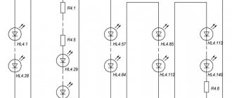
A small supply of capacitor C1 contributes to a gradual increase in power, which leads to a smooth (no more than 2 seconds) switching on of electric lamps.
Photo of a homemade temperature sensor
Temperature change indicator with thermistor and relay housing
Hello. In this article I will show how to make an electromechanical temperature change indicator. Due to its simplicity and clarity, this diagram can serve to familiarize children with the basics of electronics and attract them to the study of physics.
It is important to note that the device is precisely an indicator of temperature changes, and not a thermometer. Like any indicator, this device does not show the exact value of the measured value (in this case temperature), but only demonstrates its change. Almost all the parts for making the indicator can be obtained from old faulty instruments.
Materials and tools: - two 51 Ohm resistors; - 150 Ohm trim resistor; - thermistor; - switch; — two-pin connector (optional); — pointer milliammeter; — battery with a nominal voltage of 1.2 V, size AA or AA battery; — mounting wire with a diameter of 0.2-0.5 mm. - breadboard (optional); - soldering iron; - flux and solder;
The indicator is a Wheatstone measuring bridge. The circle with the letter A denotes an ammeter (in this case a milliammeter), it is connected directly to a measuring bridge consisting of four resistors. R1 and R3 are fixed resistors with a nominal value of 51 ohms. Resistor R2 is a variable resistance resistor and is used to configure the circuit. R meas. – a thermistor, it serves to convert temperature changes into resistance changes. The Wheatstone bridge works as follows, R1 and R2 represent one arm (branch) of the bridge, and R3 and R are measured. – second. When the resistance of both arms is equal, no current flows through the ammeter, the needle is at zero. But if the resistance of one of the arms changes, a current begins to flow through the ammeter, the value of which is higher, the greater the difference in resistance, and accordingly, the more the needle deviates. It is important that the Wheatstone bridge allows you to determine relatively small changes in the resistance value; this is of great importance for constructing an indicator, since the change in the thermistor resistance is several tens of ohms.
It is important to note that in addition to the thermistor, there is also a posistor, and although both elements are often called simply a thermistor, it should be remembered that they have opposite characteristics. The resistance of the thermistor decreases when heated, and the resistance of the posistor increases.
It is not necessary to buy a thermistor; it can be found on the board of an old faulty monitor or TV. In most cases, the part looks like the picture below, but may differ in the color of the body.
Since the part is similar in appearance to a ceramic capacitor, it is worth taking it out of the faulty device to carry out a simple check, connect a multimeter set to the resistance measurement mode to the terminals of the part, the device should show values in the range of 15 - 30 Ohms. When the body of the part heats up, the resistance should decrease.
Below I have provided a diagram according to which my sample indicator is assembled.
Then I soldered the connector for connecting the thermistor, the switch, and the battery (if using a battery, it is advisable to solder a special holder and install the battery in it). After this, I soldered a milliammeter, which was taken from an old tape recorder, but you can use any other one with a rated current of up to 200 mA.
The component leads should be carefully insulated, especially if a metal case is used to assemble the device. After that, I soldered a measuring cable consisting of a thermistor piece of two-core wire and a plug. The thermistor has no polarity, so cable assembly should not be difficult.
Then I did some preliminary setup. Its essence is as follows: after turning on the device, you need to rotate the screw of the trimming resistor to set the milliammeter needle approximately in the middle of the scale. After this, you need to heat the thermistor (for example, using a soldering iron), if the arrow deviates to the right, everything is in order, but if the arrow deviates to the left, you need to change the polarity of the milliammeter connection.
After that I moved on to making the body. Having chosen the size of the relay housing, in my case from the RS-13, I drilled holes in it for the connector and for access to the trimming resistor.
The device turned out to be quite sensitive, if you set the arrow at the border of the green part of the scale, and then hold the thermistor in your fingers, the arrow will approach the red part of the scale in a few seconds. If the thermistor is placed in snow or chilled water, the arrow opposite will move to the left.
Here are some more photos of the device:
Source
Homemade thermostat: step-by-step instructions
If you have purchased all the necessary components for assembly, all that remains is to review the detailed instructions. We will consider the example of a temperature sensor designed for 12V.
A homemade temperature controller is assembled according to the following principle:
That's all. These small steps are where all the work of creating a thermostat with your own hands lies. It may not be possible to do it yourself without certain skills right away, but with the help of photo and video instructions you will be able to test all your skills.
Thanks to its simple design, a self-created thermal controller can be used anywhere.
For example:
It is not necessary to use a digital, electronic or mechanical commercial thermal switch. Having bought an inexpensive thermal relay, adjust the power on the triac and thermocouple and your homemade device will work no worse than the purchased one.
Advantages and disadvantages
A homemade thermostat has certain advantages and disadvantages. The advantages of the device are:
- High maintainability. A thermostat made by yourself is easy to repair, since its design and operating principle are known to the smallest detail.
- The costs of creating a regulator are much lower than when purchasing a ready-made unit.
- It is possible to change the operating parameters to obtain a more suitable result.
The disadvantages include:
- The assembly of such a device is only available to people who have sufficient training and certain skills in working with electronic circuits and a soldering iron.
- The quality of operation of the device largely depends on the condition of the parts used.
- The assembled circuit requires adjustment and alignment on a control stand or using a reference sample. It is impossible to obtain a ready-made version of the device immediately.
The main problem is the need for training or, at a minimum, the participation of a specialist in the process of creating the device.
Tips and tricks
Although the device itself is quite undemanding in terms of operating conditions, the accuracy of the response depends on the quality of the primary signal, and this is especially true for automation operating in conditions of high humidity or in contact with aggressive environments. Thermal sensors in such cases should not be in direct contact with the coolant. The terminals are placed in a brass sleeve and hermetically sealed with epoxy glue. You can leave the end of the thermistor on the surface, which will contribute to greater sensitivity.
General concept of temperature controllers
Devices that record and simultaneously regulate a given temperature value are more common in production. But they also found their place in everyday life. To maintain the necessary microclimate in the house, water thermostats are often used. They make such devices with their own hands for drying vegetables or heating an incubator. Such a system can find its place anywhere.
In this video we will find out what a temperature regulator is:
In reality, most thermostats are only part of an overall circuit, which consists of the following components:
These are the three main parts of the system for maintaining specified temperature parameters. Although, in addition to them, other parts, such as an intermediate relay, may also participate in the circuit. But they perform only an additional function.
How to setup
To configure the device, you must either have a reference device or know the voltage rating corresponding to a particular temperature of the controlled environment. Individual devices have their own formulas showing the dependence of the voltage on the comparator on temperature. For example, for the LM335 sensor this formula looks like:
where T is the required temperature in Celsius.
In other schemes, adjustment is made by selecting the values of adjusting resistors when creating a certain, known temperature. In each specific case, our own methods can be used, optimally suited to the existing conditions or equipment used. The requirements for the accuracy of the device also differ from each other, so in principle there is no single adjustment technology.