Types and structure of losses
Losses mean the difference between the electricity supplied to consumers and the energy actually received by them. To normalize losses and calculate their actual value, the following classification was adopted:
- Technological factor. It directly depends on characteristic physical processes, and can change under the influence of the load component, semi-fixed costs, as well as climatic conditions.
- Costs spent on operating auxiliary equipment and providing the necessary conditions for the work of technical personnel.
- Commercial component. This category includes errors in metering devices, as well as other factors causing under-metering of electricity.
Below is an average graph of losses for a typical electric company.
Approximate loss structure
As can be seen from the graph, the highest costs are associated with transmission via overhead lines (power lines), this accounts for about 64% of the total losses. In second place is the corona effect (ionization of air near the overhead line wires and, as a consequence, the occurrence of discharge currents between them) – 17%.
Corona discharge on a power line insulator
Based on the presented graph, it can be stated that the largest percentage of non-targeted expenses falls on the technological factor.
Main causes of electricity losses
Having understood the structure, let's move on to the reasons that cause inappropriate expenditure in each of the categories listed above. Let's start with the components of the technological factor:
- Load losses occur in power lines, equipment and various elements of electrical networks. Such costs directly depend on the total load. This component includes:
- Losses in power lines are directly related to current strength. That is why, when transmitting electricity over long distances, the principle of increasing it several times is used, which contributes to a proportional reduction in current and, accordingly, costs.
- Consumption in transformers of magnetic and electrical nature ( ). As an example, below is a table that shows cost data for substation voltage transformers in 10 kV networks.
Losses in power transformers of substations
Non-target consumption in other elements is not included in this category, due to the complexity of such calculations and the insignificant amount of costs. For this, the following component is provided.
- Category of semi-fixed expenses. It includes costs associated with the normal operation of electrical equipment, these include:
- Idle operation of power plants.
- Costs in equipment providing reactive load compensation.
- Other types of costs in various devices, the characteristics of which do not depend on the load. Examples include power insulation, metering devices in 0.38 kV networks, measuring current transformers, surge limiters, etc.
- Climatic component. Inappropriate consumption of electricity may be associated with climatic conditions characteristic of the area where power lines pass. In networks of 6 kV and higher, the magnitude of the leakage current in the insulators depends on this. In main lines from 110 kV, a large share of the costs falls on corona discharges, the occurrence of which is facilitated by air humidity. In addition, during the cold season, our climate is characterized by the phenomenon of icing on the wires of high-voltage lines, as well as conventional power lines.
Ice on power lines
Taking into account the last factor, the energy costs for melting ice should be taken into account.
Topic 3.1. Power and energy losses in lines and transformers
3.1.1. General information about power and energy losses in electrical network elements
When transmitting electricity from power plants to consumers, part of the electricity is inevitably spent on heating conductors, creating electromagnetic fields and other effects. This consumption is called energy losses [5].
The word “losses” is usually associated with improper organization of the technological process, but electricity losses are caused by physical processes occurring in conductors, and it is impossible to completely get rid of them at the current stage of development of science and technology. Therefore, electricity losses are often called electricity transportation costs.
In electrical networks, power and electricity losses are determined by losses in power lines and substation transformers. In power lines, power is lost to heating the conductors, to creating electromagnetic fields, to corona, and to charging power. In transformers, power losses are divided into load losses and no-load losses. Here we are talking exclusively about so-called technical losses. The structure of electricity losses and methods for reducing them are discussed in more detail in the course “Electricity Saving”.
3.1.2. Power losses in lines
During the operation of the power supply system (PSS), power and electricity losses inevitably occur in its elements (cable and overhead power lines, transformers, electric motors, etc.) [5]. The magnitude of these losses depends on many different factors: the current passing through the element, climatic conditions, resistance (active, reactive) of the element, etc., and can reach significant sizes. Therefore, the problem of reducing power and electrical energy losses is one of the most important in the operation of solar power plants of almost any facility.
To date, several different methods are known to reduce power and electricity losses in SES elements, which are combined into two large independent groups. The first group is organizational measures, the second is technical measures.
Active power losses DP
in power lines are equal to:
DP
=3
I
2∙
R
l= , (3.1)
Reactive power and reactive energy losses are equal to:
DQ=
3
I
2 ∙
X
l = , (3.2)
where R
l,
X
l – respectively active and reactive resistance of the power line;
I
,
P
and
Q
– currents and powers flowing through the line.
From the analysis of these formulas, the following conclusions can be drawn:
— active power losses depend on both active and reactive powers transmitted along the line;
— even a slight increase in voltage leads to a significant reduction in power losses;
— reducing the line resistance leads to a reduction in power losses.
In addition, the following follows from formulas (3.1) and (3.2):
— power losses of the entire network consist of power losses in all its sections;
— with a uniformly distributed load, power losses are less than with the same load concentrated at the end of the line.
3.1.3. Energy losses in lines
One of the main indicators that determine the quality of the design and operation of electrical networks is the amount of electrical energy losses [5]. Their cost represents a significant part of the annual operating costs in the levelized costs, which serve as an economic criterion for assessing both the designed and the existing electrical network. Determination and accounting of electrical energy losses is carried out using various methods. The most widely used method is calculating the time of maximum losses, as well as the method of calculating using load graphs. In addition, in some cases, with a sufficient number of measuring instruments, it is possible to directly assess losses from the readings of electricity meters. Currently, the statistical method for calculating electricity losses based on the amount of energy passed is widely used. Since power is energy per unit time, energy loss DE is power loss multiplied by time
D
E
= DРt = 3I2 R t
. (3.3)
However, power losses in the DP
remain constant only if the current flowing through the line does not change. In reality, the current changes constantly as the operating mode of consumers changes.
If we plot the annual load graph of a distracted consumer as shown, then the annual energy losses will be proportional to the area of the quadratic load graph and can be expressed as
D
E
= I2 ( (t)R dt
.
where T is the time the consumer is turned on.
In this case, the consumer is switched on throughout the year, i.e. T
=8760 h. However, it is impossible to obtain the dependence
I
(
t
) in analytical form. Therefore, various methods are used with the introduction of “fictitious” values.
Each group of consumers (engineering consumers, textile factories, etc.) has characteristic load schedules. The loads of substations and lines are composed of consumer loads and also have characteristic graphs.
One of the frequently used methods for determining energy losses is the rms current method I
avg, i.e. such a current that, constantly flowing through the line, will give the same losses as the actual currents. Then
I
2sr kv = , (3.4)
where I
1,
I
2,... - current values at intervals
t
1,
t
2,... of the step load diagram.
Having found the value I
2sr kV, energy losses can be determined by the expression
D
E
=3I2 RT
. (3.5)
The most common method for determining energy losses is the method using the time of maximum loss.
P for some part of the time
Max.
The time during which, working with maximum load P
max, the consumer would take from the network energy equal to the energy actually received by him in a year is called
the number of hours of use of the maximum T
max. Then the energy received by the consumer will be determined by the formula
E= P
max
T
max. (3.6)
Similarly, the time during which the consumer, working with maximum losses, will cause the same losses that actually occur is called the time of maximum losses τ
. Then the energy loss in the line
DE=D P
max τ= 3
I
2max
R
lτ, (3.7)
where I
max – maximum current flowing through the line,
R
l – active resistance of the line. The number of hours of maximum use can be determined from lookup tables for the relevant consumer groups or determined from the load graph
T
max = , (3.8)
where P
1,
P
2,... - power values at intervals
t
1,
t
2,... of the step load diagram.
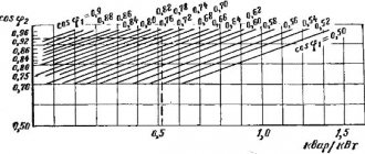
The value of τ is uniquely related to Tmax
.
It can be obtained from special curves t =¦( T
max, cosφError! The bookmark is not defined.) or from the analytical dependence:
. (3.9)
3.1.4. Power and energy losses in transformers.
A significant part of the total power and electricity losses of solar power plants are losses in transformers [5]. The power losses in them are composed of the active DP
these reactive
DQ
power.
Active power losses consist, in turn, of losses for heating the windings of the transformer DP , depending on the load current and losses for heating the steel DP
st, independent of the load current:
DP=
3
I
2
R
t
=
. (3.10)
Active resistance of the transformer windings:
R
t
=DP
to
U
2nom
/S
2nom, (3.11)
where DP
k – short circuit losses (copper losses),
S
nom – rated power of the transformer.
Reactive power losses also consist of two components: losses caused by magnetic flux leakage in the transformer and depending on the square of the load current DQ
and magnetization losses, independent of the load current
DQm=DQ
xx and determined by the no-load current
I
xx (no-load losses),
DQ
=3
I
2
X
t. (3.12)
Active losses can also be determined using another formula:
DP
t
= DP
to nom(
S
/
S
nom)2
+ DP
st, (3.13)
where S
– actual load of the transformer;
DP
knom – short-circuit losses corresponding to losses in copper at the rated load of the transformer
S
nom
.
Reactive losses can also be determined using another formula:
DQ
t= (
S
nom/100)∙(
U
k∙
K
2з+
I
xx), (3.14)
where U
k
– short circuit voltage, K
z =
S/S
nom – load factor.
Costs for supporting the operation of substations
This category includes the cost of electrical energy for the operation of auxiliary devices. Such equipment is necessary for the normal operation of the main units responsible for the conversion of electricity and its distribution. Costs are recorded using metering devices. Here is a list of the main consumers belonging to this category:
- ventilation and cooling systems for transformer equipment;
- heating and ventilation of the technological room, as well as internal lighting fixtures;
- lighting of areas adjacent to substations;
- battery charging equipment;
- operational circuits and monitoring and control systems;
- outdoor equipment heating systems, such as air circuit breaker control modules;
- various types of compressor equipment;
- auxiliary mechanisms;
- equipment for repair work, communication equipment, as well as other devices.
Electrician's Handbook. Voltage, power and energy losses
The main reason for voltage deviations in the electrical network is voltage losses in power lines and power transformers
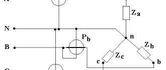
, and the voltage losses in the lines are of main importance. In Fig. 1, a shows an electrical diagram that includes a power source C and two substations connected by a line W without branches. Here U1 is the voltage at the beginning, U2 is at the end of the line.
A vector diagram of electrical quantities for line W, constructed on the basis of its equivalent circuit (Fig. 1, b), is shown in Fig. 1, c. Typically, the line load is active-inductive in nature, so the current vector İ lags in phase from the voltage vector Ú2 of the end of the line by an angle φ. The voltage vector at the beginning of line Ú1 is obtained by summing the voltage vector at the end of line Ú2 with the active ΔÚwa =İR and reactive ΔÚwp = jİX components of the voltage drop on the line İZw, where R, jX, Z are the active, inductive and impedance of the line, respectively.
The module (length) of the vector İZw is called the voltage drop on the line
. The voltage drop vector on the line can be decomposed into two components:
directed along the vector Ú2 - the longitudinal component of the voltage drop ΔÚw;
directed perpendicular to the vector Ú2 - the transverse component of the voltage drop δÚw.
Rice. 1. Line voltage loss
From point 0 in Fig. 1, with a radius equal to the length of vector 0, it is possible to draw a circular arc until it intersects at point b with the line Oα (in the direction of vector Ú2). The segment 0b is equal to the modulus of the vector Ú1, i.e., the voltage at the beginning of the line. The voltage loss in the line is equal to the length of the segment cb, i.e., the arithmetic difference U1 - U2. To simplify, the voltage loss is calculated approximately and is assumed to be equal not to the segment cb, but to the segment cd. The error resulting from such a replacement is relatively small and is acceptable in the calculations. Then we can obtain the following expression for the voltage loss in the line:
where P, Q are, respectively, active P and reactive Q load power at the end of the line; U2 is the voltage at the end of the line.
Thus, one must distinguish between voltage drop and voltage loss
on line.
Voltage drop
is the magnitude of the geometric difference between the voltage vectors at the ends of the line
|ΔÚw| = |Ú1 - Ú2|.
Voltage loss
is the arithmetic voltage difference at the ends of the line, i.e. ΔUw = U1 - U2.
Voltage loss shows how much the voltage at the end of a line differs from the voltage at the beginning. The voltage drop is usually greater than the voltage loss due to the phase shift of the vectors Ú1 and Ú2. Practice in GDS is interested in voltage loss, not voltage drop, because voltage loss is related by the simplest formula to the voltage at the beginning and end of the line.
Commercial component
These costs mean the balance between absolute (actual) and technical losses. Ideally, such a difference should tend to zero, but in practice this is not realistic. This is primarily due to the characteristics of electricity meters and electricity meters installed at end consumers. It's about error. There are a number of specific measures to reduce losses of this type.
This component also includes errors in bills issued to consumers and theft of electricity. In the first case, a similar situation may arise for the following reasons:
- the contract for the supply of electricity contains incomplete or incorrect information about the consumer;
- incorrectly indicated tariff;
- lack of control over meter data;
- errors related to previously adjusted accounts, etc.
As for theft, this problem occurs in all countries. As a rule, such illegal actions are carried out by unscrupulous household consumers. Note that sometimes incidents occur with enterprises, but such cases are quite rare, and therefore are not decisive. It is typical that the peak of thefts occurs in the cold season, and in those regions where there are problems with heat supply.
There are three methods of theft (understating meter readings):
- Mechanical . This means appropriate intervention in the operation of the device. This can be slowing down the rotation of the disk by direct mechanical action, changing the position of the electric meter by tilting it by 45° (for the same purpose). Sometimes a more barbaric method is used, namely, the seals are broken and the mechanism is unbalanced. An experienced specialist will instantly detect mechanical interference.
- Electric . This can be an illegal connection to an overhead line by “throwing”, a method of investing a phase of the load current, as well as the use of special devices for its full or partial compensation. In addition, there are options with shunting the current circuit of the meter or switching phase and zero.
- Magnetic . With this method, a neodymium magnet is brought to the body of the induction meter.
A magnet can only affect some older models of electric meters.
Almost all modern metering devices cannot be “deceived” using the methods described above. Moreover, such attempts to interfere can be recorded by the device and stored in memory, which will lead to dire consequences.
The concept of loss standard
This term means the establishment of economically sound criteria for non-target expenditure for a certain period. When standardizing, all components are taken into account. Each of them is carefully analyzed separately. As a result, calculations are made taking into account the actual (absolute) level of costs for the past period and an analysis of various opportunities that make it possible to realize the identified reserves to reduce losses. That is, the standards are not static, but are regularly revised.
The absolute level of costs in this case means the balance between the transferred electricity and technical (relative) losses. Technological loss standards are determined by appropriate calculations.
Ways to reduce losses in electrical networks
Costs can be reduced by optimizing the technical and commercial components. In the first case, the following measures should be taken:
- Optimization of the circuit and operating mode of the electrical network.
- Study of static stability and identification of powerful load nodes.
- Reduction of total power due to the reactive component. As a result, the share of active power will increase, which will have a positive impact on the fight against losses.
- Transformer load optimization.
- Equipment modernization.
- Various load balancing methods. For example, this can be done by introducing a multi-tariff payment system, in which the cost of kWh is increased during peak load hours. This will significantly reduce the consumption of electricity during certain periods of the day; as a result, the actual voltage will not “sag” below acceptable standards.
You can reduce your business costs by:
- regular search for unauthorized connections;
- creation or expansion of units exercising control;
- checking readings;
- automation of data collection and processing.
Electricity power losses in electrical networks
Chapter 5. Power and electricity
in electrical networks
5.1. Power losses in lines
Active power losses in lines are caused by active resistance of wires and cables, as well as losses due to corona in overhead lines and leakage currents through insulation in high voltage cable lines.
In a three-phase line, where the load is given in the form of total current or its active and reactive components, active power losses spent in the active resistance of the line for heating the conductors are determined by the formulas
. (5.1)
If the load is given in the form of total, active and reactive power, then the same losses can be found using the expressions
. (5.2)
As can be seen, the amount of losses depends on the transmitted power and voltage level. Increasing the voltage level allows you to reduce active power losses in line resistance. However, it should be noted that when the voltage in the networks directly supplying power consumers increases, in accordance with the static characteristics of the voltage load (see § 4.5), the power of consumers and, therefore, the power transmitted along the line may increase.
The power transmitted through the line includes active and reactive components. If the only source of active power is generators of power plants, then reactive power is generated by various devices. Moreover, some of them (compensating devices) can be installed near reactive power consumers. Let's consider the line (Fig. 5.1) along which power is transmitted. Active power losses in it
.
Let's install at the end of the line, for example, a battery of capacitors with a capacity of . In this case, the reactive power transmitted through the line will decrease to a value, which means that active power losses will also decrease
.
The reduction in active power losses will be
(5.3)
A quantitative characteristic of the effectiveness of reducing power losses from reactive power compensation is the economic equivalent of reactive power
(5.4)
It shows how much active power losses are reduced when a compensating device of value is turned on at the load node.
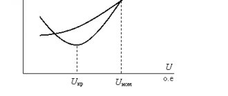
In high-voltage overhead lines, there are losses of active power to the corona, which in lines with a voltage of 330 kV and higher are determined by expression (4.10). As noted, the magnitude of specific corona losses largely depends on weather conditions and voltage.
The dependence of the average power losses to the corona on voltage has the form
, (5.5)
where U is voltage, V.
Thus, as the voltage level increases, the active power losses to the corona increase, but at the same time the active power losses in the line resistance decrease.
For high voltage cables, active power losses caused by leakage currents through the insulation can be calculated from their active conductance
. (5.6)
Along with active power losses, reactive power is also lost in power lines. These losses are caused by inductive reactances of overhead and cable lines.
If the line load is given by the current, then the reactive power losses can be found using the formula
.
For a load with a given power, the reactive power losses in the line are equal to
. (5.7)
Along with the consumption of reactive power, the line, having capacitive conductivity and corresponding charging power, is a source of reactive power. The charging power of the line, determined by formula (4.14), in some cases reduces the reactive power transmitted along the line, and therefore the loss of active and reactive power. At the same time, in light load conditions, when there is excess reactive power, charging power can cause an increase in reactive power transmitted through the line and power losses.
Methodology and example for calculating electricity losses
In practice, the following methods are used to determine losses:
- carrying out operational calculations;
- daily criterion;
- calculation of average loads;
- analysis of the greatest losses of transmitted power by day and hour;
- access to generalized data.
Full information on each of the methods presented above can be found in regulatory documents.
In conclusion, we give an example of calculating costs in a TM 630-6-0.4 power transformer. The calculation formula and its description are given below; it is suitable for most types of similar devices.
Calculation of losses in a power transformer
To understand the process, you should familiarize yourself with the main characteristics of TM 630-6-0.4.
Parameters TM 630/6/0.4
Now let's move on to the calculation.
Calculation results
Calculation of power losses in power lines
Active power losses in the power transmission line section (see Fig. 7.1) are caused by the active resistance of wires and cables, as well as the imperfection of their insulation. The power lost in the active resistances of a three-phase power line and spent on heating it is determined by the formula:
,
where are the total, active and reactive currents in the power line;
P, Q, S
– active, reactive and apparent power at the beginning or end of the power line;
U
– line voltage at the beginning or end of the line;
R
– active resistance of one phase of the power line.
Active power losses in the conductivity of power lines are caused by imperfect insulation. In overhead power lines - the appearance of corona and, to a very small extent, current leakage through the insulators. In cable power lines - the appearance of conduction current and its absorption. Losses are calculated using the formula:
,
where U
– line voltage at the beginning or end of the line;
G
– active conductivity of LEP.
When designing overhead power lines, they strive to reduce power losses to corona to zero, choosing a wire diameter such that the possibility of corona occurrence is practically absent.
Reactive power losses in the power transmission line section are caused by the inductive reactance of wires and cables. The reactive power lost in a three-phase power line is calculated similarly to the power lost in active resistances:
The charging power of the LEP generated by capacitive conductivity is calculated by the formula:
,
where U
– line voltage at the beginning or end of the line;
B
– reactive conductivity of the power line.
Charging power reduces the reactive load of the network and thereby reduces power losses in it.