Lecture No. 8
Lecture topic: “Measurement of power and resistance”
Lecture outline:
1.Power measurement in DC circuits
2. Power measurement in AC circuits
3. Direct and indirect measurement of resistance in DC circuits
4. Resistance measurement in AC circuits
1.Power measurement in DC circuits
1) indirect method:
Based on the product P = UI,
power can be determined by measuring voltage and current with a magnetoelectric ammeter and voltmeter.
Despite the simplicity of this method, it is rarely used, because two devices are required, which give an additional error
2)Direct method
– using measuring instruments – wattmeters. Electrodynamic wattmeters are the most widely used.
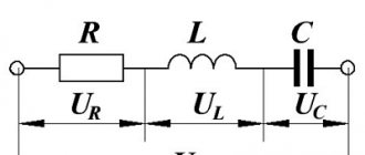
Electrodynamic wattmeter device
Design elements:
A – fixed coil (series or current coil), works like an ammeter.
It is connected in series with the energy receiver (Rн) - therefore called a series coil or current coil.
B – a moving coil with additional resistance Rd (parallel or current coil), works like a voltmeter.
Together with Rd, it is connected in parallel to the energy receiver - therefore it is called a parallel coil or voltage coil.
The angle of rotation of the moving part of the wattmeter is always proportional to the measured power: i.e. the wattmeter scale is uniform.
The direction of rotation of the wattmeter pointer depends on the relative direction of the currents in its coils. Therefore, to correctly connect the wattmeter to the measured circuit, its terminals should be distinguished:
| generator | load |
| 1. current coil terminal A (series circuit) connected to the power source. 2.Voltage coil terminal B (parallel circuit) connected to series coil. | Two others. |
Generator terminals are marked with asterisks. These clamps are called generator clamps because when they are connected to each other and to one of the generator poles, the wattmeter pointer will deviate in the desired direction.
When the wattmeter is turned on correctly, the currents in its coils are directed from the generator terminals to the load terminals.
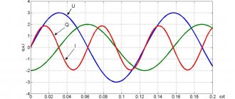
2. Power measurement in AC circuits
Single phase circuit
1.Active power
, where is the phase shift angle
between I
and
U.
In single-phase circuits, active power is measured by electrodynamic wattmeters.
They directly show the measured power taking into account the power factor - .
A reactive power
under production conditions, they are measured only in three-phase circuits.
| 2) If currents and voltages exceed the measurement limit of the wattmeter, then it is turned on through current and voltage measuring transformers. In this case, the power of the circuit is calculated as the product of the wattmeter reading and the transformation ratios of the CT and VT: . |
Three-phase circuit
In three-phase circuits active power
measured by electrodynamic and ferrodynamic wattmeters.
The number and switching circuits of wattmeters are determined depending on:
type of three-phase system (three or four wire),
its symmetry (uniform or uneven phase load)
· diagrams for connecting the phases of the energy receiver (star or triangle).
1)Three-wire system with symmetrical phase load
– single wattmeter method.
a) when connecting receivers (loads) with a star
| Conditions: The voltage system is symmetrical: . ·the load in all phases is the same: , . star connection: . |
The parallel circuit of the wattmeter is connected to phase voltage (), and through its series winding a phase current equal to linear current flows (), then the wattmeter shows power,
equal to the power of one load phase: .
Since the load is symmetrical, the total measured power is equal to triple the wattmeter reading:
Note
: — that’s why they replaced it, but .
Hence
b) when connecting the load into a triangle or when the zero point is inaccessible.
| Then the wattmeter is turned on with artificial nulldot – these are three equal resistances connected in a star, where ( - voltage coil resistance, — its additional resistance). |
1.Then the wattmeter reading Pw
equals the phase power, i.e.:
2. And the entire measured power is equal to triple the wattmeter reading:
.
Note
: when connecting the load into a triangle (replaced), and .
Then compare with a)
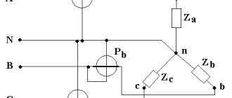
2)Three-wire system with asymmetric phase load
regardless of the connection diagram - the method of two wattmeters.
| (load connected in star) The active power of such a system is equal to the algebraic sum of the readings of two wattmeters: (linear!). |
The readings of these wattmeters are: (linear!).
? 3 phases, and 2 wattmeters. Proof:
1. The instantaneous power of a three-phase circuit can be expressed as the sum of the powers of the individual phases: . (1)
2. For the zero point of energy receivers connected by a star, according to Kirchhoff’s first law: ,
from where each of the linear currents can be expressed through the other two:
.
3.Substituting one of these expressions, for example for the current ic,
into formula (1), we get:
4. Let's move from instantaneous power to average (active): .
3)Four-wire system –
three wattmeter method.
| Then the active power will be equal to the algebraic sum of the readings of three wattmeters, each of which measures the power of one phase: . |
·You can also use one three-element wattmeter. It has three fixed coils and three movable ones, mounted on one axis.
If a wattmeter is connected to the circuit, then the torque acting on each of the moving coils will be proportional to the power of the corresponding phase. The resulting torque, equal to the sum of the individual torques, will be proportional to the active power of a four-wire three-phase current circuit. The angle of rotation of the moving part of the wattmeter will also be proportional to the same power.
Reactive power measurement in three-phase circuits
| For this purpose, single-phase (single-element wattmeters) are used. But here it is necessary to ensure phase shift between the current and voltage vectors, so that . |
This shift is obtained by turning on the wattmeter according to the following scheme ®Then the wattmeter shows the value of reactive power: |
That is, to measure reactive power, it is necessary to turn on the series circuit of the wattmeter in the same way as when measuring active power, and the parallel circuit to such a voltage to ensure a phase lag.
This condition is valid when measuring reactive power in both three-wire and four-wire systems. This circuit is called a voltage-replaced
.
Special cases
1) In a four-wire circuit -
three wattmeter method.
The reactive power of such a circuit is equal to the sum of the readings of three wattmeters of active power divided by: /See Fig. in active power/.
2) In a three-wire circuit
a) with uniform phase load
is used .
The total reactive power can be determined from the readings of two wattmeters using the formula:
,
i.e. it is determined by multiplying by the algebraic difference of the readings of two wattmeters,
where is the reading of the wattmeter included in the leading phase,
- readings of the wattmeter included in the lagging phase.
b) with uneven phase load
is used .
The total reactive power is determined by the formula: /See Fig./
3. Direct and indirect measurement of resistance in DC circuits
Direct resistance measurement
For this purpose special devices are used:
OhmmetersMeasure average resistances | MegaohmmetersMeasures large resistances (insulation resistance) |
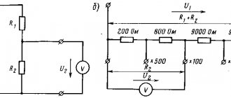
Ohmmeters
Let's consider the device of an ohmmeter with serial connection
| The ohmmeter reading is affected by the voltage of the power source (battery) - it changes frequently. Therefore, before starting the measurement, it is necessary to calibrate the device - set the constant current ® |
The instrument pointer is set to the zero scale division using an adjusting resistor when closed
key
Kl
(then no current flows through - along the path of least resistance).
When the key is open
current flows through the device: , where is the adjusting resistor.
At constant values of U
, and the angle of rotation of the moving part depends only on the resistance, the values of which are plotted on the scale.
Special cases:
1) if (min), then I
and
(since ) — max.
2) if (max), then I
u = 0 (min)
Therefore, the scale looks like: . That is, such an ohmmeter is best used for measuring average resistances - up to several kOhms. (at low values it has low sensitivity).
And for ohmmeters with parallel connection
normal scale - . Used to measure small resistances.
Megaohmmeters
Disadvantage of ohmmeters:
Readings depend on battery voltage and require constant calibration.
Therefore, ratiometric measuring mechanisms are used in ohmmeters. Such devices are called megohmmeters
. In this case, a DC network or a special built-in generator is used for power supply.
| There are 2 moving coils with resistances and . included in series with . The currents flowing through the frames are equal: , . |
The angle of deviation of the ratiometer is determined by the ratio of the current within its framework (see the equation of the ratiometer scale): .
Since R 1,
R 2 and R d are
constant values for each ratiometer, the angle of deviation depends only on the measured resistance.
Modern megohmmeters are manufactured for voltages of 100, 250, 500, 1000 and 2500 V.
Indirect resistance measurement
Indirect method | ||
| ammeter method and voltmeter | compensation method (on potentiometer) | comparison method (pavement) |
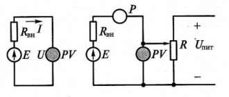
Ammeter and voltmeter method
For
: average resistance measurements.
The basis of the method
- measuring current and voltage in the circuit with the desired resistor and determining its resistance according to Ohm’s law: .
Two circuits for connecting an ammeter and a voltmeter are used.
1)
In the first circuit, since the ammeter and the measured resistance are connected in series, then
That is, the voltmeter readings are equal to the sum of the voltages on the ammeter and on the resistance.
Types of devices for taking measurements
Almost all multifunctional measuring instruments have the ability to measure the impedance value. Based on their operating principle and functionality, manufactured devices can be digital or analog. At the same time, their important characteristics are the error and measurement range.
Before you start working with the tester, you need to make sure that its batteries are in good condition. If a digital type of device displays a blinking battery indicator, this means that the battery needs to be replaced. For a pointer instrument, a signal to replace the power elements will be the inability to set the pointer to the zero position.
To obtain the correct result, it is necessary not only to use the configured device, but also to monitor the ambient temperature. As is known from the laws of physics, when heated, the resistance value of conductors increases, and that of semiconductors decreases. The optimal temperature is considered to be 20 degrees Celsius.
Digital multimeter
The main feature of a digital multimeter is the presence of a screen; the measured value is clearly displayed on it. The operating principle of the device is based on comparing the measured signal with a reference signal; for this, an analog-to-digital converter is used.
To carry out a measurement, the tester is connected with a set of wires to the element being measured. At one end of each wire there is a plug intended for installation in the meter socket, and at the other there is a contact probe. The procedure for measuring the resistance of a resistor with an electronic multimeter can be represented as the following:
- Pressing the ON/OFF button turns on the device.
- The probes are connected to the two ends of the resistor, the reverse ends of the wires to the Ω and COM connectors.
- The switch sets the approximate resistance.
- If a unit is displayed on the indicator, the switch should be moved up one position, i.e., increase the measurement limit.
- If, when taking readings, numbers other than one are displayed on the screen, this will be the resistance value.
In the same way, you can measure the resistance of the pn junction of a semiconductor. A digital device is convenient to measure constant resistance, but it is useless when you need to find out its variable value. For such measurements, it is preferable to use a pointer instrument.
Pointer device
The very first measuring instruments were equipped with a pointer device. This device was an electromechanical head. Structurally, it is made in the form of a frame located in a magnetic field. An electrical signal is supplied to this head through various resistances. Depending on the current strength, the arrow in the frame deviates, settling in a certain position. The range of the needle deflection is calibrated, according to these values and the required value is calculated.
The technical capabilities of an analog tester are largely determined by the sensitivity of the magnetoelectric measuring device. Its main advantage is its inertia and immunity to interference during the measurement of DC voltage and resistance value.
Pointer instruments are ideal for displaying signal dynamics. The tester instantly shows its change. At the same time, such a device has a large error when measuring in high-resistance circuits, and there is some difficulty in interpreting the measurement results.
The device is turned on according to the instructions indicated on the back of the battery cover. The switch button selects the operating mode for a constant, variable value or resistance (respectively “—”, “~”, “Ω”). A double click is used for a measurement pair. The calculation range switch is set to a fixed value corresponding to the expected measurement value.
Before measuring the resistance value, the tester is adjusted by rotating the zero knob until the arrow points to the “∞” value. When choosing the “Ω” measurement range, the resistance values are not marked with the maximum numbers in this range, but have the following form: x1, x10, x100. This means that the resulting value will be measured in Ohms, kOhms, and MOhms. Active resistance is measured from a direct current source (battery) installed in the device.
Having turned on and prepared the tester, you need to attach the probes to the object being tested. According to the arrow readings, the result will appear on the measuring scale, which is then multiplied by the range multiplier.
Using a Megger
A megohmmeter is a specialized measuring device. Before starting measurements, you must strictly adhere to the requirements of the PUE (electrical installation rules). The basic rules include:
- Measurements are taken at the limit of the tester, which exceeds the highest possible resistance value. If such a value is unknown, then they start with the maximum possible limit, which is reduced to the minimum possible to improve the accuracy of the result.
- Before checking the resistance with a tester, you will need to make sure that the object being tested is de-energized.
- All elements with reduced insulation, capacitors, semiconductors are short-circuited before testing begins.
- During the measurements, the test object is grounded.
- After completing measurements, especially for devices with large capacitance (for example, long-distance wires), before disconnecting the probes of the device, it is necessary to remove the residual charge by shorting it to ground.
- Taking readings of the insulation resistance of power and lighting wiring occurs with switches turned off, fuses removed, and lamps removed.
- It is strictly prohibited to measure insulation near high voltage lines or during a thunderstorm.
A megohmmeter is a complex device consisting of a current generator and a measuring head. Also included are: current-limiting resistors, terminal blocks, a dielectric housing and a mode switch.
The device has three terminals for external connection of wires. The ground is connected to one, the line to the other, and the screen to the third. Which wire is connected where is indicated in the instructions for the device.
The ground and line terminals are used for any insulation readings relative to the ground loop, and the shield contact is needed to reduce the influence of leakage currents. Such currents appear when measuring between two wire strands located parallel to each other. The screen contact is connected with a special wire that comes with the device.
We recommend reading: How to make a tube headphone amplifier with your own hands
After connecting all the probes on old-style devices, you will need to twist the knob, which will ensure the operation of the internal generator and the supply of voltage to the object being tested. In modern devices, a button is used instead of a handle, and power is taken from installed batteries or galvanic batteries. The generator voltage can range from 100 volts to 2.5 kV. As soon as the voltage is applied, for a pointer instrument, readings are taken from the arrow on the scale corresponding to the selected range, and for a digital type of instrument, readings are taken in the form of numbers on the indicator.
Then the measured resistance is:
, i.e.
A measurement error appears equal to .
Therefore, this circuit is used for measuring resistances that are larger than the resistance of the ammeter (100 times or more):
If , then â — it can be neglected, and .
2)
In the second circuit, since the voltmeter and the measured resistance are connected in parallel, then
That is, the ammeter readings are equal to the sum of the currents through the voltmeter and resistance.
Diode resistance measurement
Diodes are a nonlinear element whose characteristics are directly dependent on the voltage that is applied to it. Under the influence of voltages and operating currents, the parameters of the diodes can change significantly. In addition, their resistance values may vary when measured with different multimeters. This occurs due to the appearance of auxiliary voltage on the probes, which is not the same for different testers.
Recommended reading: Stepper motor control
For this reason, it is necessary to know the technical data of the multimeter with which measurements are taken. Only after this will it be possible to compile the current-voltage characteristic of the diode. But it often happens that in the accompanying documents for the tester, the values characterizing the auxiliary voltage on the probes are not indicated. Therefore, a test measurement is required.
To do this, take a capacitor with an average capacity, charged with auxiliary voltage. On the multimeter, the regulator is set to the resistance measurement position. The red probe is applied to the positive terminal of the capacitor, the black one to the negative terminal. The result of the measurements, after the readings on the display have stabilized, will be the R data, then inserted into the formula:
Substituting the resistance value in place of “R”, the current strength “I” is found. Next, observing the current-voltage characteristic, the coincidence of the resulting point with the position of the intersection of I and U is analyzed. In case of minor deviations, there can be only one conclusion - the diode is in working condition. Even if the deviations are relatively large, but at the same time the diode “opens” and “closes,” it can be used, but only in circuits where a low accuracy value is allowed.
reference Information
Documents • Laws • Notices • Document approvals • Contracts • Requests for proposals • Technical specifications • Development plans • Document management • Analytics • Events • Competitions • Results • City administrations • Orders • Contracts • Work execution • Protocols for consideration of applications • Auctions • Projects • Protocols • Budgetary organizations Municipalities • Districts • Education • Programs Reports
: • by references • Documentary base • Securities
Regulations
: • Financial documents
Resolutions
: • Categories by topic • Finance • cities of the Russian Federation • regions • by exact dates Regulations
Terms
: • Scientific terminology • Financial • Economic
Time
: • Dates • 2015 • 2016 Documents in the financial sector • in the investment sector • Financial documents - programs
Types of multimeters
First of all, let me remind you of Ohm's law. To find resistance (R), you need to know the voltage (U) in the conductor and the current (I) passing through it. When these quantities are known, all that remains is to use the formula: R = U / I. And the simplest ohmmeter was an ammeter into which a current source was mounted. Only the measuring scale was marked in Ohms.
The ancient device performed only one function - measured resistance. But he did it accurately and quickly. Now the ohmmeter acts as a component of one modern measuring device called a multimeter. This digital instrument can perform a range of electrical measurements in various directions.
But analog mechanisms have not gone out of use. As a rule, they perform only three functions - they measure voltage, current and resistance. That's why they are called ampere-voltmeters. And in common parlance - avometers. Among older professional electricians, another name has been assigned to such a device - tester.
Source avito.st
Analog avometers are hopelessly outdated and also have a lot of serious shortcomings. One of them is the absence of an alarm when the battery is low. If the battery is low, the device begins to provide incorrect information and this is not immediately recognized. But a digital multimeter, with insufficient current, simply refuses to work immediately. And at the same time it signals a low battery with a light.
A modern multimeter has an electronic display on which all information is displayed. As well as a switch for measuring ranges, each of which can be precisely adjusted. And measuring resistance with a multimeter is not difficult even for a beginner. You just need to select the desired mode.
Education and science
Science
: Tests • Scientific and technological progress • Pedagogy • Work programs • Faculties • Methodological recommendations • School • Vocational education • Student motivation
Subjects
: Biology • Geography • Geology • History • Literature • Literary genres • Literary characters • Mathematics • Medicine • Music • Law • Housing Law • Land Law • Criminal Law • Codes • Psychology (Logic) • Russian Language • Sociology • Physics • Philology • Philosophy • Chemistry • Jurisprudence
In what units is resistance measured?
Electrical resistance is the resistance offered by a conductor to an electric current passing through it. The main unit of measurement in the SI system will be ohm; in the GHS system there is no special indicator. Resistance (often symbolized by the letter R) is considered, within certain limits, to be constant for a particular conductor.
- R - resistance;
- U is the difference in electrical potential at the ends of the conductor in volts;
- I - the current that flows between the ends of the conductor under the influence of a potential difference, measured in amperes.
Resistance measurement
Business and finance
Business
: • Banks • Wealth and prosperity • Corruption • (Crime) • Marketing • Management • Investments • Securities: • Management • Open Joint Stock Companies • Projects • Documents • Securities - control • Securities - valuations • Bonds • Debts • Currency • Real estate • (Rent) • Professions • Work • Trade • Services • Finance • Insurance • Budget • Financial services • Loans • Companies • State enterprises • Economics • Macroeconomics • Microeconomics • Taxes • Audit Industry
:
• Metallurgy • Oil • Agriculture • Energy
Construction
• Architecture • Interior • Floors and ceilings • Construction process • Building materials • Thermal insulation • Exterior • Organization and production management
Photo blogs
Art
• Children's creativity • Paintings • Art • Congratulations • Film review • Musical world • Russian rock
World
• People of the world • The world around us • My homeland is the USSR • Nature Channel • Stones and minerals • Cooking, food • Construction and architecture • Under construction • Transport • Weapons • Military transport
beauty
• Fashion Pandia.ru • Girls and Girls
School
• Tests for the Unified State Exam • Solver books • Unified State Examination • 10th and 11th grades • Various textbooks • 4th grade • Russian language grades 5-9 • 5th grade • 6th grade • 7th grade • 8th grade
Wisdom
• Cliparts • Quotes
Author Directory (private accounts)
AutoAuto service • Auto parts • Products for auto • Auto repair centers • Auto accessories • auto parts for foreign cars • Body repair • Auto repair and maintenance • Car chassis repair • Auto chemicals • oils • technical centers • Gasoline engine repair • auto electrical repair • Automatic transmission repair • Tire fitting BusinessAutomation of business processes • Online stores • Construction • Telephone communications • Wholesale companies LeisureLeisure • Entertainment • Creativity • Catering • Restaurants • Bars • Cafes • Coffee shops • Night clubs • Literature TechnologiesAutomation of production processes • Internet • Internet providers • Communications • Information technologies • IT companies • WEB studios • Website promotion • Software sales • Switching equipment • IP telephony | InfrastructureCity • Authority • District administrations • Courts • Utilities • Teen clubs • Public organizations • City information sites The sciencePedagogy • Education • Schools • Training • Teachers GoodsTrading companies • Trade and service companies • Mobile phones • Accessories for mobile phones • Navigation equipment |
Measuring the resistance value using the direct assessment method
This measurement technique involves using an ohmmeter to take readings of the parameters of the electrical system and determine its resistance level. This measurement option is allowed only in situations where the customer can tolerate the possibility of obtaining not entirely accurate results.
Due to insufficient accuracy, the ohmmeter measurement method is used to determine approximate resistance values, as well as in cases when checking switching networks is required. To measure resistance, you should use ohmmeters with a resistance measurement range from 0.1 Ohm to 1000 kOhm.
As the main ohmmeter for measuring low resistances, ratiometric devices of the M246 type are usually used, equipped with an optical pointer and tentacles that can be cleaned independently.
It is also worth noting that in some cases, instruments called contact meters can be used to measure small resistance values. This is high-quality equipment that can determine resistance with an error of no more than one and a half percent.
The main measuring devices for checking the resistance on transformer windings are modern potentiometers, which are highly accurate. They work using the method of compensatory resistance measurement.
Single bridges are used when it is necessary to measure the resistance level, the nominal value of which ranges from 1 Ohm to 1 MOhm. Such a bridge can produce results with noticeable errors, in some cases reaching 15%.
Example of a technical report
Back
Forward
Below you can use the online calculator to calculate the cost of electrical laboratory services.
Bridge method
Devices used to implement such measurements are called measuring bridges. A four-arm or single bridge contains two diagonals and four arms:
The bridge is formed by three resistors, the values of which are known - R2, R3, R4 and, accordingly, the resistance, the value of which must be measured Rx. It is necessary to connect a power source to one of the diagonals of the bridge, for this case the source E is connected to terminals a and b, and the other is a zero indicator NI (terminals c and d), which acts as an indicator of the symmetry of the bridge. When the potentials at points c and d are equal, then the deviation in the NI flows current INI = 0 and its deviation is also zero. The bridge is in a state of balance. The following relationships will be satisfied: I1 = I2, I3 = I4, RxI1=R3I3, R2I2=R4I4. Taking into account the equality of currents and dividing the last two equations term by term, we obtain:
From this expression we can isolate the required resistance:
The R2 arm is called the comparison arm, and the relation arms R3 and R4, respectively.
The single bridge method measures only average resistances. It is not recommended to measure small and large resistances with them. The lower measurement limit of the bridge (units of Ohm) is limited by the influence of the resistance of the wires and contacts that are connected to the AC arm in series with the Rx measurement object. The upper limit (105 Ohm) is limited by the shunting effect of leakage currents.