Insulation resistance measurement
The resistance of the main insulation of current transformers, the insulation of the measuring capacitor and the terminal of the last lining of the paper-oil insulation of the capacitor type is measured with a 2500 V megohmmeter. The
resistance of the secondary windings and intermediate windings of cascade current transformers relative to the base is measured with a 1000 V megohmmeter.
During operation, measurements are made:
- on current transformers 3-35 kV - during repair work in the cells (connections) where they are installed;
- on 110 kV current transformers with paper-oil insulation (without equalizing plates) - in case of unsatisfactory oil test results in accordance with the requirements of Table. 25.4, paragraphs. 1-3 (area of “risk”);
- on current transformers 220 kV and above with paper-oil insulation (without equalizing plates) - in the absence of insulation control under operating voltage and unsatisfactory oil test results in accordance with the requirements of Table. 25.4, paragraphs. 1-3 (area of “risk”);
- on current transformers with paper-oil insulation of capacitor type 330 kV and above - in the absence of insulation control under operating voltage - once a year. The measured insulation resistance values must be no less than those given in table. 1.
Table 1
| Voltage class, kV | Permissible insulation resistance, MOhm, not less | ||||
| Basic insulation | Test lead | Outer layers | Secondary windings* | Intermediate windings | |
| 3-35 | 1000/500 | — | — | 50 (1)/50 (1) | — |
| 110-220 | 3000/1000 | — | — | 50 (1)/50 (1) | — |
| 330-750 | 5000/3000 | 3000/1000 | 1000/500 | 50 (1)/50 (1) | 1/1 |
*The insulation resistances of the secondary windings are given: without brackets - with the secondary circuits disconnected, in brackets - with the secondary circuits connected.
Note: The numerator indicates the insulation resistance values of current transformers during commissioning, and the denominator indicates during operation.
For cascade current transformers, the insulation resistance is measured for the current transformer as a whole. If the results of such measurements are unsatisfactory, the insulation resistance is additionally measured in stages.
Testing of current and voltage instrument transformers
Before starting the tests, a visual inspection is carried out, checking the technical data sheet, the condition of the porcelain insulators, the number and location of the ground connections of the secondary windings. The secondary grounding test is carried out where it can be safely disconnected without removing the high voltage, at the protection panel.
The threads in the lamellas of the current transformer terminals are also checked. Transformers of current classes D and Z are checked for completeness; the kit number must match.
Built-in transformers are checked for dryness and installed in accordance with the inscriptions “top”/”bottom”. For switches with built-in current transformers, check the presence of seals in pipes and prefabricated boxes through which the current transformer circuits pass.
When inspecting oil transformers, remove the rubber washer from under the filler plug.
Checking the insulation resistance of windings
Using a megohmmeter for a voltage of 1-2.5 kV, check the resistance of the primary insulation, each of the secondary windings and the resistance between the windings.
The insulation strength of the windings is tested with a voltage of 2 kV for one minute.
The insulation of secondary windings is allowed to be tested simultaneously with secondary switching circuits with an alternating current voltage of 1 kV for 1 minute.
All tests are carried out in accordance with regulations.
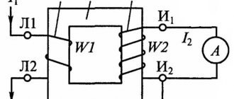
Checking the polarity of the secondary windings of current transformers
This test is carried out using the direct current pulse method using a galvanometer.
By closing the circuit, they control the direction of deflection of the device arrow; when deflecting to the right, the unipolar clamps are those that are connected to the “pluses” of the battery and the device. For testing, batteries or dry batteries are used as a current source.
Checking the transformation ratio of current transformers
The load transformer NT supplies the primary winding with a current close to the rated one, at least 20% of the rated one. The transformation ratio is checked on all branches for all secondary windings.
If there is no marking on the built-in transformers, it is restored as follows:
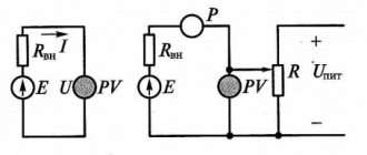
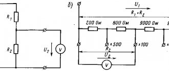
The voltage X of the AT autotransformer or potentiometer is applied to two randomly selected branches of the current transformer. A voltmeter V measures the voltage between all branches. The maximum voltage value will be at the extreme terminals A and D, between which the full number of turns of the secondary winding of the current transformer is contained. At the beginning and end of the winding determined in this way, a voltage is supplied from the autotransformer at the rate of 1 V per turn (the number of turns is determined according to the catalog data). After this, measuring the voltage across all branches, which will be proportional to the number of turns, their marking is determined.
Removal of magnetization characteristics of current transformers
A turn short circuit in the secondary winding is the most common defect in transformers. It is detected during testing of magnetization characteristics, which are fundamental in assessing faults and determining errors. A defect is detected by a decrease in magnetization and a decrease in steepness.
When even a few turns are short-circuited, the performance drops sharply.
The obtained characteristics are evaluated by comparison with typical values, or with data obtained by testing other transformers of the same type with the same coefficients and accuracy class.
It is not recommended to measure the characteristics with a rheostat, due to the possibility of residual magnetization of the steel core of the current transformer when the current is turned off.
It is necessary to record in the inspection protocol which scheme the inspection was carried out, so that the obtained values can be used for subsequent inspections.
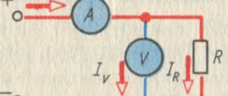
For transformers of a high accuracy class and with a high transformation ratio, it is enough to take the characteristic up to 220 V. When taking the magnetization characteristics, the voltmeter is included in the circuit before the ammeter so that the current passing through it is not included in the value of the magnetizing current. The ammeter and voltmeter used in measurements must be of an electromagnetic or electrodynamic system.
It is not recommended to use detector, electronic and other devices that respond to the average or amplitude value of the measured quantities in order to avoid possible distortions of the characteristics.
Checking voltage transformers
Testing voltage transformers is no different from testing power transformers. The methods for checking the additional winding of 5-leg voltage transformers of the NTMI type differ, since the winding is connected in an open triangle.
The polarity is checked by alternately connecting the “plus” of the battery to all winding terminals, and the “minus” remains zero. If the connection is correct, observe the deviation of the galvanometer needles in one direction.
After connecting the transformer to the network, it is necessary to measure the unbalance voltage.
Measurement of tgδ insulation
Measurements of tgδ for current transformers with main paper-oil insulation are carried out at a voltage of 10 kV. During operation, measurements are made:
- on current transformers with voltage up to 35 kV inclusive - during repair work in the cells (connections) where they are installed;
- on 110 kV current transformers with paper-oil insulation (without equalizing plates) - in case of unsatisfactory oil test results according to the requirements of Table. 25.4, paragraphs. 1-3 (area of “risk”);
- on current transformers 220 kV and higher with paper-oil insulation (without equalizing plates) - in the absence of control under operating voltage and unsatisfactory results of oil tests according to the requirements of Table. 25.4, paragraphs. 1-3 (area of “risk”);
- for current transformers with paper-oil insulation of capacitor type 330 kV and above - in the absence of control over the operating voltage - once a year.
The measured values, normalized to a temperature of 20°C, should be no more than those indicated in the table. 2. For cascade current transformers, tgδ of the main insulation is measured for the current transformer as a whole. If the results of such measurements are unsatisfactory, tgδ of the main insulation is additionally measured in stages.
table 2
| Insulation type | Limit values tgδ, %, of the main insulation of current transformers at rated voltage, kV, normalized to a temperature of 20°C | ||||||
| 3-15 | 20-35 | 110 | 220 | 330 | 500 | 750 | |
| Paper-bakelite | 3,0/12,0 | 2,5/8,0 | 2,0/5,0 | — | — | — | — |
| Basic paper-oil and capacitor insulation | — | 2,5/4,5 | 2,0/3,0 | 1,0/1,5 | No more than 150% of what was measured at the factory, but not higher than 0.8. No more than 150% of what was measured during commissioning, but not higher than 1.0. | ||
Note. The numerator indicates the tgδ values of the main insulation of current transformers during commissioning, and the denominator - during operation.
Why is the polarity of the current transformer windings checked?
Despite the fact that on industrial CT designs the polarity of the secondary coil is indicated on the product itself, the following unforeseen situations are possible:
- These designations are missing for some reason (erased, for example).
- The markings on the TT body and on the coil built into it do not match.
If the order of switching on the secondary (step-down) coil is confused, an alternating signal shifted by 180 degrees will be induced in it. In this case, the electric meter connected to it will begin to take into account the reactive load, and its readings will be underestimated. Any representative of energy networks in this situation has the right to apply penalties to the violator.
High voltage test
3.1 P. High voltage test of main insulation
The test voltage values of the main insulation are given in table. 3. Test duration for current transformers with porcelain external insulation is 1 min, with organic insulation – 5 min. It is allowed to test current transformers together with the busbar. Current transformers with voltages over 35 kV are not subject to increased voltage tests.
Table 3
| Voltage class of electrical equipment, kV | Test voltage, kV | |||||
| Power transformers, shunt and arc suppression reactors | Devices, current and voltage transformers, current-limiting reactors, insulators, bushings, coupling capacitors, shielded conductors, busbars, switchgear and package transformer substations | |||||
| At the factory | During commissioning | In use | At the factory | Before commissioning and in operation | ||
| Porcelain insulation | Other types of insulation | |||||
| Up to 0.69 | 5,0/3,0 | 4,5/2,7 | 4,3/2,6 | 2,0 | 1 | 1 |
| 3 | 18,0/10,0 | 16,2/9,0 | 15,3/8,5 | 24,0 | 24,0 | 21,6 |
| 6 | 25,0/16,0 | 22,5/14,4 | 21,3/13,6 | 32,0 (37,0) | 32,0 (37,0) | 28,8 (33,3) |
| 10 | 35,0/24,0 | 31,5/21,6 | 29,8/20,4 | 42,0 (48,0) | 42,0 (48,0) | 37,8 (43,2) |
| 15 | 45,0/37,0 | 40,5/33,3 | 38,3/31,5 | 55,0 (63,0) | 55,0 (63,0) | 49,5 (56,7) |
| 20 | 55,0/50,0 | 49,5/45,0 | 46,8/42,5 | 65,0 (75,0) | 65,0 (75,0) | 58,5 (67,5) |
| 35 | 85,0 | 76,5 | 72,3 | 95,0 (120,0) | 95,0 (120,0) | 85,5 (108,0) |
3.2. High voltage test of insulation of secondary windings
The test voltage for insulating the secondary windings together with the circuits connected to them is assumed to be 1 kV. The duration of test voltage application is 1 min.
Safety precautions
When carrying out measurements with special instruments, the following precautions must be observed:
- Persons who have mastered the rules of working with measuring equipment are allowed to work.
- They must undergo mandatory training regarding safe techniques for working with CTs.
- When determining the polarity of the secondary winding, the meter is connected to its terminals until the pulse is applied to the primary circuit.
Only if you follow these rules can you protect yourself from potential threats.
Removing magnetization characteristics
The characteristic is removed by increasing the voltage on one of the secondary windings until saturation begins, but not higher than 1800 V. If the windings have branches, the characteristic is removed on the working branch. During operation, only three control points can be removed. The taken characteristic is compared with the typical magnetization characteristic or with the magnetization characteristics of serviceable current transformers of the same type as those being tested. Differences from the values measured at the manufacturer or from those measured on a working current transformer of the same type as the one being tested should not exceed 10%.
Literature
- PUE 7. Rules for electrical installations. Edition 7.
- Rules for technical operation of consumer electrical installations.
- STO 34.01-23.1-001-2017. “Scope and standards of testing. Electrical equipment.
- GOST-7746-2001 “Current transformers. General technical conditions".
- GOST IEC 60044-1-2013 Instrument transformers. Part 1.
- GOST R IEC 61869-2-2015 Instrument transformers. Part 2.
- RD 34.45-51.300-97 “Scope and standards for testing electrical equipment.”
- RD 153-34.0-35.301-2002 “Instructions for testing current transformers used in relay protection and measurement circuits.”
- C57.13-2016 - IEEE Standard Requirements for Instrument Transformers.
Plekhanov A.V. NPP "Dynamics" Cheboksary July 2021
Transformer oil testing
When commissioning current transformers, fresh dry transformer oil before and after filling (topping up) into transformers must be tested in accordance with the requirements of Section 25. During operation, transformer oil from current transformers with voltages up to 35 kV inclusive may not be tested. Oil from current transformers 110-220 and 330-500 kV, not equipped with an operating voltage control system, is tested in accordance with the requirements of paragraphs. 1-3 tables 25.4 taking into account section. 25.3.2 – once every 2 years (for sealed current transformers – according to the manufacturer’s instructions). Oil from current transformers equipped with a control system under operating voltage, when the controlled parameters reach the limit values given in table. 4, tested according to the requirements of table. 25.4 (clauses 1-7).
Table 4
| Voltage class, kV | Limit values, %, of parameters δtgδ and δY/Y | |
| with periodic monitoring | with continuous monitoring | |
| 220 | 2,0 | 3,0 |
| 330-500 | 1,5 | 2,0 |
| 750 | 1,0 | 1,5 |
For oil-filled cascade current transformers, the condition of the transformer oil in each stage is assessed according to standards corresponding to the operating voltage of the stage.
external inspection
During an external inspection of instrument transformers, they check the presence of a passport, the condition of the porcelain insulators, as well as the number and location of the grounding connections of the secondary windings. Grounding of the secondary windings of instrument transformers must be carried out in one place - on the protection panel or on the terminal assembly, i.e., where the ground can be safely disconnected without removing the high voltage. In addition, check the serviceability of the threads in the lamellas of the current transformer clamps. For current transformers of classes D and 3, intended for operation in differential and ground protection circuits, their completeness is also checked. All transformers in a given kit must have the same kit number. Built-in current transformers must be dried before installation, and during installation it is necessary to ensure that they are installed in accordance with the factory inscriptions “top” and “bottom”. For switches with built-in current transformers, check the presence of seals in pipes and prefabricated boxes through which the current transformer circuits pass. When inspecting voltage measuring transformers, you must ensure that the feed-through pins do not rotate. Before putting into operation voltage transformers filled with oil, it is necessary to remove the rubber washer from under the oil filling plug.