Content
- 1. General part
- 2. Determination of the load on current transformers for measuring instruments
- 3. Determination of the voltage on the secondary winding of the current transformer
- 4. Determination of the load on current transformers for relay protection
- 5. Determination of the calculated multiplicity (Col.) for selecting the permissible load (Zadd.) on current transformers according to the maximum multiplicity curves
- 5.1 Current protection with independent characteristic
- 5.2 Current cut-offs
- 5.3 Overcurrent protection with dependent characteristic
- 5.4 Directional current and distance protection
- 5.5 Differential current protection
- 5.6 Differential-phase high-frequency protection
- 5.7 Longitudinal differential current protection of lines
- 6 Determination of design load Zн
- 7. Determination of the resistance of connecting wires
- 8. Reference data on the consumption of relay equipment
a common part
Good day to all! I present to your attention the standard work “Instructions for calculating current transformer loads” No. 48082-e “Teploelektroproekt”.
The secondary load on current transformers (CTs) consists of:
- a) wire resistance - rpr;
- b) impedance of relays and measuring instruments - Zр and Zп;
- c) transition resistance taken equal to - rper = 0.05 Ohm.
According to GOST, current transformers must comply with one of the following accuracy classes: 0.5; 1; 3; 5P; 10R.
Accuracy class 0.5 must be ensured when powered from the current transformer of the metering meters. When powering panel measuring instruments, the accuracy class of current transformers must be at least 3. If it is necessary for measurements to have a higher accuracy class, current transformers must be selected according to an accuracy class one step higher than the corresponding measuring device.
For example: for class 1 devices, current transformers must provide class 0.5; for devices - 1.5 current transformers must provide accuracy class 1.0.
Requirements for current transformers for relay protection are discussed below.
When calculating the load on a CT, for the purpose of simplification, it is allowed to add the resistances of the elements of the secondary circuit of the CT arithmetically, which creates a certain design margin.
The current consumption of relay and measuring equipment windings is given in section “7. Reference data on the consumption of relay equipment." For convenience and simplification of calculations in these applications, consumption is given in Ohms. For those devices and relays for which the catalogs indicate their consumption in VA, the resistance in Ohms is determined by the expression
where: S – power consumption in current circuits, VA; I – current at which the power consumption is specified, A.
When calculating the resistance of wires (cables) in the secondary circuits of CTs, the following is used:
Where:
- rpr - active resistance of wires (cable cores) from the current transformer to the device or relay, Ohm;
- l – length of the wire (cable) from the current transformer to the installation site of measuring instruments or relay equipment, m;
- S – cross-section of wire or cable core, mm2;
- γ – specific conductivity, m/Ohm.mm2 (for copper γ = 57, for aluminum γ = 34.5).
Determination of the actual coefficient of the maximum multiplicity Kpk.fact
So, to determine the actual limiting multiplicity coefficient Kpk.fact, the following initial data are required:
a) TT passport data, namely
- Snom — rated secondary load of the current transformer, VA;
- Ztr is the internal resistance of the current transformer, Ohm;
- Kpk.nom – nominal limiting factor;
- Ifirst is the primary rated current of the current transformer, A;
- Isecond is the secondary rated current of the current transformer, A.
b) The connection diagram of the current transformers and secondary load must be known
c) It is necessary to know which devices are connected to the secondary winding of the CT, as well as with which wires this connection is made.
Now it is necessary to determine the value of the secondary load connected to the CT circuits. To do this, we will use ready-made formulas borrowed from the book of Shabad M.A.
Table 1 – Calculation formulas for determining the secondary load of current transformers Zn.calc.
It is clear that in the formulas Zn.calc is the calculated value of the secondary load connected to the CT circuits; rpr – resistance of the wires connecting the current transformer and the protection relay; rper – transition resistance. Taken equal to 0.1 Ohm; Zr, Zr.f, Zr.rev – relay resistance.
Since microprocessor-based protection relays are now mainly used, their power consumption through current circuits is very small. Therefore, in the formulas, instead of Zр, Zр.ф, Zр.орр we substitute the value of power consumption for the current circuits of the microprocessor relay (in Ohms). If in each phase and in the neutral return wire its own separate relay is installed, then the value of the power consumption of each relay must be substituted into the formulas.
If in the information on the relay the power consumed by current circuits is given in W or VA, conversion to Ohms is carried out using the formula
Zр(Ohm) = Sp(W) / I 2first
Similarly, the rated power of a current transformer is converted from VA to Ohms
Znom.tt (Ohm) = Snom.tt (VA) / I 2first
Wire resistance rpr is calculated using the formula
rpr = Lpr / (γpr · Spr), Ohm
where: Lpr – length of wires from the CT terminals to the relay, m Spr – wire cross-section, mm2; γpr – specific electrical resistance, depending on the wire material
- γpr = 57 m/Ohm mm2 – for copper
- γpr = 34.5 m/Ohm mm2 – for aluminum
Now it is necessary to determine the actual limiting factor using the formula
Load determination on current transformers for measuring instruments
The load on the CT for measuring instruments consists of the resistances of the measuring equipment connected in series, connecting wires and transition resistances in contact connections.
The magnitude of the design load Zn also depends on the CT connection diagram.
The calculation determines the load for the busiest phase of the CT.
If relay equipment is connected in series with the measuring equipment, the relay resistance is also introduced into the calculated load. In this case, the calculated load should not exceed the permissible load in the required accuracy class of a given CT for measuring instruments.
When connecting current transformers in a star.
When connecting current transformers in a partial star.
When connecting the CT in a triangle and connecting the measuring instruments in series with the relay in all linear wires.
Where:
- resistance of the load connected in the linear wire of the current transformer.
When connecting current transformers in a delta and connecting the measuring device in series with the device in series with the relay in only one linear wire (for example, in phase A).
When using only one CT.
In expressions (3-7), the resistance of the measuring instruments Zp, the relay resistance Zp, the transition resistance rper are known, and the resistance of the wires rpr is unknown.
Therefore, calculating the load on a CT comes down to determining the resistance of the connecting wires rpr.
Resistance rpr. is determined from the condition of ensuring the operation of the CT in the required accuracy class at the design load. Therefore there should be Zn < Zadd. Taking Zn=Zadd and using expressions (3-7), rpr is determined for the corresponding connection diagrams:
Based on the found value of rpr, the permissible cross-section of the connecting wires is determined using expression (2).
If, as a result of the calculation, the cross-section S turns out to be less than 2.5 mm2, then it should be taken equal to 2.5 mm2 from the condition of the mechanical strength of the wires in the CT current circuits.
Methods for monitoring the condition of current and voltage instrument transformers
Introduction
This section outlines the basic principles and methods for assessing the condition of current and voltage measuring transformers for compliance with technical standards established in the regulatory and technical documents of the Ministry of Fuel and Energy of the Russian Federation, RAO UES of Russia and device manufacturers; The instruments used in the measurements and test schemes are indicated.
It is recommended to monitor the condition of newly introduced instrument transformers before installing them on foundations (at the workplace). Tests during operation are carried out, as a rule, without dismantling the device and removing its busbar on the high voltage side.
The timing of various types of preventive tests should be established on the basis of the current Electrical Equipment Test Standards, taking into account specific operating conditions and approved by the chief engineer of the power system (enterprise). The results of measurements and tests are recorded in documents, the type of which is also established by the order of the energy system (enterprise). The preferred form of such documents is a map that records the results of measurements and tests throughout the entire service life of the device and which allows you to clearly see the dynamics of changes in the characteristics of the device over time.
INSULATION RESISTANCE MEASUREMENT
The insulation resistance of the primary windings of current and voltage measuring transformers is measured using megaohmmeters for a voltage of 2500 V according to the diagrams shown in Fig. 1 and 2.
- Rice. 1. Scheme for measuring the insulation resistance of the primary windings of current transformers
Rice. 2. Scheme for measuring the insulation resistance of the primary windings of voltage transformers
When measuring the insulation resistance of high voltage output windings! secondary windings (two or more, depending on the type and rated voltage of the measuring transformer) and the base (housing) of the measuring transformer must be combined, grounded and connected to the “-” terminal of the megohmmeter. The bridge terminal “rx” is connected to the primary winding (terminals “L1” or “L2” for current transformers, terminal “A” or “X” for voltage transformers).
Measurement of insulation resistance of cascade voltage transformers (VT) of the NKF series is carried out on each unit according to the diagrams indicated below:
lower block - the “rx” terminal of the megohmmeter is connected to the “X” terminal of the high voltage winding (HV); the measuring windings are connected to the transformer body, grounded and connected to the “-” terminal of the megohmmeter;
middle blocks and upper block - the “rx” terminal of the megohmmeter is connected to the “E” terminal of the high-voltage winding, the “-” terminal of the megohmmeter is connected to the metal flange of the VT block from the side of the “E” terminal of the high-voltage winding; on a working VT, it is first necessary to remove the jumpers between the terminals “E” of the blocks for the duration of the measurements.
For current transformers (CTs) with capacitor insulation, the simplified capacitive equivalent circuits of the insulation are shown in Fig. 3, the insulation resistance is determined by individual zones taking into account the CT insulation design.
For cascade transformers with voltages of 500 kV and higher, the insulation resistance of the intermediate windings is measured relative to the middle base of the cascade. On CTs in operation, the jumpers between the intermediate windings of the stages, as well as between the “I2” terminal and the base, must first be removed. When making measurements, the “rx” terminal of the megohmmeter is connected to the terminals of the intermediate windings (designated in the intermediate base as “IG” and “I2” for the upper stage, “L1”, “L2” for the lower stage), the megohmmeter terminal “-” to the corresponding socket.
Circuits for measuring the insulation resistance of TT windings of type TFKN-330 (previous years of production, see Fig. 3, b)
are given in table. 1.
For current transformers with capacitor insulation (series TRN, TFRM, TFUM), the insulation resistance of the zero plates of the main insulation (for cascade transformers at each stage) is measured relative to the housing and secondary (intermediate) windings. To do this, the “rx” terminal of the megohmmeter is connected to the “O” terminal of the CT, and the “-” terminal of the megohmmeter is connected to all other winding terminals (secondary, process, screen or magnetic circuit terminals) and a grounded base, while the primary winding must be ungrounded.
The insulation resistance of the secondary windings of CTs and VTs is measured with megohmmeters for a voltage of 1000 V. The measurement is made on each winding in relation to the housing and the remaining windings connected to it. The “rx” terminal of the megaohmmeter is connected to the terminals of the winding being tested (see Fig. 1 and 2), and the “-” terminal of the megaohmmeter is connected to the terminals of the remaining windings connected to the body (base) of the measuring transformer and grounded.
Rice. 3. Capacitive equivalent circuits of current transformer insulation:
a - TFRM (TRN) series, type TFUM-330; b - type TFKN-330; c — TFZM (TFN) series; L1, L 2 - terminals of the primary winding; CI - main insulation capacity; C2 is the capacitance of the measuring capacitor (TFKN-330); СЗ - capacity of the last layers of insulation; C4 - capacitance of the secondary windings (relative to the housing, magnetic circuit, screen); III, I2 - conclusions of the secondary windings; 3 - output of the last plate (TFKN-330), magnetic circuit or screen (TFRM, TFZM, TFUM-330); O - output of zero plate (TFRM, TFUM-330)
Table 1
Circuits for measuring the insulation resistance of the windings of current transformers TFKN-330
| Measured section of insulation, Fig. 3, 6 |
| Note | ||
| "rx" | «-» |
| ||
| Basic insulation "C1" | With output “L1” (“L2”) primary winding | Grounded | The base, the terminals of the secondary windings, the measuring plate “I” and the last plate “3” are grounded | |
| Basic insulation "C1" | Same | With measuring plate output “I” | Grounded | The base, the terminals of the secondary windings and the last plate “3” are grounded |
| Insulation of measuring capacitor “C2” | With measuring plate output “I” | With the output of the last cover “3” | Grounded | The base and terminals of the secondary windings are grounded |
| Insulation of the last cover “SZ” | Same | Grounded | The base and terminals of the secondary windings are grounded | |
MEASUREMENT OF TANGENT ANGLE OF DIELECTRIC LOSSES AND CAPACITANCE OF CURRENT TRANSFORMERS
The dielectric loss tangent of the main insulation is measured for oil-filled transformers of all types at a voltage of 10 kV. In all cases, the normal measuring bridge circuit should be used whenever possible. Removing the busbar from the primary terminals, as a rule, is not required.
The dielectric loss tangent is measured using AC bridges (for example, type P5026 or similar with acceptable measurement limits).
In Fig. Figure 3 shows capacitive equivalent circuits for oil-filled CTs indicating the designation of the terminals. In Fig. 4, 5 and 6 and in table. 2 shows typical measurement schemes using an AC bridge type P5026.
A phase regulator and voltage polarity switch are used in the presence of interference from electric field currents. In practice, this is necessary in all operating switchgear with voltages of 330 kV and above. When making measurements in switchgears with voltages of 220 kV and below, the phase regulator and polarity switch may not be used in the vast majority of cases. Methods for obtaining reliable results when making measurements under the influence of an electric field, the procedure and methods of using instruments are described in detail in Section. 1 Collection.
Measurements of the dielectric loss tangent (and insulation capacitance) for all types of CTs are made without disconnecting the secondary circuits. Voltage instrument transformers are used as a test transformer.
When measuring the tangent of the dielectric loss angle of the main insulation of a CT of the TFZM (TFN) series, it is necessary to take into account the error due to the influence of “and the measurement results of the capacitance between the screen or magnetic core and the secondary windings (capacitance C4 in Fig. 3), which turns out to be connected parallel to arm R
bridge (accounting methods, see Section 1 of the Collection).
For CTs with link insulation of the TFZM (TFN) series, we can also recommend a scheme for measuring the tangent of the dielectric loss angle of the main insulation with disconnecting the secondary circuits from the measuring terminals (“I1”, “I2”...) and connecting them to the terminal of the bridge “Cx” together with pin “3” of the CT or taking measurements using an inverted circuit. With these schemes, capacitance C4 does not affect the measurement results.
For CTs with capacitor insulation (TFRM, TRN, TFKN, TFUM), capacitance C4 has no practical effect on the measurement result.
For cascade CTs, dielectric loss tangent measurements are made for each stage separately.
To measure the dielectric loss tangent of the insulation of the upper stage of a TT type TFZM-500 (TFNKD-500), it is necessary to disassemble the busbar of the terminals of the intermediate windings, the bridge terminal “Cx” is connected to the terminals of the intermediate winding and terminal “3” of the screen and magnetic circuit. When measuring the insulation parameters of the lower stage, the connection between the terminals of the intermediate windings is restored, and the upper stage is bypassed with a jumper. Subsequent actions are carried out in the same way as for single-stage CTs of the TFZM (TFN) series, with voltage applied to the primary winding of the upper stage. The lower base of the stage being tested is grounded for the duration of the measurements.
- Rice. 4. Schemes for measuring the dielectric loss tangent of current transformers of the TFZM (TFN) series:
a - basic insulation according to the normal scheme; b - insulation of the last layers according to an inverted scheme; Pr - fuse; B - switch (switch); K - voltage polarity switch; R - regulator
tension; Tr—test transformer; F - phase regulator; V - voltmeter
Rice. 5. Schemes for measuring the dielectric loss tangent of current transformers of the TFRM (TRI), TFUM-330 series.
The designations are the same as in Fig. 4
Rice. 6. Schemes for measuring the dielectric loss tangent of current transformers TFKN-330:
a - basic insulation according to the normal scheme; 6 ~ measuring capacitor according to the normal circuit; c - the last layers of insulation in an inverted pattern. '
The remaining symbols are the same as in Fig. 4
table 2
Schemes for measuring the dielectric loss tangent of oil-filled current transformers
| Figure number | Controlled isolation area | Bridge type | Connecting Bridge Points |
| ||
| VP terminal of the capacitor | Capacitor ground terminal | ||||
| 4, A | Basic insulation "C1" | Normal | With terminals “3” and measuring windings (I1, I2, ...) | With terminals “L1”, “L2” CT and with the terminal of test transformer Tr | Grounded | The “D” and “E” terminals of the bridge are connected to the “ground” terminal of the capacitor and are grounded |
| 4,6 | Insulation of the last layers "C2" | Inverted | With terminals “3” and measuring windings (I1, I2, ...) | Grounded | With test transformer terminal Tr | The “D” and “E” terminals of the bridge are connected to the “ground” terminal of the capacitor, the “L1”, “L2” terminals of the CT are ungrounded |
| 4, A | Basic insulation "C1" | Normal | With pin “3” CT | With terminals “L1”, “L2” CT and with the terminal of test transformer Tr | Grounded | The terminals “D” and “E” of the bridge, “IG”, “I2” of the CT are grounded |
| 4,6 | Insulation of the last layers "C2" | Inverted | With pin “3” CT | Grounded | With test transformer terminal Tr | The terminals “D” and *E” of the bridge are connected to the terminal of the test transformer Tr, the terminals “IR”, “I 2”, ... are grounded, the terminals “L1”, “L2” of the CT are ungrounded |
| 5, a | Basic insulation "C1" | Normal | With output “0” CT | With terminal “L1” of the CT and with the terminal of the test transformer Tr | Grounded | Terminals “D” and “E” of the bridge are connected to the “ground” terminal of the capacitor and are grounded, terminals “3” and the CT measuring windings are grounded |
| 5 B | Insulation of the last layers "C2" | Inverted | With output “0” CT | Grounded | With test transformer terminal Tr | Terminals “D” and “E” of the bridge are connected to the “ground” terminal of the capacitor, terminals “3” and the CT measuring windings are grounded |
| 6, a | Basic insulation "C1" | Normal | With output “I” CT | With terminal “L1” of the CT and with the terminal of the test transformer Tr | Grounded | Terminals “D” and “E” of the bridge, terminals of the measuring windings and terminal “3m are grounded” |
| 6, b | Measuring capacitor “C2” | Normal | With pin “3” CT | With the “I” terminal of the CT and the terminal of the test transformer Tr | Grounded | Terminals “D” and “E” of the bridge, the terminals of the measuring windings are grounded |
| 6, in | Insulation of the last layers | Inverted | With terminals “3” and “I” CT | Grounded | With test transformer terminal Tr | The “D” and “E” terminals of the bridge are connected to the “ground” terminal of the capacitor, the terminals of the measuring windings are grounded |
When measuring the dielectric loss tangent of CT types TFRM-750 and TFRM-1150, disassembling the busbar of the intermediate windings is not required. On all TFRM series TT stages, the terminal of the bridge “Cx” is connected to the terminal of the zero plate of the stage. The terminals of the intermediate and process windings are connected to the lower base of the stage being tested and grounded. The test voltage is supplied to the busbar of the primary winding. When measuring the dielectric loss tangent of the lower stage, the upper stages are shunted with a jumper. When measuring the parameters of the middle stage of a CT type TFRM-1150, the upper stage is shunted by a current-carrying jumper.
HIGH VOLTAGE TEST WITH FREQUENCY 50 Hz
It is recommended to test instrument transformers with increased power frequency voltage before their installation, except for busbar current transformers, which are tested only after installation together with the busbar. During operation, instrument transformers are tested, as a rule, together with the busbar.
The high voltage test circuit is shown in Fig. 7. If switch B has an instantaneous current cut-off, it is allowed not to install fuses Pr, ensuring that there is a visible break on the side of the power source. Both special test transformers and voltage measuring transformers can be used as a test transformer. Voltage measurements can be made both on the low voltage side with recalculation of the test voltage based on the transformation ratio of the transformer used, and on the high voltage side.
The test voltage is applied in turn to each winding of the instrument transformer. The remaining windings are connected to the body (base) of the transformer and grounded.
Rice. 7. Scheme for testing instrument transformers with increased power frequency voltage:
kV - kilovoltmeter; Cx is the test object.
The remaining symbols are the same as in Fig. 4
For current transformers, the terminals of the magnetic circuit or screen are also connected to the housing and grounded (terminal “3” in Fig. 3, c).
When testing secondary windings with increased voltage, it is recommended to disconnect the secondary circuits of the instrument transformer from the terminals, since the devices connected to them often do not allow the application of the test voltage of the winding being tested. When it is necessary to check the admissibility of supplying the test voltage of the winding of the instrument transformer to the secondary circuits, more labor will be required than when disconnecting them.
MEASUREMENT OF WINDING RESISTANCE TO DC CURRENT
Measuring the resistance of DC windings for instrument transformers can be done in any way: single and double bridges (accuracy class not lower than 4), ammeter-voltmeter method. The DC bridge terminals and the terminals of the CT secondary windings are connected in accordance with the operating instructions for the device used. Single DC bridges are not recommended for use with measured resistance values less than 1 ohm.
The circuit for measuring direct current resistance using the ammeter-voltmeter-voltmeter method is shown in Fig. 8. Devices must have an accuracy class of at least 0.5. The voltmeter must be connected directly to the terminals of the CT windings. The current value must be such that the instrument readings are taken on the second half of the scale. To measure current, it is possible to use both ammeters and shunts. (The inductance value of the CT windings is small, but it is advisable in all cases to break the voltage circuit before breaking the current circuit in order to prevent a sharp deviation of the voltmeter or millivoltmeter needle).
Rice. 8. Scheme for measuring DC resistance of current transformer windings:
B - battery; P - switch; Ш - measuring shunt; A - ammeter; mV—millivoltmeter; R—adjusting rheostat; Rx - current transformer winding
REMOVING THE MAGNETIZING CHARACTERISTICS OF CURRENT TRANSFORMERS
Removing the magnetization characteristics (the dependence of the voltage on the secondary winding on the magnetizing current in it) is carried out by applying an adjustable voltage to one of the secondary windings with the primary winding open according to the diagrams shown in Fig. 9. Test diagram Fig. 9, b provides voltage regulation from zero to linear, circuit Fig. 9, c - from phase to linear. When testing one of the secondary windings, all other secondary windings of the CT being tested must be closed. The voltage value on the secondary winding when taking the magnetization characteristic should not exceed 1800 V. If, to take the magnetization characteristic, a voltage higher than the line voltage of the supply network is required, then it is necessary to use the diagram in Fig. 9, in with an additional step-up transformer. The power of this transformer must correspond to the saturation current when testing the CT being tested.
Rice. 9. Schemes for measuring the magnetization characteristics of current transformers:
a - with one adjusting device; b - with two adjusting devices; c - with one adjusting device
When checking the magnetization characteristics on windings with branches (built-in CTs, measuring windings of remote CTs), it is recommended to apply voltage to the entire winding (checking the magnetization characteristics on all branches is not required). Otherwise, the permissible voltage Up for the working (tested) branch is determined by the relation:
where Crab is the transformation coefficient of the branch being tested;
Kmax is the maximum transformation ratio for a given CT.
For CTs manufactured in 1981 and later, in the passport of which the parameters of the magnetization characteristic control point are indicated, taking the magnetization characteristic can be replaced by measuring the magnetizing voltage and current at the control point. The parameters of the magnetization characteristic control point are checked using one of the diagrams in Fig. 9 depending on the required voltage value.
To measure the magnetizing current, instruments that measure the effective value of the current must be used. Voltage measurements should be made with a voltmeter that measures the average value. The device readings should be multiplied by a factor of 1.11. In practice, it is recommended to use combined devices of the Ts series (for example, the combined device Ts4312), the readings of which are proportional to the average value, and the scale is graduated in actual values. In this case, it is not necessary to multiply the device readings by the above factor of 1.11.
MEASURING NO-LOAD CURRENT OF VOLTAGE TRANSFORMERS
No-load current measurements are made according to the diagram in Fig. 10 on fully assembled cascade voltage transformers (NKF series) by supplying the VT secondary winding with the rated voltage of this winding. The value of the rated voltage of the secondary winding is determined by the type of voltage transformer and is selected according to its passport data.
Rice. 10. Circuit for measuring the no-load current of voltage transformers:
R - adjusting device
The measuring equipment (mainly the control device) must be designed for a long-term flow of current of at least 30 A, corresponding to the actual no-load currents of the VT. To regulate the current, it is recommended to use load rheostats with the required parameters. When autotransformers are used as control devices, a significant distortion of the no-load current shape occurs and therefore the ammeter will show an underestimated value.
Personnel must exercise caution when making measurements, since the rated voltage of the device being tested will be induced at the terminals of the primary winding. In addition, it is necessary to ensure that the current in the secondary winding does not exceed the value determined by its maximum power.
CHECKING THE POLARITY OF TERMINALS, CONNECTION GROUP OF VOLTAGE TRANSFORMER WINDINGS
Checking the polarity of the terminals and the VT connection group is carried out by applying direct current pulses to one of the transformer windings according to the diagrams in Fig. 11. Dry cells or batteries with a voltage of no more than 12 V are used as a direct current source. Magnetoelectric system devices (usually millivoltmeters) are used as a galvanometer connected to the low voltage winding.
To check the polarity of the terminals of single-phase VTs, the “plus” terminals of the source and the device are connected to the same terminals of the primary and secondary windings of the CT, respectively (Fig. 11, a). The TN terminals of the same name are terminals A-a and X-x. When the primary network is short-circuited, the galvanometer needle will deflect to the right, and when it opens, it will deflect to the left.
When checking a voltage transformer with a star-zero-star-zero winding connection (Fig. 11, b), the minus terminals of the battery and the device are connected to the neutral terminal of the high and low voltage windings, respectively. The plus terminal of the current source and the galvanometer are connected alternately to the same terminals of the windings of the high and low voltage phases. When connecting the source and the device to the same terminals, the galvanometer needle will deflect to the right when the source is shorted to the high voltage winding, and to the left when connected to opposite terminals.
Rice. 11. Schemes for checking the polarity of voltage transformers:
a - single-phase; b - three-phase with connection diagram Yn/Yn; c - three-phase with connection diagram Yн/Y∆; d – three-phase with connection diagram Y/Yн
When checking the polarity of the VT terminals, the windings of which are connected in an open triangle (Fig. 11, c), the “minus” of the current source is connected to the neutral terminal of the high voltage winding, and the “plus” is connected alternately to the terminals “A”, “B”, “ C" high voltage windings. The plus terminal of the galvanometer is permanently connected to terminal a. When the current source and galvanometer are connected as indicated and the circuit is closed, the arrow will deviate to the right.
When checking a VT with a “star-star with zero” connection circuit (Fig. 11, d), the “plus” terminal of the current source is connected in series to the terminals “A”, “B”, “C”; “minus” clamp - to the terminals “B”, “C”, “A” of the high voltage winding, respectively. The minus terminal of the galvanometer is permanently connected to the neutral terminal of the low voltage winding, and the plus terminal is alternately connected to the terminals “a”, “b” and “c” of the low voltage winding, i.e. corresponds to the connection point of the “plus” terminal of the voltage source. In this case, when the source circuit is closed to the winding, the galvanometer needle should deviate to the right.
Checking the unipolar terminals of current transformers is carried out in similar ways according to the diagram in Fig. 12. For cascaded CTs, the polarity can be checked both before their assembly for each cascade, and on a fully assembled CT. When checking built-in CTs (before installing them in place), a rod (wire) is passed through its window, playing the role of the primary winding.
Rice. 12. Scheme for checking the polarity of current transformers
MEASURING THE TRANSFORMATION RATIO OF CURRENT TRANSFORMERS
Checking the CT transformation ratio is carried out by measuring the ratio of currents or voltages in the primary and secondary windings. The measurement schemes are shown in Fig. 13.
The current is supplied (Fig. 13, a) from the load device to the primary winding of the CT. To measure the transformation ratio of built-in current transformers, a current-carrying rod is inserted into its window, acting as the primary winding. The current value is set within 0.1÷0.25 rated. It is preferable to have an accuracy class of measuring instruments of at least 1.0, but the use of less precise instruments is also acceptable. The current in the primary circuit of a CT is measured either with a direct-connection ammeter or using a measuring current transformer. If there are several secondary windings, all of them must be connected to the measuring instruments or short-circuited.
Rice. 13. Schemes for checking the transformation ratio of current transformers:
a — by the method of current measurements; b - voltage measurement method; CT - current transformer being tested; TT1 - measuring current transformer; P - voltage regulator; NU - load device; A - ammeter; V - voltmeter
The transformation ratio of the tested CT is equal to the ratio of the values of the primary measured current to the secondary one.
On fully assembled CTs with a primary winding, the determination of the transformation ratio can be performed by applying an regulated voltage to the secondary winding of the CT (Fig. 13, b). The value of the voltage supplied to the secondary winding is, as a rule, no more than 220 V. The voltage value on the primary winding is therefore small (less than 1 V) and the instruments used must ensure the necessary measurement accuracy, and also not introduce additional errors (it is recommended to use instruments with resistance of at least 1 kOhm/V), instrument accuracy class of at least 1.0.
The transformation ratio of the tested CT is equal to the ratio of the voltage value on the secondary winding to the voltage value on the primary winding.
MEASURING THE TRANSFORMATION RATIO OF VOLTAGE TRANSFORMERS
Schemes for measuring the transformation ratio of voltage transformers are shown in Fig. 14. The measurement limits of instruments (voltmeters) must correspond to the values of the voltages supplied to the windings and have an accuracy class of at least 1.
Checking the transformation ratio of single-phase voltage transformers is carried out by applying an regulated voltage to the primary winding and measuring its value at the high and low voltage terminals (see Fig. 14, a).
Checking the transformation ratio of three-phase voltage transformers with a “star with zero - star with zero” winding connection circuit is carried out in the same way (Fig. 14, b). Voltage is alternately applied to the terminal of each phase and neutral of the high voltage winding, and the voltages at the high and low voltage terminals of this phase are measured.
Rice. 14. Schemes for measuring transformation ratios of voltage transformers:
a - single-phase; b - three-phase with connection diagram Yn/Yn; c - three-phase with Y/Yn connection diagram; g, d - three-phase
with connection diagram Yn/Yn/∆; e - single-phase, comparison method
When connecting the VT windings according to the “star-star with zero” circuit, the voltage is applied and measured at the corresponding terminals of the high and low voltage windings (Fig. 14, c). It is more expedient to apply a symmetrical three-phase voltage of up to 380 V to the high voltage terminals and measure the voltage at the same terminals of the high and low voltage windings.
The transformation ratio of the VT being tested is equal to the ratio of the voltage value on the primary winding to the voltage value on the secondary winding.
Checking the transformation ratio of additional windings connected in an open delta can be done with single-phase and three-phase voltage.
Single-phase voltage (Fig. 14, d) is supplied alternately to the terminals of the neutral and one of the phases of the high voltage winding when the windings of the other high voltage phases are short-circuited. The ratio of the primary voltage to the measured voltage at the “ad - xd” terminals of the additional winding will correspond to the determined transformation ratio for the additional winding.
When applying three-phase voltage to the primary winding (Fig. 14, d), it is necessary to short-circuit the primary winding of one of the phases. The measured voltage at the “ad - xd” terminals in this case will be three times greater than when measured using a single-phase circuit.
For single-phase VTs (voltage 35 kV and above), the transformation ratio can also be checked by comparing the voltages on the secondary windings of two VTs (Fig. 14, e). To do this, the primary windings of the tested voltage transformers are connected in parallel, and an adjustable voltage is supplied to the main secondary winding of one of them. The voltages on all windings of the tested voltage transformers are measured. The voltage values on the main windings must be the same. On additional VT windings for networks with an isolated neutral, the voltage value should be 3 times less than the applied voltage. On additional VT windings for networks with a grounded neutral, the measured voltage should be 3 times greater than the applied voltage.
CHECKING THE QUALITY OF CURRENT TRANSFORMER SEALS
The check is carried out for oil-filled unsealed transformers. Before checking, it is necessary to clean the seal areas (between the base and the tire, between the expander and the tire, at the joints of the oil indicator parts, at the exit points of the primary and secondary windings). The oil indicator glass must be wrapped in cloth to avoid destruction. During the check, the air dryer is dismantled and a fitting with a pressure gauge and an oil supply hose is attached in its place. The oil is pumped up to a pressure of 50±5 kPa and held for 5 minutes. Then the pressure is reduced and the seal locations are inspected and, if necessary, identified faults are eliminated.
Determining the voltage on the secondary winding of a current transformer
The load resistance of the current transformer for measuring instruments and relay protection, according to the permissible voltage on the secondary winding of the current transformer, must be such that in case of any possible type of short circuit at the installation site of the measuring or protection current transformers and any possible primary current of the current transformer, the voltage at the terminals of the secondary winding current transformer in steady state did not exceed 1000 V.
This condition is considered fulfilled if, for any type of short circuit.
Where:
- I1 is the highest possible primary current during a short circuit;
- nt – rated transformation ratio of the current transformer;
- Zн – actual resistance of the secondary load of the current transformer, taking into account the resistance of the received wire (cable core)
If, as a result of the calculation, it turns out that at Zn the voltage is more than 1000 V, then you should switch to a larger cross-section of connecting wires (cable cores) up to 10 mm2 inclusive.
If at S = 10 mm2 the voltage turns out to be more than 1000 V, then you should switch to a higher transformation ratio and the calculation to determine Zn should be repeated.
Transformer oil testing
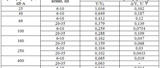
When commissioning current transformers, fresh dry transformer oil before and after filling (topping up) into transformers must be tested in accordance with the requirements of Section 25. During operation, transformer oil from current transformers with voltages up to 35 kV inclusive may not be tested. Oil from current transformers 110-220 and 330-500 kV, not equipped with an operating voltage control system, is tested in accordance with the requirements of paragraphs. 1-3 tables 25.4 taking into account section. 25.3.2 – once every 2 years (for sealed current transformers – according to the manufacturer’s instructions). Oil from current transformers equipped with a control system under operating voltage, when the controlled parameters reach the limit values given in table. 4, tested according to the requirements of table. 25.4 (clauses 1-7).
Table 4
| Voltage class, kV | Limit values, %, of parameters δtgδ and δY/Y | |
| with periodic monitoring | with continuous monitoring | |
| 220 | 2,0 | 3,0 |
| 330-500 | 1,5 | 2,0 |
| 750 | 1,0 | 1,5 |
For oil-filled cascade current transformers, the condition of the transformer oil in each stage is assessed according to standards corresponding to the operating voltage of the stage.
Determination of the load on current transformers for relay protection
The load on the CT for relay protection consists of series-connected resistances of relay equipment, connecting wires and transition resistances in contact connections. The magnitude of the secondary load also depends on the CT connection diagram and on the type of short circuit.
Relay protection under short-circuit conditions usually operates at high currents, which are many times higher than the rated current of the CT. Calculations and operating experience have established that to ensure proper operation of relay protection, CT errors should not exceed the maximum permissible values.
According to the PUE, this error, as a rule, should not be more than 10%.
In GOST 7746-88, the accuracy of CTs used for relay protection is normalized by their total error (ε), caused by the magnetizing current. According to the condition ε < 10%, the curves of the maximum CT multiplicities were constructed.
In this case, the largest ratio of the primary current to its rated value, at which the total error at a given secondary load does not exceed 10%, is called the maximum factor (K10).
According to the same GOST, CT supply plants are required to guarantee the value of the nominal maximum multiplicity (K10n), at which the total error of a CT operating with a rated secondary load does not exceed 10%.
To find the permissible load using the maximum multiplicity curves, it is necessary to first determine the calculated short-circuit current multiplicity, i.e., the ratio of the short-circuit current at the design point to the minimum CT current (Colorful)
Removing magnetization characteristics
The characteristic is removed by increasing the voltage on one of the secondary windings until saturation begins, but not higher than 1800 V. If the windings have branches, the characteristic is removed on the working branch. During operation, only three control points can be removed. The taken characteristic is compared with the typical magnetization characteristic or with the magnetization characteristics of serviceable current transformers of the same type as those being tested. Differences from the values measured at the manufacturer or from those measured on a working current transformer of the same type as the one being tested should not exceed 10%.
6. Determination of the design load Zн
The design load for relay protection current transformers is determined using the expressions given in Table No. 1. The calculation assumes Zн=Zadd.
By the value of Zn you can determine the resistance of the connecting wires (cable cores) in the secondary circuits of current transformers.
Table 1 - calculation formulas for determining the secondary load and resistance of the connecting wires of current transformers for relay protection
Measuring and calculating the limiting factor
When the maximum normalized indicator is exceeded, the device moves from the stable operating area to the saturation phase. The accuracy of the functional is assessed using mathematical curves, the conditions of which are given in the tables. The coefficient is not established empirically, but according to special tabular data. The curves consist of information about the largest ratio of secondary current to the average rated current supplied to the primary.
The calculation is made in such a way that the total error in the calculated data (that is, when including the specified information about the secondary load) does not exceed ten percent. Mathematical curves allow you to calculate the characteristics of wires, devices, relays, connection diagrams and create a circuit in such a way that oversaturation does not occur and the devices operate in optimal mode.
Equipment supplemented with differential protection must have an identical maximum multiplicity for through short-circuit current.
Design curves are given for calculations of work according to the established mode. If the aperiodic tends to max, that is, the mode is transitional, then the parameter reaches 70-75%.
The accuracy class is chosen depending on the purpose. The same requirements apply to devices with non-identical load types.
7. Determination of the resistance of connecting wires
Table No. 1 shows calculated expressions for determining the resistance of connecting wires in the secondary circuits of current transformers, depending on their connection diagrams and the type of short circuit.
In this case, the resistance of the relay equipment connected to the current transformers can be found using Reference data on the consumption of relay equipment or other factory data.
Based on the found value of rpr, the permissible cross-section of the connecting wires is determined.
If, as a result of the calculation, S turns out to be less than 2.5 mm2, then it should be taken equal to 2.5 mm2 from the condition of the mechanical strength of the wires in the CT current circuits, after which the actual resistance of the wires is determined by expression (2).
If, as a result of the calculation, the cable cross-section turns out to be excessively large (more than 10 mm2), then the following measures can be recommended to reduce it:
1. Apply a series connection of two windings of the current transformers of the protection in question. When identical current transformer cores are connected in series, the load on each CT core is reduced by 2 times. When different current transformer cores are connected in series, the calculated load on the CT is reduced, since it is distributed between the windings of the current transformers in proportion to their EMF.
2. Change the connection diagram of the current transformers instead of an incomplete star, go to a full star; instead of a current difference circuit, go to a partial star circuit, etc.
3. Use another current transformer that allows a larger secondary load.
4. Install an additional set of current transformers and transfer part of the secondary load to it.
CT error limits for classes P
All characteristics are indicated in the documentation for specific types of devices. Also, information is registered separately for each device. Specifically for accuracy classes P, limits of permissible current and angular errors are established.
For transformers with power class 5P at a normal current with a maximum full multiple of 5 percent, the permissible error limits are as follows:
- current – + or – 1%;
- angular + or - 60 percent, which is identical to 1.9.
The limits indicated in the tables are met, since this is the first of the safety requirements.
For a device of accuracy class 10P, the required maximum factor is 10%, respectively. The maximum possible error limit during operation is 3 percent. At the same time, data on angular errors is not presented, since they are not standardized.