Operating mode of power transformers and voltage regulation in distribution networks
Typical TP (RTP) designs provide for separate operation of transformers on the HV and LV sides, but in some cases it may be necessary to switch on transformers for parallel operation (parallel connection of both primary and secondary windings).
Parallel operation of transformers is allowed provided that: the connection groups of the transformer windings are identical; equality of transformation ratios of transformers; equality of short circuit voltages (SH) of transformers. Parallel operation of transformers with a rated power ratio of more than 3 is not recommended.
Turning on transformers for parallel operation is possible only after preliminary hot phasing on the LV side using an indicator with a luminous scale or a voltmeter. The phases of the transformers are considered to be the same if the voltmeter or indicator readings on the phases of the same name are zero.
An example of “hot” phasing of 2 power transformers with grounded neutral points of the secondary windings and identical connection groups Y/Yh-0 (or D/Yh-1 1) is shown in Fig. 1.
The voltage is measured first between phases of the same name, and then between phases of the same name (see table)
Table of measured voltages
| Voltage between terminals | |||
| Phase shift | a1 -a2 | a1- b2 | a1 - c2 |
| (hours) | v1 - v2 | в1 -с2 | в1 -а2 |
| c1 -c2 | c1 - a2 | c1 -b2 | |
| Ul | Ul |
In the example given, parallel operation is possible by connecting terminals of the same name.
Load capacity of power transformers
(in accordance with GOST, PUE and PTE)
For transformers, depending on operating conditions determined by the load schedule and t° of the cooling medium, emergency and systematic overloads are allowed. In emergency cases, oil transformers with cooling systems M and D allow one of the following short-term overloads in excess of the rated current (regardless of the duration of the previous load, the temperature of the cooling medium and the installation location)
30% - within 120 minutes. 75% - within 20 minutes. 45% - within 80 minutes. 100% - within 10 minutes. 60% within 45 min.
In emergency cases, if the initial load factor is not more than 0.93, oil transformers with a cooling system M and D allow an overload of 40% above the rated current for no more than 5 days during peak loads for a total duration of no more than 6 hours per day M - natural circulation of oil and air
D - natural oil circulation and forced air circulation.
At rated load, the temperature of the upper layers of oil should be no higher than 95 C for oil transformers with an M or D cooling system. For oil transformers, a long-term overcurrent of 5% of the rated branch current is allowed if the voltage on the branch does not exceed the rated one.
In emergency cases, dry transformers allow the following short-term overloads in excess of the rated current, regardless of the previous load and the temperature of the cooling medium 20% - for 60 minutes. 50% - within 18 minutes. 30% - within 45 minutes. 60% - within 5 minutes. 40% - within 32 minutes. Permissible long-term overloads of dry-type transformers are established by the factory instructions.
Taking into account the above values of short-term overloads of oil and dry transformers, the mode of maximum permissible (calculated according to the project) transformer overloads in a 2-beam network diagram is selected.
For oil transformers - 140% For dry transformers - 120%
Ventilation of transformer rooms must ensure the removal of heat generated by them in such quantities that when they are loaded, taking into account the overload capacity and the maximum design ambient temperature, the heating of the transformers does not exceed the maximum permissible values. Ventilation of transformer rooms must be carried out in such a way that the temperature difference between the air leaving the room and entering it does not exceed 15°C.
Voltage regulation
According to GOST 13109-97 “Electric energy quality standards in general-purpose power supply systems,” normally permissible steady-state voltage deviations at the terminals of electrical receivers must be within ±5% of the rated voltage (380/220 V; 6 and 10 kV), and the maximum permissible steady-state deviations - ±10% (in abnormal network operating modes). Based on these standards, the voltage at the control points of the network, ensuring permissible voltage levels at electrical receivers, must be within the following limits: at the entrance to the building: from 368/214 V (-3%) to 400/230 V (+5%) at the assembly n/n in TS: from 380/220 V (Unom) to 400/230 V (+5%) on kV buses of TS (RP) from 6 kV (Unom) to 6.6 kV (+10%)
from 10 kV (Inom) to 10.6 kV (+6%)
The main reasons for voltage deviation from acceptable values may be: voltage deviation from the approved daily schedule on the 6-10 kV CPU buses; the occurrence of technological disturbances in the electrical networks of electrical networks and consumers; improper use of control devices of network transformers of electrical networks, consumers; the absence of stabilizing devices in the electrical network of consumers with power receivers that worsen the quality of electricity in external power supply networks; non-compliance of internal power supply schemes with the requirements of the PUE; other. When consumer complaints about the quality of voltage are received by the electrical network district, the reasons for the deviation must be established as soon as possible and measures must be taken to eliminate them (elimination of faults in the electrical networks, switching branches of the windings of network transformers, changing the power supply circuit of the network section, bringing the voltage on the busbars to 6-10 kV CPU to the approved daily schedule and others). In some cases, electrical network personnel must install PKE monitoring devices at network control points in order to determine the causes of unacceptable voltage deviations. Upon completion of the measures, a 2-sided Voltage Quality Check Report is drawn up at the current distribution point of the network between the electrical networks and the consumer. When receiving mass consumer complaints about voltage increased beyond permissible deviations and the inability of the CPU staff to restore normal voltage (within the daily schedule), the operational personnel of electrical networks are obliged to do so as soon as possible. when the voltage increases above 3% of the approved daily schedule, transfer the power supply to consumers to other CPUs;
Load capacity of power transformers.
⇐ PreviousPage 3 of 8Next ⇒The normal operating mode of transformers is, first of all, the nominal mode with all nominal parameters. If the deviations of the parameters are within acceptable limits, then such modes will also be acceptable and normal.
PTE: Continuous operation of the transformer is allowed (at a power not exceeding the rated one) at a voltage on any branch 10% higher than the rated one. In this case, the voltage on any winding should not be higher than the maximum operating voltage.
The upper limit of the voltage increase is determined by the need to limit the heating of the transformer by losses in the steel, which are proportional to the square of the magnetic induction or the square of the voltage. The reactive component of the cold current increases sharply. when working on the nonlinear part of the magnetization characteristic, losses in the winding from cold currents increase.
According to the conditions of electrical insulation strength, Uwork.max cannot be exceeded:
Insulation class, kV 6 10 20 35 110 220 330 500 750
U work.max, kV 6.9 11.5 23 40.5 126 252 363 525 787
U operating max/ U nom 1.15 1.15 1.15 1.15 1.15 1.15 1.1 1.05 1.05
Thus, even a 10% increase in voltage is not always acceptable.
PTE: For transformers, long-term overcurrent of any winding is allowed by 5% of the rated branch current, if the voltage does not exceed the rated one.
Calculations show that when the current changes by 1%, the winding temperature increases by (1.4 -1.6) ° C, thus increasing insulation wear. If T constantly worked with such an overload, its service life would decrease by more than 2 times. Considering that the loads T change, part of the time T works with underload, and overloads are also possible.
Load capacity T is the totality of permissible loads and overloads.
The permissible load is a long-term load at which the calculated wear of the winding insulation from heating does not exceed the wear corresponding to the nominal operating mode. Permissible systematic loads T greater than the rated power are possible due to the unevenness of the load curve.
Systematic loads make it possible to reduce the underutilization of transformers and reduce the installed power. In this case, as a rule, the maximum load should not exceed 1.5 Snom, the oil temperature in the upper layers should not exceed 95 ° C, and the winding temperature at the hottest point should not exceed 140 ° C. In this mode, the transformer can operate for the entire service life.
In emergency overload mode, the insulation wear exceeds the nominal value. Typically, the overload is no more than 2.0 S nom, the oil temperature in the upper layers is no more than 115 ° C, the maximum winding temperature for T with a rated voltage up to 110 kV is no more than 160 ° C, for T with a rated voltage above 110 kV - 140 ° WITH. This mode is allowed in exceptional cases for a limited time to ensure reliability of power supply.
Let us consider in more detail the mode of systematic loads greater than the rated power. In Fig. Figure 3 shows the daily load graph T.
Fig.3 Fig.4
If you choose a rated power greater than the maximum load, T will be underloaded for most of the day. When choosing S nom according to the schedule (Fig. 3), T will be overloaded by 1.25 times within two hours and by 1.05 times within another 4 hours.
The acceptance criterion is the wear of the insulation. Calculations are related to thermal calculation of T, determination of temperatures, the nature of their changes, etc. The amount of computational work is large. In practice, they use calculation tables compiled for two-stage graphs with parameters K
1,
K
2 and
h
(Fig. 4). The predefined daily schedule must be converted into an equivalent (in terms of wear) two-stage schedule.
The conversion order is as follows:
The area of time overload h
=Δ
h
1 +Δ
h
2+…..
Load values S
1
*, S
2
*,…
for each interval Δ
h
For the rest of the graph, determine the intervals Δ t
1, Δ
t
2,... and the corresponding load values
S
1,
S
2...in these intervals. The initial load coefficient is determined as the root-mean-square value according to the expression:
.
The maximum load coefficient in the interval h is determined similarly
.
If K2* ≥ 0.9 Kmax, then take K2 = K2*, if K2* ≤ 0.9 Kmax, then take
K2 =0.9Kmax (Kmax = Smax/Snom).
Knowing the average temperature of the cooling medium during the duration of the schedule, the cooling system T, according to the tables given in GOST, determines the permissibility of the relative load K2 and its duration (Table 1).
A load of more than 1.5 Snom must be agreed with the manufacturer; a load more than 2.0 Snom is not allowed.
Table 1
Systematic overloads
| h ,h | M and D | DC iC | ||||||||||||||
| K2 at values K1 =0.25-0.1 | K2 at values K1 =0.25-0.1 | |||||||||||||||
| 0,2 | 0,4 | 0,5 | 0,6 | 0,7 | 0,8 | 0,9 | 1,0 | 0,25 | 0,4 | 0,5 | 0,6 | 0,7 | 0,8 | 0,9 | 1,0 | |
| 0,5 | + | + | + | + | + | + | + | 1,84 | 1,711 | 1,699 | 1,677 | 1,644 | 1,61 | 1.57,57 | 1,52 | 1,44 |
| 1,0 | + | + | + | 2,00 | 1,94 | 1,86 | 1,76 | 1,60 | 1,57 | 1,55 | 1,54 | 1,52 | 1,49 | 1,46 | 1,42 | 1,35 |
| 2,0 | 1,76 | 1,73 | 1,70 | 1,67 | 1,63 | 1,58 | 1,51 | 1,40 | 1,41 | 1,40 | 1,39 | 1,38 | 1,36 | 1,34 | 1,31 | 1,26 |
| 4,0 | 1,46 | 1,44 | 1,43 | 1,14 | 1,39 | 1,36 | 1,32 | 1,25 | 1,28 | 1,27 | 1,27 | 1,26 | 1,25 | 1,24 | 1,22 | 1,19 |
| 6,0 | 1,33 | 1,32 | 1,31 | 1,30 | 1,29 | 1,27 | 1,24 | 1,20 | 1,21 | 1,21 | 1,21 | 1,20 | 1,20 | 1,19 | 1,18 | 1,15 |
| 8,0 | 1,26 | 1,26 | 1,25 | 1,24 | 1,23 | 1,22 | 1,20 | 1,17 | 1,18 | 1,18 | 1,17 | 1,17 | 1,17 | 1,16 | 1,15 | 1,13 |
| 12,0 | 1,19 | 1,19 | 1,18 | 1,18 | 1,17 | 1,16 | 1,15 | 1,13 | 1,14 | 1,14 | 1,14 | 1,13 | 1,13 | 1,13 | 1,12 | 1,11 |
| 24,0 | 1,08 | 1,08 | 1,08 | 1,08 | 1,08 | 1,08 | 1,08 | 1,08 | 1,07 | 1,07 | 1,07 | 1,07 | 1,07 | 1,07 | 1,07 | 1,07 |
Θ 0 = 10° C
θо=20°С
| h ,h | M and D | DC iC | ||||||||||||||
| K2 at values K1 =0.25-0.1 | K2 at values K1 =0.25-0.1 | |||||||||||||||
| 0,25 | 0,4 | 0,5 | 0,6 | 0,7 | 0,8 | 0,9 | 1,0 | 0,25 | 0,4 | 0,5 | 0,6 | 0,7 | 0,8 | 0,9 | 1,0 | |
| 0,5 | + | + | + | + | + | 1,98 | 1,81 | 1,00 | 1,63 | 1,60 | 1,58 | 1,55 | 1,52 | 1,47 | 1,41 | 1,00 |
| 1,0 | 1,97 | 1,92 | 1,87 | 1,80 | 1,71 | 1,57 | 1,00 | 1,49 | 1,47 | 1,45 | 1,43 | 1,40 | 1,37 | 1,31 | 1,00 | |
| 2,0 | 1,66 | 1,63 | 1,60 | 1,56 | 1,51 | 1,45 | 1,35 | 1,00 | 1,34 | 1,33 | 1,32 | 1,30 | 1,28 | 1,26 | 1,22 | 1,00 |
| 4,0 | 1,37 | 1,35 | 1,34 | 1,32 | 1,29 | 1,25 | 1,19 | 1,00 | 1,21 | 1,20 | 1,19 | 1,19 | 1,18 | 1,16 | 1,13 | 1,00 |
| 6,0 | 1,25 | 1,24 | 1,23 | 1,21 | 1,20 | 1,17 | 1,13 | 1,00 | 1,15 | 1,14 | 1,13 | 1,13 | 1,13 | 1,12 | 1,10 | 1,00 |
| 8,0 | 1,18 | 1,17 | 1,17 | 1,16 | 1,15 | 1,13 | 1,09 | 1,00 | 1,11 | 1,11 | 1,10 | 1,10 | 1,10 | 1,09 | 1,07 | 1,00 |
| 12,0 | 1,11 | 1,10 | 1,10 | 1,09 | 1,09 | 1,08 | 1,06 | 1,00 | 1,07 | 1,07 | 1,07 | 1,06 | 1,06 | 1,05 | 1,04 | 1,00 |
| 24,0 | 1,00 | 1,00 | 1,00 | 1,00 | 1,00 | 1,00 | 1,00 | 1,00 | 1,00 | 1,00 | 1,00 | 1,00 | 1,00 | 1,00 | 1,00 | 1,00 |
θcool=30°С θcool=40°С
| h ,h | K1 |
| 0,4 | 0,5 |
| 1,26 | 1,24 |
| 1,15 | 1,13 |
| h ,h | K1 |
| 0,4 | 0,5 |
| 1,17 | 1,15 |
| 1,05 | 1,03 |
As an example, let us calculate the possibility of a systematic load greater than the rated one if the transformer has a daily schedule shown in Fig. 3.
We determine by the given formulas K1 = 0.404, K2* = 1.12,
K2 =0.9 K max = 0.9 *25/20 =1.125, so we take K2 = 1.125, h=6 h.
From Table 1 we find that at θ 0 = 10°C at K1 = 0.4 and h = 6 hours, K2add = 1.32.
At θ 0 =20°C K2add = 1.24, at θ0 =30°C K2add = 1.15 and only at θ0 =40°C K2add = 1.05, which is greater than the calculated value.
Emergency overloads most often occur when a parallel operating T fails.
In emergency overload mode, the insulation wear exceeds the nominal value. Typically, the overload is no more than 2.0 S nom, the oil temperature in the upper layers is no more than 115 ° C, the maximum winding temperature for T with a rated voltage of up to 110 kV is no more than 160 ° C, for T with a rated voltage above 110 kV - 140 ° C WITH. This mode is allowed in exceptional cases for a limited time to ensure reliability of power supply.
The value of the permissible emergency overload can be determined from the tables according to GOST (example table 2). Analyzing the data in the table, we can conclude that with an initial load of no more than 0.9 Snom, transformers of all types allow an overload of 40% for 6 hours at θ 0 no more than +20°C and 30% for 6 hours at θ 0 +30° C.
table 2
Emergency overloads
θcool=20◦С
| h ,h | M and D | DC iC | ||||||||||||||
| K2 at values K1 =0.25-0.1 | K2 at values K1 =0.25-0.1 | |||||||||||||||
| 0,25 | 0,4 | 0,5 | 0,6 | 0,7 | 0,8 | 0,9 | 1,0 | 0,25 | 0,4 | 0,5 | 0,6 | 0,7 | 0,8 | 0,9 | 1,0 | |
| 0,5 | 2,00 | 2,00 | 2,00 | 2,00 | 2,00 | 2,00 | 2,00 | 2,00 | 1,70 | 1,70 | 1,70 | 1,70 | 1,70 | 1,60 | 1,60 | 1,50 |
| 1,0 | 2,00 | 2,00 | 2,00 | 2,00 | 2,00 | 2,00 | 1,80 | 1,80 | 1,60 | 1,60 | 1,60 | 1,60 | 1,60 | 1,50 | 1,50 | 1,50 |
| 2,0 | 1,80 | 1,80 | 1,80 | 1,80 | 1,70 | 1,70 | 1,70 | 1,60 | 1,50 | 1,50 | 1,50 | 1,50 | 1,50 | 1,40 | 1,40 | 1,40 |
| 4,0 | 1,50 | 1,50 | 1,50 | 1,50 | 1,50 | 1,40 | 1,40 | 1,40 | 1,40 | 1,40 | 1,40 | 1,40 | 1,40 | 1,40 | 1,40 | 1,40 |
| 6,0 | 1,40 | 1,40 | 1,40 | 1,40 | 1,40 | 1,40 | 1,40 | 1,30 | 1,40 | 1,40 | 1,40 | 1,40 | 1,40 | 1,40 | 1,40 | 1,40 |
| 8,0 | 1,30 | 1,30 | 1,30 | 1,30 | 1,30 | 1,30 | 1,30 | 1,30 | 1,40 | 1,40 | 1,40 | 1,40 | 1,40 | 1,40 | 1,40 | 1,40 |
| 12,0 | 1,30 | 1,30 | 1,30 | 1,30 | 1,30 | 1,30 | 1,30 | 1,30 | 1,40 | 1,40 | 1,40 | 1,40 | 1,40 | 1,40 | 1,40 | 1,40 |
| 24,0 | 1,30 | 1,30 | 1,30 | 1,30 | 1,30 | 1,30 | 1,30 | 1,30 | 1,40 | 1,40 | 1,40 | 1,40 | 1,40 | 1,40 | 1,40 | 1,40 |
θcool=30◦С
| h ,h | M and D | DC iC | ||||||||||||||
| K2 at values K1 =0.25-0.1 | K2 at values K1 =0.25-0.1 | |||||||||||||||
| 0,25 | 0,4 | 0,5 | 0,6 | 0,7 | 0,8 | 0,9 | 1,0 | 0,25 | 0,4 | 0,5 | 0,6 | 0,7 | 0,8 | 0,9 | 1,0 | |
| 0,5 | 2,00 | 2,00 | 2,00 | 2,00 | 2,00 | 2,00 | 2,00 | 1,90 | 1,70 | 1,60 | 1,60 | 1,60 | 1,60 | 1,50 | 1,50 | 1,50 |
| 1,0 | 2,00 | 2,00 | 2,00 | 2,00 | 1,90 | 1,90 | 1,80 | 1,70 | 1,50 | 1,50 | 1,50 | 1,50 | 1,50 | 1,50 | 1,40 | 1,40 |
| 2,0 | 1,80 | 1,70 | 1,70 | 1,70 | 1,60 | 1,60 | 1,50 | 1,40 | 1,40 | 1,40 | 1,40 | 1,40 | 1,40 | 1,40 | 1,40 | 1,40 |
| 4,0 | 1,40 | 1,40 | 1,40 | 1,40 | 1,40 | 1,30 | 1,30 | 1,30 | 1,30 | 1,30 | 1,30 | 1,30 | 1,30 | 1,30 | 1,30 | 1,30 |
| 6,0 | 1,30 | 1,30 | 1,30 | 1,30 | 1,30 | 1,30 | 1,30 | 1,20 | 1,30 | 1,30 | 1,30 | 1,30 | 1,30 | 1,30 | 1,30 | 1,30 |
| 8,0 | 1,20 | 1,20 | 1,20 | 1,20 | 1,20 | 1,20 | 1,20 | 1,20 | 1,30 | 1,30 | 1,30 | 1,30 | 1,30 | 1,30 | 1,30 | 1,30 |
| 12,0 | 1,20 | 1,20 | 1,20 | 1,20 | 1,20 | 1,20 | 1,20 | 1,20 | 1,30 | 1,30 | 1,30 | 1,30 | 1,30 | 1,30 | 1,30 | 1,30 |
| 24,0 | 1,20 | 1,20 | 1,20 | 1,20 | 1,20 | 1,20 | 1,20 | 1,20 | 1,30 | 1,30 | 1,30 | 1,30 | 1,30 | 1,30 | 1,30 | 1,30 |
It should be noted that all tables are suitable for transformers with a power of up to 100 MVA and a voltage of up to 110 kV.
Currently, there are additional technical conditions for permissible overloads of transformers. Thus, with a previous load of no more than 0.8 nominal and a cooling air temperature of 20 ° C, overloads of 1.4 are allowed for 4 hours, and for autotransformation -
tors at a previous load of 0.7 S nom at θ 0 = 25° C, the following multiplicities and durations of overloads are allowed:
1.0 h – 1.4; 2.0 h 1.3; 4.0 h 1.2.
There are also special calculation tables that can be used to determine insulation wear during emergency overload. So, working for 4 hours with an overload of 40% and a previous load of 0.8 Snom at an air temperature of 20°C will lead to insulation wear in 200 hours, and at an ambient temperature of 30°C, insulation wear will be 600 hours, i.e. 5 days.
Another type of overload is short-term overload that occurs in emergency and post-emergency modes during the operation of automation devices. The admissibility criterion is only the maximum permissible temperatures of the windings and oil (Fig. 5).
Fig.5
PTE: Short-term overloads of oil transformers in excess of the rated current are allowed for all cooling systems, regardless of the duration and value of the previous load and the temperature of the cooling medium within the following limits:
Overload, % 30 45 60 75 100
Duration, min 10
One more note:
At ambient temperatures higher than nominal, i.e. more than 20° C, the transformer cannot operate for a long time at the rated load without increased wear of the insulation. It is necessary to reduce the load or take additional cooling measures, for example, spraying coolers, wetting radiators. On the contrary, at low temperatures, the load T can be increased, while the wear of the insulation will not exceed normal, and all temperatures will not exceed permissible limits. The factory instructions provide such tolerances.
Table 3 shows an example of permissible loads (in pu) depending on the ambient temperature.
Table 3
| Θ0, ° | |||
| TO | 1,15 | 1,08 | 0,83 |
⇐ Previous3Next ⇒
Conflicts in family life. How can I change this? It is rare that a marriage and relationship exists without conflict and tension. Everyone goes through this...
What makes your dreams come true? One hundred percent, unshakable confidence in your...
WHAT IS CONFIDENT BEHAVIOR IN INTERPERSONAL RELATIONSHIPS? Historically, there are three main patterns of differences that exist between...
WHAT HAPPENS IN ADULT LIFE? If you are still connected to your mother in the wrong way, you are avoiding separation and independent adult existence...
Didn't find what you were looking for? Use Google search on the site:
Transformer overload – a mode that shortens the life of the device
A transformer is an electrical device used to convert alternating current from one voltage to another. The operating principle is based on electromagnetic induction.
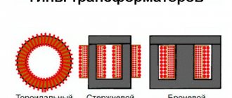
What types of transformers are there?
Types of transformers
Transformers differ in technical characteristics and purpose; they are divided into several types, these are:
- Power – used to convert electrical energy in electrical networks of various voltages (0.4/10.0/35.0/110.0/220.0/500.0/1150.0 kV) with an industrial frequency of 50 Hz. They are installed at transformer substations and specially equipped foundations and sites. They differ in the design of the cooling system (oil and dry), the number of windings (2, 3 or more windings).
- Network - used to supply power to low-voltage appliances, household and other devices. They differ in the number of windings on the secondary side and the output voltage (from 1.5 to 127.0 V), the primary voltage being 220 V. These are low-frequency transformers.
- Autotransformers - a distinctive feature of these devices is that one winding is part of the second (primary secondary or secondary primary), making it possible to adjust the voltage on one of the windings.
- Current transformers are devices whose primary winding is connected to the power supply circuit of an electrical energy source, and devices designed for lower currents are connected to the secondary winding. Used in electrical energy metering and control systems. Available for all voltage classes. The main technical characteristic is the transformation ratio, defined as the ratio of the current in the primary winding to the current in the secondary winding. They differ in accuracy class, differ in the type of insulation (oil, cast, gas, dry), according to the principle of current conversion (electromagnetic, electro-optical, magneto-semiconductor), according to the design of the primary winding (coil, feed-through, busbar), according to placement conditions and the type of transformed quantities.
- Voltage and measuring transformers are similar in principle to power transformers. The difference is in purpose - they are used in systems for accounting and quality control of electrical energy.
Principle of operation
The operation of the transformer is based on the principle of electromagnetic induction, which is created in the magnetic core of the device.
Electromagnetic induction occurs under the influence of an electric current passing in the primary winding of a device, and through it an electric current arises in the secondary winding.
Primary and secondary winding of the device
Main characteristics
Power – determines the amount of power consumers that can be connected to this device in normal operation;
Voltage – determines the characteristics of the electrical network for which the device is intended.
Transformer operating modes
- Operating mode – when the device operates in accordance with the specified technical parameters and in accordance with the requirements.
- Idling mode - in this operating mode, no-load current flows in the primary winding, the secondary network is open (no load);
- Short circuit mode is an emergency operating mode, characterized by a short circuit of the secondary winding.
Another mode that may arise during operation is an overload mode, which is not yet characterized by a short circuit mode, but, nevertheless, by parameters that do not correspond to the operating mode.
Transformer overload, its types
The totality of permissible loads and overloads determines the load capacity of the transformer.
Permissible load - a load corresponding to the nominal operating mode, unlimited in time, at which the winding insulation does not wear out due to heating during operation.
Overload is an operating mode caused by connecting a load power greater than the rated one or an ambient temperature greater than the calculated one. When overloaded, accelerated wear of the winding insulation occurs.
There are overloads:
- Systematic – caused by the daily work schedule. Such operating modes must correspond to the permissible overload factors and their passage time for each specific device.
- Emergency – caused by emergency situations. Overloads of this type are:
- Short term;
- Long lasting.
Overloading oil transformers
An oil transformer is a power unit that uses oil as a coolant.
The operating mode of devices of this type is regulated by GOST 14209-97 (IEC354-91) “Guidelines for the loading of power oil transformers,” which came into force in 2001.
Temperature and current limits for overload mode:
| Load type | Transformers | ||
| Distribution | medium power | High power | |
| Systematic | |||
| Electric current values (relative units) | 1,5 | 1,5 | 1,3 |
| Temperature of the hottest area, °C | 140 | 140 | 120 |
| Temperature of the cooling agent (oil) in the upper layer, °C | 105 | 105 | 105 |
| Emergency, long-term | |||
| Electric current values (relative units) | 1,8 | 1,5 | 1,3 |
| Temperature of the hottest area, °C | 150 | 140 | 130 |
| Temperature of the cooling agent (oil) in the upper layer, °C | 115 | 115 | 115 |
| Emergency, short-term | |||
| Electric current values (relative units) | 2,0 | 1,8 | 1,5 |
| Temperature of the hottest area, °C | See notes | 160 | 160 |
| Temperature of the cooling agent (oil) in the upper layer, °C | See notes | 115 | 115 |
When choosing the power of transformers, you cannot be guided only by their rated power, since in real conditions the temperature of the cooling medium and the conditions for installing the transformer may be different from the accepted ones. The load on the transformer changes throughout the day, and if the power is selected according to the maximum load, then during periods of decline the transformer will not be loaded, i.e. its power is underutilized. Operating experience shows that a transformer can operate part of the day with an overload, if in another part of the day its load is less than the rated load. The criterion for various modes is the wear of the transformer insulation.
Transformer load capacity
The load capacity of a transformer is a combination of permissible loads and overloads.
The permissible load is a long-term load at which the calculated wear of the winding insulation from heating does not exceed the wear corresponding to the rated operating mode.
Transformer overload is a mode in which the calculated wear of the winding insulation exceeds the wear corresponding to the nominal operating mode. This mode occurs if the load is greater than the rated power of the transformer or the temperature of the cooling medium is greater than the accepted design one.
Fig.1. Construction of a two-stage graph based on the daily load graph of the transformer
Permissible systematic loads
Permissible systematic loads of a transformer greater than its rated power are possible due to load unevenness during the day. Figure 1 shows a daily load graph, from which it can be seen that at night, morning and daytime hours the transformer is underloaded, and during the evening peak it is overloaded. During underload, insulation wear is small, but during overload it increases significantly. The maximum permissible systematic load is determined on the condition that the highest winding temperature is +140°C, the highest oil temperature in the upper layers is +95°C and insulation wear during the maximum load is the same as when the transformer operates at a constant rated load, when the temperature is the hottest points does not exceed +98°С (GOST 14209-85). To calculate the permissible systematic load, the actual schedule is converted into a two-stage one (see Fig. 1).
The initial load coefficient of the equivalent schedule is determined by the expression
where s1,s2,…,sm are load values in the intervals Δt1, Δt2,…,Δtm.
Maximum load coefficient in the interval h=Δh1+Δh2+…+Δhp.
If K'2≥0.9Kmax, then take K'2=K2, if K'2max, then take K2=0.9Kmax.
Knowing the average temperature of the cooling medium during the duration of the schedule (0oxt), the cooling system of the transformer (M, D, DC, Ts), according to the tables given in GOST 14209-85 (for transformers up to 100 MBA), determine the permissibility of the relative load K2 and its duration.
Loads greater than 1.5 Snom must be agreed upon with the manufacturer. A load of more than 2.0 Snom is not allowed.
Emergency overload is permitted in emergency cases, for example, when a parallel-connected transformer fails.
The permissible emergency overload is determined by the maximum permissible winding temperatures (140°C for transformers with voltages above 110 kV and 160°C for other transformers) and the oil temperature in the upper layers (115°C). Emergency overloads cause increased wear of the turn insulation, which can lead to a reduction in the normal service life of the transformer if the increased wear is not subsequently compensated by a load with insulation wear below normal.
The value of the permissible emergency overload is determined according to GOST 14209-85 depending on the initial load coefficient K1, the temperature of the cooling medium at the time of the emergency overload 0okhl and the duration of the overload. The maximum emergency overload should not exceed 2.0 Snom.
When choosing transformers installed at substations based on emergency overload conditions, you can use Table 1.
Table 1
Permissible emergency overloads of transformers when choosing their rated power for industrial substations with a previous load not exceeding 0.8 (according to GOST 14209-85)
An accurate calculation of the maximum permissible loads and emergency overloads, as well as the wear of the coil insulation, is carried out on a computer according to the auxiliary diagrams given in GOST 14209-85.
Analyzing the tables of permissible emergency overloads given in GOST 14209-85, we can conclude that transformers with cooling systems M, D, DC and Ts with an initial load of no more than 0.9 Snom allow an overload of 40% for 6 hours at a cooling air temperature of no more than + 20°C and 30% for 4 hours at a cooling air temperature of +30°C.
Permissible loads and emergency overloads for transformers with a power over 100 MBA are established in the operating instructions; for dry transformers and transformers with non-flammable liquid dielectric - in standards or technical specifications for specific types of transformers (GOST 11677-85).
Selecting power transformer power
Selecting power transformer power
A rational power supply scheme depends on a technically sound selection of transformer power, which affects operating costs and payback, which is possible in 6–10 years.
When choosing a transformer, they are guided by the following criteria:
- Power supply category
– the number of transformers is determined. Objects of power supply category III – one transformer. Objects of II and I categories of power supply - two or in some cases three transformers. - Overload capacity
- determination of the power of the transformer. - Daily load distribution schedule
– recording loads by time and days of the week. - Economical mode of operation of the plant.
Selecting the number of transformers
Single-transformer substations are used in two cases. Firstly, for objects of category III power supply. Secondly, for consumers who have the ability to back up power supply using ATS (automatic transfer switch) from another power source.
When supplying consumers of categories I and II in emergency mode at a two-transformer substation, after the ATS is triggered, the entire transformer takes on the load of the faulty one. Therefore, its overload capacity should be sufficient to replace a failed transformer. In normal mode, transformers operate underloaded, which is not economically feasible. Therefore, in an emergency, some consumers of category III power supply are disconnected from the network.
The power supply break for category II facilities is limited to one day. To restore the scheme, a strategic warehouse reserve of equipment necessary to eliminate the accident is required. In this case, the power of the new transformer must be identical to the one being replaced. Thus, the amount of backup equipment is reduced.
How to choose a power transformer by power
Collection and analysis of the power of consumers powered from one transformer is not always sufficient.
For production facilities, they follow the procedure for putting equipment into operation. It is taken into account that all consumers cannot be turned on at the same time. However, possible increases in production capacity are also taken into account.
Therefore, when calculating and choosing the power of a power transformer, they are guided by the schedule of the average daily and total active load of the substation, as well as the duration of the maximum load. If a transformer is being calculated that will participate in the power supply of residential infrastructure, then the time of year is also taken into account. In winter, the load increases due to the inclusion of electric heating, in summer - air conditioning.
Table No. 1 - Selection of power transformer by power and permissible emergency loads
| Type of load | Load intervals (kVA) for transformers with power (kVA) | |||||||
| 25 | 40 | 63 | 100 | 160 | 250 | 400 | 630 | |
| Industrial consumers, household yards, workshops for servicing agricultural machinery, construction shops, vegetable storage and water supply pumping stations, boiler houses | up to 42 | 43-68 | 69-107 | 108-169 | 170-270 | 271-422 | 423-676 | 677-1064 |
| Municipal consumers - public and administrative enterprises (schools, clubs, canteens, baths, shops) in combination with residential buildings | up to 44 | 45-70 | 71-110 | 111-176 | 177-278 | 279-435 | 436-696 | 697-1096 |
| Rural residential buildings, groups of rural residential buildings (usually one-story buildings) | up to 45 | 46-72 | 73-113 | 114-179 | 180-286 | 287-447 | 448-716 | 717-1127 |
| Municipal consumers of urban-type settlements and cities of regional subordination | up to 43 | 44-68 | 69-108 | 109-172 | 173-270 | 271-422 | 423-676 | 677-1064 |
| Residential buildings, urban settlements and cities of regional subordination | up to 42 | 43-68 | 69-107 | 108-170 | 171-273 | 274-427 | 428-684 | 685-1077 |
| Mixed load with a predominance (more than 60%) of industrial consumers | up to 42 | 43-67 | 68-106 | 107-161 | 162-257 | 258-402 | 403-644 | 645-1014 |
| With a mixed load with a predominance (more than 40%) of utility consumers | up to 42 | 43-68 | 69-107 | 108-164 | 165-262 | 263-410 | 411-656 | 657-1033 |