4.6
Average rating: 4.6
Total ratings received: 79.
4.6
Average rating: 4.6
Total ratings received: 79.
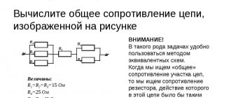
Conductor resistance limits the amount of current in an electrical circuit. The higher the resistance, the lower the current. The conductor resistance can be calculated in two ways: the first method is to use the Ohm's law formula, and the second calculation option involves knowing the geometric dimensions of the conductor and the resistivity of the substance from which it is made.
Content
Different substances have different conductivities. We have already talked about the existence of conductors, semiconductors and dielectrics . Among the conductors of electricity, we have identified metals - they have better conductivity, since they contain a large number of free electrons. These charged particles move under the influence of electric field forces. This is how a phenomenon called electric current arises.
But even among metals, we can distinguish those that conduct current better. This means that there are also metals that conduct current worse. How can we compare this ability of substances? This is how we approach the introduction of a new characteristic of conductors.
This characteristic is called “ electrical resistance ”. In this lesson we will look at its connection with the conductivity of various substances, find out the reasons for its occurrence and understand what other quantities and properties it depends on.
Conductivity and resistivity
Assuming a constant of proportionality σ, the electric field at this location is equal to E
, and the current density is
j
,
J = o E {\displaystyle {\boldsymbol {\mathit {j} }}=\sigma {\boldsymbol {\mathit {E} }}}
Will. σ – material constant, which is called conductivity
(electrical conductivity) or
electrical conductivity
(electrical conductivity).
The inverse of this, 1 ⁄ σ, is called electrical resistivity
(electrical resistivity) or simply
electrical
resistivity (discharge) or electrical
resistivity
(electrical resistivity), and ρ can be used.
Dependence of ammeter and voltmeter readings on the conductor used in the circuit
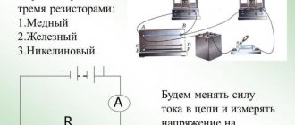
First, let's conduct an interesting experiment. Let's assemble an electrical circuit from a current source, a switch, an ammeter and a voltmeter. We will also include conductors made of various materials in this circuit. They are fixed on a special panel. We will connect a voltmeter in parallel to these same conductors (Figure 1).
Our conductors are designated as follows: AB - iron wire, CD - nickel wire, EF - copper wire.
These conductors have the same length and cross-section.
Figure 1. Dependence of current on the conductor used in the circuit
First we connect the iron wire AB . Let us record the readings of the ammeter and voltmeter after closing the key.
Now let's switch to nickel wire CD . We will notice that the current in the circuit has decreased.
Let's try the third conductor: EF . Now the current has increased significantly .
Have you forgotten that in our experiment there was also a voltmeter? We connected it to each of the conductors in turn.
Each time we got the same voltage value. It didn't change.
Simplified band theory
The bandgap is large for non-conductors.
According to quantum mechanics, electrons in an atom cannot assume any energy value. There are several fixed energy levels that an electron can occupy, and it is impossible to occupy an intermediate state between them. These energy levels are divided into two bands: the "valence band" and the "conduction band", with the latter having higher energy than the former. Electrons in the conduction band can move freely within an object if an electric field is present.
In nonconductors and semiconductors, there is a band gap between the conduction band and the valence band, which is a region of the energy level that electrons cannot occupy. To pass an electric current, a relatively large amount of energy must be supplied to force the electrons to jump across this band gap. Therefore, even if a high voltage is applied, only a relatively small current flows.
Dependence of current on the properties of conductors
You already know that current depends on voltage. After all, voltage is a characteristic of the electric field.
But in our experience the tension remained constant. This means that the current strength has another dependence.
The current strength in the circuit depends on the properties of the conductors included in the electrical circuit.
D.C
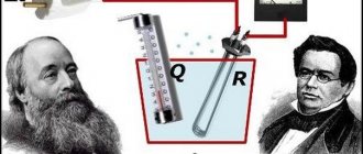
Gentlemen, hello again to everyone! We have already discussed the current. We also discussed tension. The last side of the Bermuda triangle remains. As many have already guessed, today we will talk about electrical resistance . What is it? What does it depend on? How to calculate it? All this will be discussed in today's article!
And it all started quite a long time ago. In the distant and dashing 1800s, the respected Mr. Georg Ohm played in his laboratory with voltage and current, passing it through various things that could conduct it. Being an observant person, he established one interesting relationship. Namely, that if you take the same conductor, then the current strength in it is directly proportional to the applied voltage. Well, that is, if you double the applied voltage, then the current strength will double. Accordingly, no one bothers to take and introduce some proportionality coefficient:
Where G is the coefficient called the conductivity of the conductor. In practice, more often people operate with the reciprocal of conductivity. It is called electrical resistance and is designated by the letter R:
For the case of electrical resistance, the dependence obtained by Georg Ohm looks like this:
Gentlemen, in great confidence, we have just written Ohm’s law. But let's not concentrate on this for now. I almost have a separate article ready for him, and we’ll talk about it in it. Now let us dwell in more detail on the third component of this expression – resistance.
Firstly, this is the characteristics of the conductor. Resistance does not depend on current and voltage, except in certain cases such as nonlinear devices. We will definitely get to them, but later, gentlemen. Now we're looking at regular metals and other nice, simple - linear - things.
Resistance is measured in Ohms . It’s quite logical - whoever discovered it named it after himself. A great incentive for discovery, gentlemen! But remember we started with conductivity? Which is denoted by the letter G? So, it also has its own dimension - Siemens. But usually no one cares about this; almost no one works with them.
An inquisitive mind will certainly ask the question - resistance, of course, is great, but what does it actually depend on? There are answers. Let's go point by point. Experience shows that resistance depends at least on:
- geometric dimensions and shape of the conductor;
- material;
- conductor temperature.
Now let's take a closer look at each point.
Gentlemen, experience shows that at constant temperature the resistance of a conductor is directly proportional to its length and inversely proportional to its cross-sectional area. Well, that is, the thicker and shorter the conductor, the lower its resistance. Conversely, long and thin conductors have relatively high resistance. This is illustrated in Figure 1. This statement is also understandable from the previously cited analogy of electric current and water supply: it is easier for water to flow through a thick short pipe than through a thin and long one, and it is possible to transfer large volumes of liquid in the same time.
Figure 1 – Thick and thin conductors
Let's express this in mathematical formulas:
Here R is the resistance, l is the length of the conductor, S is its cross-sectional area.
When we say that someone is proportional to someone, we can always enter a coefficient and replace the proportionality symbol with an equal sign:
As you can see, here we have a new coefficient. It is called conductor resistivity .
What is it? Gentlemen, it is obvious that this is the resistance value that a conductor 1 meter long and a cross-sectional area of 1 m2 will have. What about its size? Let's express it from the formula:
The value is tabular and depends on the material of the conductor.
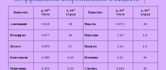
Thus, we smoothly moved on to the second item on our list. Yes, two conductors of the same shape and size, but made of different materials will have different resistance. And this is due solely to the fact that they will have different conductor resistivities. Here is a table with the value of resistivity ρ for some widely used materials.
Gentlemen, we see that silver has the least resistance to electric current, while dielectrics, on the contrary, have a very high resistance. This is understandable. Dielectrics are dielectrics for that reason, so as not to conduct current.
Now, using the plate I provided (or Google, if the required material is not there), you can easily calculate a wire with the required resistance or estimate what resistance your wire will have with a given cross-sectional area and length.
I remember there was one similar case in my engineering practice. We were making a powerful installation to power a laser pump lamp. The power there was simply crazy. And to absorb all this power in case “if something goes wrong”, it was decided to make a 1 Ohm resistor from some reliable wire. Why exactly 1 Ohm and where exactly it was installed, we will not consider now. This is a conversation for a completely different article. It is enough to know that this resistor was supposed to absorb tens of megawatts of power and tens of kilojoules of energy if something happened, and it would be desirable to remain alive. After studying the lists of available materials, I chose two: nichrome and fechral. They were heat-resistant, could withstand high temperatures, and in addition had a relatively high electrical resistivity, which made it possible, on the one hand, to take not very thin (they would immediately burn out) and not very long (you had to fit into reasonable dimensions) wires, and on the other - get the required 1 ohm. As a result of iterative calculations and analysis of market proposals for the Russian wire industry (that’s the term), I finally settled on fechral. It turned out that the wire should have a diameter of several millimeters and a length of several meters. I won’t give exact figures, few of you will be interested in them, and I’m too lazy to look for these calculations in the depths of the archive. The overheating of the wire was also calculated in the event (using thermodynamic formulas) if tens of kilojoules of energy were actually passed through it. It turned out to be a couple of hundred degrees, which suited us.
In conclusion, I will say that these homemade resistors were manufactured and successfully passed tests, which confirms the correctness of the given formula.
However, we were too carried away by lyrical digressions about cases from life, completely forgetting that we also need to consider the dependence of electrical resistance on temperature.
Let's speculate - how can theoretically the resistance of a conductor depend on temperature? What do we know about rising temperatures? At least two facts.
First: with increasing temperature, all atoms of a substance begin to vibrate faster and with greater amplitude. This leads to the fact that the directed flow of charged particles collides more often and more strongly with stationary particles. It’s one thing to get through a crowd of people where everyone is standing, and quite another to get through one where everyone is running around like crazy. Because of this, the average speed of directional movement decreases, which is equivalent to a decrease in current strength. Well, that is, to an increase in the resistance of the conductor to current.
Second: with increasing temperature, the number of free charged particles per unit volume increases. Due to the larger amplitude of thermal vibrations, atoms are more easily ionized. More free particles means more current. That is, the resistance drops.
In total, two processes struggle in substances with increasing temperature: the first and the second. The question is who will win. Practice shows that in metals the first process often wins, and in electrolytes the second process wins. Well, that is, the resistance of a metal increases with increasing temperature. And if you take an electrolyte (for example, water with a solution of copper sulfate), then its resistance decreases with increasing temperature.
There may be cases when the first and second processes completely balance each other and the resistance is practically independent of temperature.
So, resistance tends to change depending on temperature. Let there be resistance R1 at temperature t1. And at temperature t2 it became R2. Then for both the first case and the second, we can write the following expression:
The value α, gentlemen, is called the temperature coefficient of resistance. This coefficient shows the relative change in resistance when the temperature changes by 1 degree. For example, if the resistance of a conductor at 10 degrees is 1000 Ohms, and at 11 degrees – 1001 Ohms, then in this case
The value is tabular. Well, that is, it depends on what kind of material is in front of us. For iron, for example, there will be one value, and for copper - another. It is clear that for the case of metals (resistance increases with increasing temperature) α>0, and for the case of electrolytes (resistance decreases with increasing temperature) α<0.
Gentlemen, for today’s lesson we already have two quantities that affect the resulting resistance of the conductor and at the same time depend on what kind of material it is in front of us. These are ρ, which is the resistivity of the conductor, and α, which is the temperature coefficient of resistance. It is logical to try to bring them together. And so they did! What happened in the end? And here it is:
The value of ρ0 is not entirely unambiguous. This is the conductor resistivity value at Δt=0. And since it is not tied to any specific numbers, but is entirely determined by us – the users – then ρ is also a relative value. It is equal to the value of the resistivity of the conductor at a certain temperature, which we will take as the zero reference point.
Gentlemen, the question arises - where to use this? And, for example, in thermometers. For example, there are such platinum resistance thermometers. The principle of operation is that we measure the resistance of a platinum wire (as we have now found out, it depends on temperature). This wire is a temperature sensor. And based on the measured resistance, we can conclude what the ambient temperature is. These thermometers are good because they allow you to work in a very wide temperature range. Let's say at temperatures of several hundred degrees. Few thermometers will still be able to work there.
And just as an interesting fact - a regular incandescent lamp has a much lower resistance value when switched off than when operating. Let's say, for an ordinary 100-W lamp, the resistance of the filament in a cold state can be approximately 50 - 100 Ohms. Whereas during normal operation it grows to values of the order of 500 Ohms. Resistance increases almost 10 times! But the heating here is around 2000 degrees! By the way, based on the above formulas and measuring the current in the network, you can try to more accurately estimate the temperature of the filament. How? Think for yourself. That is, when you turn on the lamp, a current that is several times higher than the operating current first flows through it, especially if the moment of turning on falls on the peak of the sine wave in the socket. True, the resistance is low for only a short time until the lamp warms up. Then everything returns to normal and the current becomes normal. However, such current surges are one of the reasons why lamps often burn out when they are turned on.
I propose to finish here, gentlemen. The article turned out a little longer than usual. I hope you are not too tired. Great good luck to you all and see you again!
Join our VKontakte group
Questions and suggestions to the admin: This email address is being protected from spambots. You need JavaScript enabled to view it.
Social button for Joomla
Causes of Electrical Resistance
What is the reason for the resistance?
Remember the lesson “Electric current in metals“. Electrons, moving under the influence of an electric field, acquire some direction. But at the same time, the chaotic nature of their movement remains. We also compared this movement to a flock of midges that is carried away by the wind.
So, electrons are brought into ordered motion by an electric field. At the same time, they interact with ions of the crystal lattice. What happens? Orderly movement slows down . Now fewer electrons pass through the cross section of the conductor in $1 \space s$. This means the current decreases.
Let us draw a conclusion from our reasoning.
The reason for resistance is the interaction of moving electrons with ions in the crystal lattice.
It is logical that different conductors will have different resistance values. The whole point will be in the differences in the structure of their crystal lattice. In addition, the length of the conductor and its cross-sectional area will be important. We will talk about this in the following lessons.
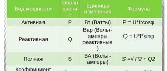
Physical meaning of active resistance (Z)
The concept of a Z circuit is slightly different from the concept of an Ohmic R. In a current circuit, the conversion of electrical energy into mechanical energy can occur. For example, when operating an electric motor or chemical, when charging a battery.
In an AC circuit, electromagnetic energy can be absorbed into the coil core. Energy can be transferred from one circuit to another.
In the case of alternating current, its density in the wires decreases, so the working cross-section of the wire turns out to be less than the geometric size. The actual active R increases compared to the resistance value determined by the specific type. As a result, when using alternating current, the conductor heats up more than when using direct current.
Therefore, in high-frequency radio engineering, conductors are ribbed and the surface is coated with silver or gold, which prevents oxidation.
Active R formula: Z=U*I.
Exercises
Exercise No. 1
Draw a diagram of the circuit shown in Figure 1 and explain the experiment carried out on this drawing.
The electrical circuit diagram is shown in Figure 2. The conductor is indicated by a rectangle.
Figure 2. Electrical circuit diagram for the experiment.
During this experiment, various conductors are used. At the same time, the values of the devices are recorded. The current strength varies depending on which conductor is connected to the circuit. The voltage at the ends of different conductors remains constant all the time.
This experiment proves the connection between current strength and a property of a conductor called electrical resistance.
Exercise No. 2
Express the following resistances in ohms: $100 \space mOhm$;
$0.7 \space kOhm$; $20 \space MOhm$. Given: $I_1 = 100 \space megohm$ $I_2 = 0.7 \space kOhm$ $I_3 = 20 \space megohm$
Show solution and answer
Hide
Solution:
$I_1 = 100 \space mOhm = 100 \cdot 0.001 \space Ohm = 0.1 \space Ohm$, $I_2 = 0.7 \space kOhm = 0.7 \cdot 1000 \space Ohm = 700 \space Ohm$, $I_3 = 20 \space MΩ = 20 \cdot 1 \space 000 \space 000 \space Ohm = 20 \space 000 \space 000 \space Ohm$.
Answer: $I_1 = 0.1 \space Ohm$, $I_2 = 700 \space Ohm$, $I_3 = 20 \space 000 \space 000 \space Ohm$.
Footnotes/Sources
| [How to use footnotes] |
- Electrical conductivity and superconductivity
- Forbes T. Brown (2006). Dynamics of Engineering Systems. CPR Press. p. 43. ISBN 9780849396489. https://books.google.com/books?id=UzqX4j9VZWcC&pg=PA43&dq=%22chordal+resistance%22&as_brr=3&ei=Z0x0Se2yNZHGlQSpjMyvDg
- Kenneth L. Kaiser (2004). Handbook of Electromagnetic Compatibility. CPR Press. pp. 13–52. ISBN 9780849320873. https://books.google.com/books?id=nZzOAsroBIEC&pg=PT1031&dq=%22static+resistance%22+%22dynamic+resistance%22+nonlinear&lr=&as_brr=3&ei=Kk50Ser1MJeOkAS9wNTwDg#PPT1031,M1
- "Scattering due to grating vibration". www.px.tsukuba.ac.jp
. Retrieved June 28, 2022. - Fink and Beaty, Standard Handbook for Electrical Engineers, 11th Edition
, pp. 17-19. - Ward, M.R., Science in Electrical Engineering
, pp. 36–40, McGraw-Hill, 1971. - A. Matthiessen, British Member of the House of Representatives. Ass. 32, 144 (1862)
- A. Matthiessen, Progg. Anallen, 122, 47 (1864)
- Seymour J., Physical Electronics
, Chapter 2, Pitman, 1972
The influence of internal resistance on the properties of a two-terminal network
The higher it is, the less power the source produces when a load is connected. The power in the load can be determined using the formula:
PR = E2/(r+R)2*R,
Where:
- E – EMF voltage;
- R – load resistance;
- r – active internal resistance of a two-terminal network.
The formula is applicable to two-terminal networks that do not release energy.
For your information. When the internal resistance of the two-terminal network approaches the load resistance, the power transfer reaches a maximum.
The total resistance of the circuit when the active and reactive elements are connected in parallel.
In order to calculate the total resistance of a circuit composed of active and inductive resistances connected to each other in parallel (Fig. 5, a), you must first calculate the conductivity of each of the parallel branches, then determine the total conductivity of the entire circuit between points A and B and then calculate the total resistance of the circuit between these points.
Figure 5. Circuit impedance when connecting active and reactive elements in parallel. a) – parallel connection of R and L; b) – parallel connection of R and C.
The conductivity of the active branch, as is known, is equal to 1/R, similarly, the conductivity of the inductive branch is equal to 1/ωL, and the total conductance is equal to 1/Z
Total conductivity is equal to the square root of the sum of the squares of active and reactive conductivity, i.e.
(7)
Reducing the radical expression to a common denominator, we get:
(8)
where:
(9)
Formula (9) is used to calculate the total resistance of the circuit shown in Fig. 5a.
Finding the total resistance for this case can also be done geometrically. To do this, you need to construct a resistance triangle on the appropriate scale, and then divide the product of the lengths of the legs by the length of the hypotenuse. The result obtained will correspond to the total resistance.
Similar to the case discussed above, the total resistance when connecting R and C in parallel will be equal to:
(10)
The total resistance can also be found in this case by constructing a resistance triangle.
In radio engineering, the most common case is the parallel connection of inductance and capacitance, for example, an oscillatory circuit for tuning receivers and transmitters. Since the inductor always has, in addition to inductive resistance, also active resistance, the equivalent (equivalent) circuit of the oscillatory circuit will contain active resistance in the inductive branch (Fig. 7).
Figure 6. Equivalent circuit of an oscillating circuit.
The impedance formula for this case will be:
It will be interesting➡ What types of relay protection exist?
(11)
Since usually the active resistance of the coil (R) is very small compared to its inductive resistance (ωL), we have the right to rewrite formula (11) in the following form:
(12)
In an oscillating circuit, the values of L and C are usually selected so that the inductive reactance is equal to the capacitive reactance, i.e., so that the condition is met
(13)
If this condition is met, the total resistance of the oscillatory circuit will be equal to:
(14)
where L is the inductance of the coil in H;
C is the capacitance of the capacitor in F;
R is the active resistance of the coil in Ohms.