4.2
Average rating: 4.2
Total ratings received: 89.
4.2
Average rating: 4.2
Total ratings received: 89.
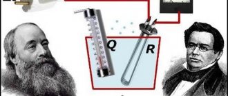
One of the properties of electric current is the heating of the conductors through which it flows. This effect was noticed by many researchers, but its understanding came only after elucidating the mechanism of interaction of charged particles with atoms and molecules of conductors. Heating causes the release of heat and an increase in temperature, and the amount of heat released can be calculated using the Joule-Lenz law formula.
Why do conductors heat up?
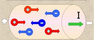
Electric current is the ordered movement of charged particles. In conductors, these particles are negatively charged electrons. The effect of an electric field imparts additional kinetic energy to electrons. As they move, they collide with atoms (or molecules) of the conductor, releasing part of the acquired energy. For this reason, the internal energy of the substance begins to increase, which leads to an increase in temperature and the release of heat.
Rice. 1. Electric current in a conductor heats the conductor
If you take an ordinary incandescent light bulb and connect it to a voltage source through a rheostat (variable resistance), you can observe the thermal effect from the flow of current. By gradually increasing the current, we can first feel by touch that the glass bulb of the light bulb will gradually begin to heat up, and then we will see how the red-hot filament begins to glow.
Note that in this experiment the lead wires do not heat up much and do not glow. This happens because the resistance of the filament is much greater than the resistance of the lead wires.
§ 5.1. Maximum permissible heating temperatures of wires and cables
Electric current causes the wires to heat up. The amount of heat released in this case is proportional to the square of the current, the active resistance of the conductor and the time of current flow: (5.1) where Q is the amount of heat, J; I - current, a; R - active resistance of the wire, ohm: t - time, sec. When heat is released, the temperature of the wire will begin to exceed the ambient temperature. Due to the temperature difference, part of the heat generated in the wire is transferred to the environment. The increase in temperature of the wire will continue until thermal equilibrium occurs, i.e., the moment when the amount of heat that the wire receives per unit time becomes equal to the amount of heat that is given off to the environment in the same period of time. In this case, the temperature of the wire will stop increasing. The temperature at which thermal equilibrium occurs is called steady state. The greater the current, the higher the established temperature. This value of long-term flowing current under constant external conditions (ambient temperature, wind force, precipitation) corresponds to a well-defined steady-state temperature of the wire. In practice, they often use not the value of absolute temperature, but the value of overheating temperature, which is equal to the difference between the temperature of the wire and the environment: (5-2) Excessively high temperature of wires leads to premature drying and aging of the insulation, and for bare wires - to deterioration of contact connections over time. due to intense oxidation (significant increase in transient resistance). In addition, overheating of wires beyond permissible values poses a serious danger (possible fire). PUE establish the following maximum long-term permissible temperatures of wires and cables at which their reliable operation is ensured: For wires with rubber or polyvinyl chloride insulation, cords with rubber insulation and cables in a lead or polyvinyl chloride sheath with rubber insulation ... 65 ° C For cables with paper insulation in lead or aluminum sheath for network voltage: up to 3 kV 80° C up to 6 kV 65° C up to 10 kV 60° C 20 and 35 kV .. 50° C For bare wires .. 70° C
The temperature of the conductor at a given current value does not reach its steady-state value instantly, but after some time after switching on. The law of changes in the temperature values of wire overheating by current can be expressed by the following formula:
t—time, sec; e is the base of natural logarithms (e = 2.71); T is the heating time constant, i.e., the time during which the wire would reach steady-state overheating if there were no heat transfer to the environment (numerically, the time constant is equal to the ratio of the heat capacity of the wire to the heat transfer). When the wire is disconnected from the network, it cools down to ambient temperature. This process can be expressed by equation (5.4) In Fig. 5.1, a and b show the heating and cooling curves of the conductor τ = f(t). The heating time constants depend on the type of wiring, material, cross-section and insulation of the conductor. They are determined experimentally. From expression (5.3) you can easily determine the amount of overheating achieved after a certain time. The given formulas also allow us to solve the problem of how long it will take for the overheating of the conductor to reach a given value.
Under variable load, when it is necessary to determine the overheating temperature starting from a certain value τ, you can use an artificial technique in which the heating process is considered as the sum of two processes:
Pros and cons of electric heating
- Pros . Heating of conductors with electric current finds its application in various useful appliances and devices: electric stoves, kettles, coffee makers, boilers, hair dryers, irons, heaters.
- Minuses . Very often, electronics engineers have to deal with this effect in order, for example, to ensure the functionality of electronic boards, which are stuffed with a huge number of electronic parts, microcircuits, etc. All these elements heat up in accordance with the Joule-Lenz law. And if measures are not taken for forced cooling using metal radiators or fans (coolers), then the boards will quickly fail from overheating.
Rice.
2. Household heating appliances: kettle, iron, hair dryer, electric stove. Often, to quickly connect wires, many people use the “twisting” method. This leads to a significant increase in resistance, and therefore, the “twisted” area will heat up more than the rest of the wiring. Therefore, twisting of wires often causes fires in houses and apartments. To improve contact, you need to solder this place well.
Practical experiences
In order to check how the temperature of the conductor will change depending on fluctuations in the current and resistance parameters, you can conduct some experiments. They are of the following nature:
- A circuit is assembled that includes a power source and 2 heaters with different resistances. When electricity passes through, a heater with greater resistance heats up more. This proves that heating depends on the magnitude of resistance.
- In addition to the power source, a light bulb, an ammeter and a rheostat are connected to the electrical circuit. The voltage is applied and the light comes on. By adjusting the resistance with a rheostat at a constant voltage, the filament will change its brightness. This indicates the dependence of the temperature of the conductor on the current strength.
Such physical experiments must be carried out in special laboratories.
The simplest electrical calculations of heating elements
Electric heaters are widely used in household electrical appliances: kettles, irons, fireplaces, stoves, soldering irons, etc. Thermal effect of current. When an electric current passes through stationary metal conductors, the only result of the work done by the current is the heating of these conductors, and, therefore, according to the law of conservation of energy, all the work done by the current is converted into heat.
The work (in joules) performed by the current as it passes through a section of the circuit is calculated by the formula:
Where:
- U—voltage, V;
- I—current strength, A;
- t- time, s.
The amount of heat (J) released in a conductor when an electric current passes through it is proportional to the square of the current, the resistance of the conductor and the time of passage of the current and is calculated according to the Joule-Lenz law:
where R is the conductor resistance, Ohm.
Let's calculate the amount of heat required to boil water in a kettle holding 2 liters. Mains voltage U=220 V. Current consumed by the electric kettle, I= 4 A. Determine the boiling time of water in the kettle if its efficiency is 80% and the initial water temperature is 20° C.
Initial data:
- U=220 V;
- I=4 A;
- m=2 kg;
- Efficiency=0.8;
- t=20°C;
- tboil = 100° C.
- Specific heat capacity of water C=4200.
Let us determine the amount of heat required to heat water to boiling point.
Qpol = cm (tboil - t0) = 4200 * 2(100 - 20) = 672,000 J.
Let's determine the total amount of heat that the heating element of the electric kettle should release, taking into account the heating losses of the ceramics, the kettle body and the external environment:
Let's determine the boiling time of water in the kettle:
From here we find t;
Electric current power. Knowing the work done by the current over a certain period of time, it is possible to calculate the current power, which, as in mechanics, is understood as the work done per unit of time. From the formula defining the work of direct current A = U//t, it follows that its power (P) is equal to:
They often talk about the power of electric current consumed from the network, wanting to express the idea that with the help of electric current (due to the current), irons, electric stoves, etc. are heated.
In accordance with this, devices are often marked with their power, that is, the current power required for the normal operation of these devices. So, for example, for normal operation of a 220 V electric stove with a power of 500 W, a current of about 2.3 A is required at a voltage of 220 V (2.3 * 220 = 500).
In practice, larger units of power are used: 1 GW (hectowatt) = 100 W and 1 kW (kilowatt) = 1000 W.
Thus, 1 W is the power generated by a current of 1 A in a conductor between the ends of which a voltage of 1 V is maintained.
The unit of work done by an electric current for 1 second using 1 W is called a watt-second, or otherwise a joule. Larger units of work are also used: 1 hectowatt-hour (gW*h) or 1 kilowatt-hour (kW*h), which is equal to the work done by electric current for 1 hour at a power of 1 kW.
The length and diameter of the heating element wire are calculated based on the network voltage and the specified power of the heating element. The current strength at a given voltage and power is determined by the formula:
The ohmic resistance of a conductor is always calculated using the formula:
Knowing the magnitude of the current, you can find the diameter and cross-section of the wire.
Basic data for calculating heating elements:
| Permissible current strength, A | 1 | 2 | 3 | 4 | 5 | 6 | 7 |
| Diameter of nichrome wire at a temperature of 700° C, mm | 0,17 | 0,3 | 0,45 | 0,55 | 0,65 | 0,75 | 0,85 |
| Wire cross-sectional area, mm2 | 0,0227 | 0,0707 | 0,159 | 0,238 | 0,332 | 0,442 | 0,57 |
Substituting the resulting values into the formula:
where: l — wire length, m; S—wire cross-section, mm^2; R—wire resistance, Ohm; p-specific resistance of the wire (for nichrome p = 1.1, for fechral p = 1.3), Ohm*mm^2/m, we obtain the required wire length for the heating element.
Example. Determine the length of the nichrome wire for a tile heating element with a power of P = 600 W at a network voltage of U = 220 V.
From these data we find the diameter and cross-section of the wire: d = 0.45 mm, S = 0.159 mm^2. Then the length of the wire will be equal to:
The heating elements for other electric heating devices can be calculated in the same way.
Note. When operating electrical and radio equipment, it is necessary to know the cross-section of the installation wires, depending on the amount of current passing through them. The table shows the maximum permissible load currents for copper wires of various cross-sections.
Permissible load currents of copper wires (installation):
| Parameter | Wire cross-section, mm^2 | ||||||||||||||
| 0,05 | 0,07 | 0,1 | 0,2 | 0,3 | 0,4 | 0,5 | 0,7 | 1 | 1 ,5 | 2 | 2,5 | 4 | 6 | 10 | |
| Maximum permissible current, A | 0,7 | 1 | 1,3 | 2,5 | 3,5 | 4 | 5 | 7 | 10 | 14 | 17 | 20 | 25 | 30 | 54 |
Literature: V. G. Bastanov. 300 practical tips, 1986